CN202266361U - Long tail water tube for tail water power generation - Google Patents

Long tail water tube for tail water power generation Download PDF

Info

Publication number
CN202266361U
CN202266361U CN2011203407844U CN201120340784U CN202266361U CN 202266361 U CN202266361 U CN 202266361U CN 2011203407844 U CN2011203407844 U CN 2011203407844U CN 201120340784 U CN201120340784 U CN 201120340784U CN 202266361 U CN202266361 U CN 202266361U
Authority
CN
China
Prior art keywords
tail water
long
tube
extension tube
charge
Prior art date
Legal status (The legal status is an assumption and is not a legal conclusion. Google has not performed a legal analysis and makes no representation as to the accuracy of the status listed.)
Expired - Fee Related
Application number
CN2011203407844U
Other languages
Chinese (zh)
Inventor
张增维
林强
梁永丽
Current Assignee (The listed assignees may be inaccurate. Google has not performed a legal analysis and makes no representation or warranty as to the accuracy of the list.)
Chongqing Xin'an Electrical Equipment Co., Ltd. group velocity
Original Assignee
CHONGQING XINAN HYDROPOWER EQUIPMENT MANUFACTURING CO LTD
Priority date (The priority date is an assumption and is not a legal conclusion. Google has not performed a legal analysis and makes no representation as to the accuracy of the date listed.)
Filing date
Publication date
Application filed by CHONGQING XINAN HYDROPOWER EQUIPMENT MANUFACTURING CO LTD filed Critical CHONGQING XINAN HYDROPOWER EQUIPMENT MANUFACTURING CO LTD
Priority to CN2011203407844U priority Critical patent/CN202266361U/en
Application granted granted Critical
Publication of CN202266361U publication Critical patent/CN202266361U/en
Anticipated expiration legal-status Critical
Expired - Fee Related legal-status Critical Current

Links

Images

Classifications

    • YGENERAL TAGGING OF NEW TECHNOLOGICAL DEVELOPMENTS; GENERAL TAGGING OF CROSS-SECTIONAL TECHNOLOGIES SPANNING OVER SEVERAL SECTIONS OF THE IPC; TECHNICAL SUBJECTS COVERED BY FORMER USPC CROSS-REFERENCE ART COLLECTIONS [XRACs] AND DIGESTS
    • Y02TECHNOLOGIES OR APPLICATIONS FOR MITIGATION OR ADAPTATION AGAINST CLIMATE CHANGE
    • Y02EREDUCTION OF GREENHOUSE GAS [GHG] EMISSIONS, RELATED TO ENERGY GENERATION, TRANSMISSION OR DISTRIBUTION
    • Y02E10/00Energy generation through renewable energy sources
    • Y02E10/20Hydro energy

Abstract

The utility model discloses a long tail water tube for tail water power generation. The long tail water tube comprises a taper tube, an elbow tube and a long extending tube, and is characterized in that an upward water catchment well is arranged on the tail part of the long extending tube. The long tail water tube has the advantages that the structure with the water catchment well and the long extending tube is improved, so that the long extending tube can be kept to have water in the dry season, and the small-diameter end of the long extending tube can be filled with water all the time; the taper tube and the elbow tube are ensured to from entering air, so that gas etching phenomenon is avoided, and the service life of the taper tube and the elbow tube is ensured.

Description

Tail water generating long-tail water pipe
Technical field
The utility model relates to the treatment device of tail water after a kind of hydroelectric power, is exactly a kind of tail water generating long-tail water pipe concretely.
Background technique
Existing water turbine generation technology is the strong support of tail water power station design.Conventional hydroelectric power plant all is to build according to the riverbed, and tail water directly enters the tail water downstream, and draft tube is shorter.Power station in underground power house, though draft tube is longer, but its water outlet still directly drains into the rivers bank, and water (flow) direction is a level.But so just exist a kind of bad consequence, in the dry season, probably cause draft tube to surface, when draft tube did not have draining, the draft tube the inside was empty, caused that air gets into draft tube so that arrives ell and Taper Pipe.Thereby the generation cavitation phenomenon, because ell and Taper Pipe are metallic material, so ell and Taper Pipe can produce corrosion, reduces its working life.Therefore be necessary this structure is improved, make ell and Taper Pipe inside advance not air.
The model utility content
The purpose of the utility model just provides a kind of tail water generating long-tail water pipe, solves ell and Taper Pipe and causes cavitation phenomenon and it is carried out the problem of corrosion in the dry season.
The draft tube generating long-tail water pipe of the utility model comprises Taper Pipe, ell and long extension tube, and it is characterized in that: said long extension tube afterbody is provided with outlet charge for remittance well upwards.The purpose that the charge for remittance well is set lets the charge for remittance well also can fill water in the dry season; Because the charge for remittance well is the well shape, opening up, even in the dry season; Do not have on every side under the situation of water; Can store a part of water in the charge for remittance well, can seal, not allow air to get in the draft tube long extension tube.
Further: said long extension tube links to each other the end diameter less than the end that links to each other with the charge for remittance well with ell.Even the use of doing like this is exactly the water of charge for remittance well part evaporation or loss are arranged, because the water table ratio heavy caliber water level at small-bore place is low, equally also can seal long extension tube and ell joint, air can not get into.
Further, said charge for remittance shaft bottom end is mutually neat with the lower end of long extension tube maximum diameter end, and the long extension tube maximum diameter of charge for remittance well aspect ratio end is high.Same reason, such purpose charge for remittance well can all be sealed draft tube, does not allow air to get into draft tube.
Further, the diameter at the long extension tube place that links to each other with ell extends diameter toward charge for remittance well direction and increases gradually, is no longer increasing near back, long extension tube middle part diameter, and equal diameter extends to the charge for remittance well.Its beneficial effect can better let water be full of at the minor diameter place exactly, better seals.
Further, the length of said long extension tube be the Taper Pipe top end diameter 9-15 doubly.Fully guarantee the length of long extension tube, be convenient to be provided with reducer.
The beneficial effect of the utility model is: the structure that charge for remittance well and long extension tube are set is improved; Make long extension tube also can maintain water in the dry season; And make long extension tube smaller diameter end be full of water all the time always; Can guarantee that Taper Pipe and ell have advanced not air, avoid cavitation phenomenon, guarantee the working life of Taper Pipe and ell.
Description of drawings
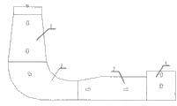
Accompanying drawing is the structural representation of the utility model
Embodiment
Shown in accompanying drawing; The tail water generating draft tube of the utility model comprises Taper Pipe 1 that is arranged on the upper end and the ell 2 that is connected Taper Pipe 1 lower end (Taper Pipe 1 all is that metallic material is processed with ell 2); Said Taper Pipe 1 and ell 2 are through being welded together, and ell 2 is embedded in the concrete fully.Said ell 2 horizontal ends link to each other with long extension tube 3, and long extension tube 3 horizontal arrangement are provided with a charge for remittance well 4 (long extension tube and charge for remittance well are reinforced concrete constructions) at the end of long extension tube 3 in the riverbed.The charge for remittance well communicates with long extension tube; Said Taper Pipe, ell, long extension tube and charge for remittance well all communicate.Water up to standard after the processing drains into the middle of the river through charge for remittance well 4 at last through Taper Pipe 1, ell 2, long extension tube 3.The section configuration of long extension tube is to draw through the analysis of fluid engineering simulation calculation, plays the effect of eliminating negative water hammer.The effect of charge for remittance well 4 is to prevent when dry season, and the river water level is lower than long extension tube 3 upper walls, makes air get into Taper Pipe 1 and produces cavitation phenomenon with ell 2.Current get into from Taper Pipe 1, direction straight down, get into ell 2 after; Water (flow) direction becomes substantially horizontal, gets into charge for remittance well 4 through long extension tube 3 again, flows out from the charge for remittance uphole again; When current flow out the draft tube passage at last; Water flow mode is straight up, has guaranteed it whenever all is water-filled in the whole draft tube like this, does not have air and gets into.The height of charge for remittance well is higher than the maximum diameter place of long extension tube, and the lower end of the maximum diameter end of long extension tube is in the bottom of charge for remittance well.Long extension tube is a reducer, and the end that is connected with ell increases along charge for remittance well direction for minor diameter then gradually, and equal diameter is extended big charge for remittance Jing Chu again.Fully guarantee in long extension tube of dry season, to be full of water, reduced cavitation phenomenon, guaranteed the physical life of Taper Pipe and ell.
As shown in the figure, the Taper Pipe top end diameter is D1, and the length of long extension tube is about 9-15 times of Taper Pipe diameter D1, and the purpose of so doing is exactly to be convenient to have enough length to reach the function of long extension tube.The arrow direction is the flow direction of water among the figure.
Realize the above sewage treatment works of daily handling ability 40 ten thousand steres of the utility model, the electric weight that sends can better be realized energy-saving and emission-reduction, low-carbon economy, the purpose that reduces cost like this in order to the electricity needs of supply sewage treatment works self.

Claims (5)

1. a tail water generating long-tail water pipe comprises Taper Pipe, ell and long extension tube, and it is characterized in that: said long extension tube afterbody is provided with the charge for remittance well.
2. tail water generating long-tail water pipe according to claim 1, it is characterized in that: said long extension tube links to each other the end diameter less than the end that links to each other with the charge for remittance well with ell.
3. tail water generating long-tail water pipe according to claim 1 and 2, it is characterized in that: said charge for remittance shaft bottom end is mutually neat with the lower end of long extension tube maximum diameter end, and the long extension tube maximum diameter of charge for remittance well aspect ratio end is high.
4. tail water generating long-tail water pipe according to claim 1; It is characterized in that: the diameter at the long extension tube place that links to each other with ell extends diameter toward charge for remittance well direction and increases gradually; No longer increasing near back, long extension tube middle part diameter, equal diameter extends to the charge for remittance well.
5. according to claim 1,2 or 4 described tail water generating long-tail water pipes, it is characterized in that: the length of said long extension tube is 9-15 times of Taper Pipe top end diameter.
CN2011203407844U 2011-08-31 2011-08-31 Long tail water tube for tail water power generation Expired - Fee Related CN202266361U (en)

Priority Applications (1)

Application Number Priority Date Filing Date Title
CN2011203407844U CN202266361U (en) 2011-08-31 2011-08-31 Long tail water tube for tail water power generation

Applications Claiming Priority (1)

Application Number Priority Date Filing Date Title
CN2011203407844U CN202266361U (en) 2011-08-31 2011-08-31 Long tail water tube for tail water power generation

Publications (1)

Publication Number Publication Date
CN202266361U true CN202266361U (en) 2012-06-06

Family

ID=46157159

Family Applications (1)

Application Number Title Priority Date Filing Date
CN2011203407844U Expired - Fee Related CN202266361U (en) 2011-08-31 2011-08-31 Long tail water tube for tail water power generation

Country Status (1)

Country Link
CN (1) CN202266361U (en)

Cited By (4)

* Cited by examiner, † Cited by third party
Publication number Priority date Publication date Assignee Title
CN103670877A (en) * 2013-11-21 2014-03-26 南通高盛机械制造有限公司 Improved exhaust water pipe
CN103670882A (en) * 2013-11-21 2014-03-26 南通高盛机械制造有限公司 Tail water pipe
CN105257454A (en) * 2015-10-12 2016-01-20 武汉大学 Diversion type vortex flow power generation system
CN109477328A (en) * 2016-07-07 2019-03-15 尼尔森灌溉公司 The centrally-pivoted axle of modified cross-sectional diameter irrigates gooseneck

Cited By (6)

* Cited by examiner, † Cited by third party
Publication number Priority date Publication date Assignee Title
CN103670877A (en) * 2013-11-21 2014-03-26 南通高盛机械制造有限公司 Improved exhaust water pipe
CN103670882A (en) * 2013-11-21 2014-03-26 南通高盛机械制造有限公司 Tail water pipe
CN105257454A (en) * 2015-10-12 2016-01-20 武汉大学 Diversion type vortex flow power generation system
CN109477328A (en) * 2016-07-07 2019-03-15 尼尔森灌溉公司 The centrally-pivoted axle of modified cross-sectional diameter irrigates gooseneck
CN109477328B (en) * 2016-07-07 2021-05-28 尼尔森灌溉公司 Center pivot irrigation gooseneck with varying cross-sectional diameter
US11085568B2 (en) 2016-07-07 2021-08-10 Nelson Irrigation Corporation Center pivot irrigation gooseneck with varying cross-sectional diameters

Similar Documents

Publication Publication Date Title
CN103216375B (en) A kind of bulb through-flow turbine for micro-water head power station
CN201110242Y (en) Siphoning type pipe generator
CN103352452B (en) Flexible double-tube water diversion, electricity generation and water storage integrated device suitable for rivulets in mountainous areas
CN206752426U (en) A kind of Novel flush storage station water system
CN202266361U (en) Long tail water tube for tail water power generation
CN104696175A (en) Low water head energy collecting device and method
CN206607576U (en) A kind of full-automatic well-point back pumping system
CN209067405U (en) Siphon type electricity generating
CN203383196U (en) Flexible double-pipeline water diversion power generation water storage integrated equipment applicable to mountain stream
CN201739070U (en) Water flow generating set
CN101900137A (en) Method for pumping by using siphon principle
CN103867377A (en) System device for generating power through water wave force
CN204145366U (en) A kind of grid-connected power generation system
CN203808031U (en) Sealed type hydropower station pressure regulating chamber
CN106381903A (en) Automatic flow diverging system for groundwater recharging of well groups
CN105736219A (en) Siphonic power generation system
CN201412262Y (en) Pipeline cascaded power generating system
CN205503341U (en) Current power generation gathers a class cover with adjustable
CN201614576U (en) Natural water drawing device for pipe bundle electricity generation
CN107939592A (en) New energy hydroelectric generation tower
CN201766455U (en) Compressed air power generating device powered by rotation of large rotary wheel
CN201778944U (en) Graded cascading hydro-power generating unit
CN204511793U (en) A kind of low water head energy collecting device
CN103161655B (en) Buoyancy aid lifting power electricity generating device
CN102536604A (en) Hydropower generation method using shallow and narrow riverbed

Legal Events

Date Code Title Description
C14 Grant of patent or utility model
GR01 Patent grant
C41 Transfer of patent application or patent right or utility model
TR01 Transfer of patent right

Effective date of registration: 20160329

Address after: 401147, 62 North Star Road, New District, Chongqing (6 floors, 4 floor, Neptune science building, B District)

Patentee after: Chongqing Xin'an Electrical Equipment Co., Ltd. group velocity

Address before: 401336 No. 5 Camellia Road, tea garden, Nan'an District, Chongqing

Patentee before: Chongqing Xinan Hydropower Equipment Manufacturing Co.,Ltd.

CF01 Termination of patent right due to non-payment of annual fee

Granted publication date: 20120606

Termination date: 20170831

CF01 Termination of patent right due to non-payment of annual fee