CN202194600U - Constant pressure degasser - Google Patents
Constant pressure degasser Download PDFInfo
- Publication number
- CN202194600U CN202194600U CN 201120321278 CN201120321278U CN202194600U CN 202194600 U CN202194600 U CN 202194600U CN 201120321278 CN201120321278 CN 201120321278 CN 201120321278 U CN201120321278 U CN 201120321278U CN 202194600 U CN202194600 U CN 202194600U
- Authority
- CN
- China
- Prior art keywords
- storehouse
- bin
- exhaust
- gas
- atm
- Prior art date
- Legal status (The legal status is an assumption and is not a legal conclusion. Google has not performed a legal analysis and makes no representation as to the accuracy of the status listed.)
- Expired - Fee Related
Links
Images


Landscapes
- Degasification And Air Bubble Elimination (AREA)
Abstract
The utility model provides a constant pressure degasser, in particular to a drilling fluid processing device for oil drilling, which comprises a cylindrical gas-liquid separating bin with the front end capable of penetrating into mud. The tail end of the gas-liquid separating bin is fixed and communicated with a liquid discharging bin, the gas-liquid separating bin and the liquid discharging bin are supported by a protective frame and fixed relative to the protective frame, and a liquid discharging port is arranged on the bin wall of the liquid draining bin. An inner cavity of the liquid draining bin is provided with a venting bin fixed with the bin wall of the liquid draining bin and defined by the liquid draining bin, and the tail end face of the venting bin supports a speed reducer casing. The tail end of the venting bin is airtight, the front end of the venting bin is in a semi-open structure for air to enter freely and capable of preventing the mud from entering, and the venting bin is communicated with a venting device. An output shaft of a speed reducer is connected with a spindle impeller assembly which is arranged in the gas-liquid separating bin and coaxial with the gas-liquid separating bin. The constant pressure degasser adopts the spindle impeller assembly to stir the mud and enable the mud to rise in a rotating mode, air in the mud overflows under the action of centrifugal force, rotation of an impeller serves as a power source and an energy source for degassing, thereby saving energy consumption and being high in degassing efficiency.
Description
Technical field
The utility model provides a kind of atm-degasser, and a kind of drilling fluid treatment facility especially for oil drilling belongs to oil drilling equipment technology field.
Background technology
At present, domestic petroleum drilling well industry deaerator can be divided into two kinds of vacuum type deaerator and gerotor type deaerators by its operating principle:
1. vacuum type deaerator basic functional principle is by air in the vacuum pump aspirated liquid gas separation bin, forms negative pressure, and gas cut mud is pressed in the liquid gas separation bin by atmospheric pressure, and by the stand straticulation, the interior gas of mud overflows under negative pressure state and collected by vacuum pump.The vacuum type deaerator is bulky usually, and it is bigger to take jar space of planes, and structure is comparatively complicated.
2. gerotor type deaerator basic functional principle is impeller rotation on the driven by motor reducer driving main shaft; Impeller drives gas cut mud; Rotate rising along cylinder inner wall, mud receives the impeller stirring to be close to the concentrator bowl inwall by the stand straticulation, and the interior gas of mud receives centrifugal action and overflows; Collected the back by blower fan and discharge, the mud of degasification continuation rising is discharged by leakage fluid dram.Gerotor type deaerator structure is simpler, light than vacuum type deaerator, be easy to install, Operation and maintenance.When handling low-gravity, low viscous mud, effect is more remarkable.
The utility model content
The utility model technical issues that need to address provide a kind of atm-degasser that all can steady operation under various mud balances, various viscosity and various drilling well situation.
For solving the problems of the technologies described above, the technical scheme that the utility model adopted is:
Comprise that its front end can probe into the cylindric gas-liquid separation storehouse of mud, gas-liquid separation storehouse tail end is fixed and is communicated with the discharge opeing storehouse, and gas-liquid separation storehouse and discharge opeing storehouse are supported by fender bracket and relative fender bracket is fixed, and the bulkhead in discharge opeing storehouse is offered leakage fluid dram; The bulkhead in inner chamber setting of discharge opeing storehouse and discharge opeing storehouse is fixed and by the exhaust storehouse of discharge opeing storehouse encirclement, exhaust storehouse breech face supports the reducer casing; Exhaust storehouse tail end is airtight, front end for can free air inlet, can prevent the semi-open structure that mud gets into simultaneously, the exhaust storehouse is communicated with exhaust plant; The reducer output shaft connection is arranged in the gas-liquid separation storehouse and the main shaft impeller assembly coaxial with the gas-liquid separation storehouse.
The further improvement of the utility model is:
Said exhaust storehouse front end is provided with liquid gas separating mechanism mechanism: the fixing back-up ring of housing front end that comprises the exhaust storehouse; The circular slip ring that back-up ring outer face outstanding is coaxial with the main shaft of atm-degasser; The back-up ring outer end is provided with and can be connected with the main shaft with the normal pressure deaerator and with the liquid gas separator disk of main axis rotation, the inner face of liquid gas separator disk is provided with catch, and chute is offered in the outer face of catch; Chute and said slip ring interlock are deposited the gap between chute and the slip ring.
Gap between said chute and the slip ring is an adjustable clearance.
Said fender bracket comprises and can the main motor and the reducer of atm-degasser be surrounded, and supports the bracing frame of atm-degasser main body.
Support frame as described above is a frame construction, bracing frame top welding hanging ring, welding full blast blast fan fixed head on the bracing frame, welding electric control box fixed head on the bracing frame, welding exhaust line support on the bracing frame.
Said exhaust plant comprises the air inlet pipe that is communicated with the exhaust storehouse, and air inlet pipe is communicated with exhaust opening through connecting line, and exhaust opening connects the explosion-proof blast fan of full blast that can make connecting line and air inlet pipe inner chamber form negative pressure.
Said connecting line is extended upward by the height and position of air inlet pipe and is communicated with exhaust opening, and the connecting line bottom is provided with manual pressure regulating valve, and the meta of connecting line is provided with automatic pressure regulator.
Because the technological progress of having adopted technique scheme, the utility model to obtain is:
The cylindric gas-liquid separation storehouse of the utility model directly probes into mud, adopts the main shaft impeller assembly to stir mud, and the mud rotation is risen; Gas in the mud overflows under action of centrifugal force; The rotation of impeller is again the energy source of degasification both as power source, has saved energy consumption; This kind of atm-degasser treating capacity is 300m3/h, greater than the treating capacity of general deaerator 240 m3/h; Through calculating, this kind of atm-degasser is 2.5 times of general vacuum degasser degassing efficiency.
The exhaust storehouse that its exhaust plant is installed in atm-degasser connects, and through full blast blast fan suction air, forms lower negative pressure, collects the gas that discharges in the mud; Can satisfy the instructions for use of atm-degasser, and compact conformation, outward appearance is novel; The standard component utilization rate is high, and maintenance is convenient, and is simple to operate; Manual pressure regulating valve, automatic pressure regulator guarantee that bricklayer's delivered pressure is stable, slurries face position is normal, can adapt to the mud of various proportions and viscosity, and the upwardly extending structure design of connecting line can prevent that mud from overflowing from the full blast blast fan; Manual pressure regulating valve also can be used as the clear water import, and after atm-degasser used, the flushing atm-degasser was inner.
Its liquid gas separating mechanism can stop effectively that mud gets into the exhaust storehouse, the protection gas exhaust piping, and its catch can throw away the liquid that flows to above it; Thereby stop liquid to get into the exhaust storehouse, and gas does not receive the influence of this device, directly gets into the exhaust storehouse; Realize the discharge opeing storehouse of atm-degasser and the gas-liquid separation between the exhaust storehouse; The atm-degasser stability and high efficiency requirements of one's work that satisfy, liquid gas separator disk and back-up ring are used, and the adjustable gaps joint between the two is with the size of air inlet port.
Its fender bracket is when realizing that atm-degasser supports, and to the motor of atm-degasser, reducer and control device play effective protective effect, also can conveniently lift, transport, compact conformation.
The utility model can satisfy the degasification of various mud balances, various viscosity mud, and low consumption, high throughput, degassing effect are good.
Simple in structure, the more reliable performance of the utility model, simple to operate, degassing efficiency is high, can be good at adapting to complicated drillng operation condition.
Description of drawings
Fig. 1 is a kind of structural representation of atm-degasser;
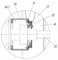
Fig. 2 is the A enlarged drawing of Fig. 1;
Fig. 3 is the structural representation of Fig. 2 guide ring;
Fig. 4 is that figure is watched in the structural representation of liquid gas separator disk among Fig. 2 attentively;
Fig. 5 is the A-A sectional view of Fig. 4.
Fig. 6 is the structural representation of fender bracket among Fig. 1;
Fig. 7 is the vertical view of Fig. 6;
Fig. 8 is the structural representation of exhaust plant among Fig. 1;
Fig. 9 is the left view of Fig. 8.
Wherein: 1, motor, 2, reducer, 4, exhaust plant, 5, fender bracket, 6, the main shaft impeller assembly, 7, the discharge opeing storehouse, 8, the gas-liquid separation storehouse, 9, leakage fluid dram,
41, manual pressure regulating valve, 42, automatic pressure regulator, 43, the full blast blast fan, 44, connecting line, 45, air inlet pipe, 46, exhaust opening,
51, suspension ring, 52, full blast blast fan fixed head, 53, the electric control box fixed head, 54, the exhaust line support, 55, bracing frame,
A1, back-up ring, A1-1, slip ring, A2, liquid gas separator disk, A3, catch, A3-1, chute, A4, housing, A4-1, exhaust storehouse, A5, main shaft, A6, discharge opeing storehouse.
The specific embodiment
Below in conjunction with accompanying drawing the utility model is explained further details:
Shown in Figure 1; The utility model comprises that front end can probe into the cylindric gas-liquid separation storehouse 8 of mud; Gas-liquid separation storehouse 8 tail ends are fixed and are communicated with discharge opeing storehouse 7, and gas-liquid separation storehouse 8 and discharge opeing storehouse 7 are supported by fender bracket 5 and fender bracket 5 is fixing relatively, and the bulkhead in discharge opeing storehouse 7 is offered leakage fluid dram 9;
The bulkhead in 7 inner chamber settings of discharge opeing storehouse and discharge opeing storehouse 7 is fixed and by the exhaust storehouse A4-1 of discharge opeing storehouse 7 encirclements, exhaust storehouse A4-1 breech face supports reducer 2 casings;
Exhaust storehouse A4-1 tail end is airtight, front end for can free air inlet, can prevent the semi-open structure that mud gets into simultaneously, exhaust storehouse A4-1 is communicated with exhaust plant 4;
Reducer 2 output shafts connect and to be arranged in the gas-liquid separation storehouse 8 and the main shaft impeller assembly 6 coaxial with gas-liquid separation storehouse 8.
The atm-degasser course of work of the utility model is following:
The gas-liquid separation storehouse 8 of atm-degasser is goed deep in the mud, the rotation of motor 1 drivening piece reducer 2 driving main shaft impeller assemblies 6, gas cut mud risings that be driven to rotate, entering liquid gas separation bin 8; Mud receives centrifugal action, is thrown toward liquid gas separation bin 8 inwalls, is spread out by the high-speed motion impeller; Form wadding stream thin-walled, be the eddy current shape and do the rotation ascending motion, the big mud of density is near liquid gas separation bin 8 inwalls; The bubble that density is little moves to the inside, arrives the liquid skin breakage, and gas overflows; Mud continues to rise and arrives discharge opeing storehouse 7, discharges from the leakage fluid dram 9 in discharge opeing storehouse 7; After gas overflows, the suction function that formed by full blast blast fan 43, gas is collected, is discharged through part exhaust plant 4 by exhaust storehouse A4-1.
Fig. 2,3, shown in 4 or 5, said exhaust storehouse A4-1 front end is provided with liquid gas separating mechanism mechanism:
Be included in the fixing back-up ring A1 of housing A4 front end of exhaust storehouse A4-1; The circular slip ring A1-1 that the principal axis A 5 of back-up ring A1 outer face outstanding one and atm-degasser is coaxial; Back-up ring A1 outer end is provided with and can be connected with the principal axis A 5 with the normal pressure deaerator and with the liquid gas separator disk A2 of main axis rotation, the inner face of liquid gas separator disk A2 is provided with catch A3, and chute A3-1 is offered in the outer face of catch A3; Chute A3-1 and said slip ring A1-1 interlock are deposited the gap between chute A3-1 and the slip ring A1-1.Gap between said chute A3-1 and the slip ring A1-1 is an adjustable clearance.
This exhaust gear can stop that mud gets into exhaust storehouse A4-1, the protection gas exhaust piping.When atm-degasser turns round; Liquid gas separator disk A2 and principal axis A 5 are together rotated, and rotation produces centrifugal force, under the drive of the catch A3 of liquid gas separator disk A2; The mud that splashes on the liquid gas separator disk A2 is thrown away separator disk; Fall back to discharge opeing storehouse A6, and gas does not receive the influence of this device, can freely pass through.Liquid gas separator disk A2 and back-up ring A1 are used, and the adjustable gaps joint between the two is with the size of air inlet port.
Fig. 8 or shown in Figure 9, the structure of said exhaust plant 4 comprises:
The air inlet pipe 45 that is communicated with the exhaust storehouse A4-1 of atm-degasser, air inlet pipe is communicated with exhaust opening 46 through connecting line 44, and exhaust opening 46 connects can be with the explosion-proof blast fan 43 of the full blast that gas exhaust piping vacuumizes.
Said connecting line 44 is extended upward by the air inlet pipe height and is communicated with exhaust opening 46.
Connecting line 44 bottoms are provided with manual pressure regulating valve 41.
Connecting line 44 metas are provided with automatic pressure regulator 42.
Guarantee that through regulating automatic pressure regulator 42 the mud liquid level position is normal, operating pressure stable.
When the exhaust plant negative pressure is excessive, regulate manual pressure regulating valve 41, assurance equipment is worked in working pressure range.
Full blast blast fan 43 suction air in the exhaust plant forms 4KPa left and right sides lower negative pressure in device, the gas collection that mud is discharged also is discharged into the safety zone.
When connecting line 44 upwardly extending structure designs can prevent that mud level is too high, overflow mud from the full blast blast fan.
Manual pressure regulating valve 41 also can be used as the clear water import, after atm-degasser uses, and the inner residual slip of flushing atm-degasser, the cleaning of maintenance equipment.
Guarantee that through manual pressure regulating valve 41, automatic pressure regulator 42 the mud liquid level position is normal, operating pressure stable, full blast blast fan 43 suction airs form lower negative pressure, collect the gas that mud discharges, and can adapt to the mud of various proportions and viscosity; Upwardly extending connecting line 44 can prevent that mud level is too high and overflow from full blast blast fan 43; Manual pressure regulating valve 41 also can connect the clear water pipeline, the inner residual slip of flushing atm-degasser, the cleaning of maintenance equipment.
Shown in Fig. 6 or 7, said protection sees that frame 5 structures comprise:
Can the main motor and the reducer of atm-degasser be surrounded and support atm-degasser body supports frame 55.
Bracing frame 55 is a frame construction.
Full blast blast fan fixed head 52 is welded on the bracing frame 55, is used for fixing the full blast blast fan;
Electric control box fixed head 53 is welded on the bracing frame 55, is used for fixing electric control box;
Exhaust line support 54 is welded on the part bracing frame, is used to support exhaust line;
Bracing frame 55 is used to protect each parts and support member suspension ring 51, full blast blast fan fixed head 52, electric control box fixed head 53 and exhaust line support 54.
This fender bracket can satisfy atm-degasser lifting, convenient transportation, and requirements such as compact conformation integrate various functions, both can be used as the effect of transport support, and the function of lifting and protection is arranged again.
The utility model can satisfy the needs that use on-the-spot low consumption, high throughput, deaerator that degassing effect is good.
Adopt main shaft impeller assembly 6 to stir mud, the mud rotation is risen, the gas in the mud overflows under action of centrifugal force, and the rotation of impeller is again the energy source of degasification both as power source, has saved energy consumption; This kind of atm-degasser treating capacity is 300m3/h, greater than the treating capacity of general deaerator 240 m3/h; Through calculating, this kind of atm-degasser is 2.5 times of general vacuum degasser degassing efficiency.
Atm-degasser lifts in order to satisfy, convenient transportation, requirements such as compact conformation, and the utility model has designed a kind of fender bracket that integrates various functions, the effect of existing transport support, the function that lifting is arranged again and protect.
Claims (7)
1. atm-degasser; It is characterized in that: comprise that its front end can probe into the cylindric gas-liquid separation storehouse of mud; Gas-liquid separation storehouse tail end is fixed and is communicated with the discharge opeing storehouse, and gas-liquid separation storehouse and discharge opeing storehouse are supported by fender bracket and relative fender bracket is fixed, and the bulkhead in discharge opeing storehouse is offered leakage fluid dram; The bulkhead in inner chamber setting of discharge opeing storehouse and discharge opeing storehouse is fixed and by the exhaust storehouse of discharge opeing storehouse encirclement, exhaust storehouse breech face supports the reducer casing; Exhaust storehouse tail end is airtight, front end for can free air inlet, can prevent the semi-open structure that mud gets into simultaneously, the exhaust storehouse is communicated with exhaust plant; The reducer output shaft connection is arranged in the gas-liquid separation storehouse and the main shaft impeller assembly coaxial with the gas-liquid separation storehouse.
2. a kind of atm-degasser according to claim 1; It is characterized in that: said exhaust storehouse front end is provided with liquid gas separating mechanism; Liquid gas separating mechanism comprises the back-up ring that the housing front end in exhaust storehouse is fixing, the circular slip ring that back-up ring outer face outstanding is coaxial with the main shaft of atm-degasser, and the setting of back-up ring outer end can be connected with the main shaft with the normal pressure deaerator and with the liquid gas separator disk of main axis rotation; The inner face of liquid gas separator disk is provided with catch; Chute is offered in the outer face of catch, and chute and said slip ring interlock are deposited the gap between chute and the slip ring.
3. a kind of atm-degasser according to claim 2 is characterized in that: the gap between said chute and the slip ring is an adjustable clearance.
4. a kind of atm-degasser according to claim 1 is characterized in that: said fender bracket comprises and can the main motor and the reducer of atm-degasser be surrounded, and supports the bracing frame of atm-degasser main body.
5. according to the said a kind of atm-degasser of claim 4, it is characterized in that: support frame as described above is a frame construction, bracing frame top welding hanging ring, full blast blast fan fixed head, electric control box fixed head and exhaust line support.
6. a kind of atm-degasser according to claim 1; It is characterized in that: said exhaust plant comprises the air inlet pipe that is communicated with the exhaust storehouse; Air inlet pipe is communicated with exhaust opening through connecting line, and exhaust opening connects the explosion-proof blast fan of full blast that can make connecting line and air inlet pipe inner chamber form negative pressure.
7. a kind of atm-degasser according to claim 6 is characterized in that: said connecting line is extended upward by the height and position of air inlet pipe and is communicated with exhaust opening, and the connecting line bottom is provided with manual pressure regulating valve, and the meta of connecting line is provided with automatic pressure regulator.
Priority Applications (1)
| Application Number | Priority Date | Filing Date | Title |
|---|---|---|---|
| CN 201120321278 CN202194600U (en) | 2011-08-30 | 2011-08-30 | Constant pressure degasser |
Applications Claiming Priority (1)
| Application Number | Priority Date | Filing Date | Title |
|---|---|---|---|
| CN 201120321278 CN202194600U (en) | 2011-08-30 | 2011-08-30 | Constant pressure degasser |
Publications (1)
| Publication Number | Publication Date |
|---|---|
| CN202194600U true CN202194600U (en) | 2012-04-18 |
Family
ID=45949517
Family Applications (1)
| Application Number | Title | Priority Date | Filing Date |
|---|---|---|---|
| CN 201120321278 Expired - Fee Related CN202194600U (en) | 2011-08-30 | 2011-08-30 | Constant pressure degasser |
Country Status (1)
| Country | Link |
|---|---|
| CN (1) | CN202194600U (en) |
Cited By (2)
| Publication number | Priority date | Publication date | Assignee | Title |
|---|---|---|---|---|
| CN102337846A (en) * | 2011-08-30 | 2012-02-01 | 中国石油集团渤海石油装备制造有限公司 | Atmospheric pressure degasser |
| CN103480181A (en) * | 2013-09-10 | 2014-01-01 | 国家地质实验测试中心 | Multi-vane anisotropic turbulent flow type low-pressure and self-balancing slurry degassing device |
-
2011
- 2011-08-30 CN CN 201120321278 patent/CN202194600U/en not_active Expired - Fee Related
Cited By (3)
| Publication number | Priority date | Publication date | Assignee | Title |
|---|---|---|---|---|
| CN102337846A (en) * | 2011-08-30 | 2012-02-01 | 中国石油集团渤海石油装备制造有限公司 | Atmospheric pressure degasser |
| CN103480181A (en) * | 2013-09-10 | 2014-01-01 | 国家地质实验测试中心 | Multi-vane anisotropic turbulent flow type low-pressure and self-balancing slurry degassing device |
| CN103480181B (en) * | 2013-09-10 | 2015-04-15 | 国家地质实验测试中心 | Multi-vane anisotropic turbulent flow type low-pressure and self-balancing slurry degassing device |
Similar Documents
| Publication | Publication Date | Title |
|---|---|---|
| JP4621802B1 (en) | Self-priming solid-liquid separator | |
| CN109236677A (en) | A kind of express pump of the preposition taper inducer of band | |
| CN202194600U (en) | Constant pressure degasser | |
| CN208650839U (en) | A kind of oil-gas exploration gas well gas invades the gas-liquid separation device of water burst | |
| CN102337846A (en) | Atmospheric pressure degasser | |
| CN110841377A (en) | Grid type elastic separating device | |
| CN106587257A (en) | Reciprocating type cyclone dirt removal system | |
| CN205032287U (en) | Associated mode oil purification machine | |
| CN107982962B (en) | Fluid online bubble removing device | |
| TWI535480B (en) | Oil sump collection device | |
| CN207056102U (en) | One kind machining waste liquid grease separation and advanced treatment apparatus | |
| CN215592767U (en) | Three-phase rotational flow extraction device | |
| CN108869310A (en) | A kind of gas-liquid separation device on centrifugal pump | |
| JP3154627U (en) | Gas separator | |
| CN211900569U (en) | Liquid drainage and gas production device for natural gas well | |
| CN201644245U (en) | Forced sand-discharging and solid-liquid separating cyclone device | |
| CN211026735U (en) | Explosion-proof device in horizontal spiral continuous filtering centrifuge | |
| CN103787450B (en) | Settling tank jet flow self-spinning and self-absorbing oil receiving device and method | |
| CN207468252U (en) | Spin current flotation device | |
| CN105170345A (en) | Direct connection type oil purifying machine | |
| CN201599993U (en) | Novel centrifugal type oil separator | |
| CN220143691U (en) | Degassing device of vertical centrifugal separator | |
| CN111841085A (en) | Water wheel centrifugal defoaming device | |
| CN202194601U (en) | Venting device of constant pressure degasser | |
| CN212732621U (en) | Cyclone separator with cleaning device |
Legal Events
| Date | Code | Title | Description |
|---|---|---|---|
| C14 | Grant of patent or utility model | ||
| GR01 | Patent grant | ||
| CF01 | Termination of patent right due to non-payment of annual fee |
Granted publication date: 20120418 Termination date: 20190830 |
|
| CF01 | Termination of patent right due to non-payment of annual fee |