CN202168320U - Fin type radiating device - Google Patents
Fin type radiating device Download PDFInfo
- Publication number
- CN202168320U CN202168320U CN2011202875739U CN201120287573U CN202168320U CN 202168320 U CN202168320 U CN 202168320U CN 2011202875739 U CN2011202875739 U CN 2011202875739U CN 201120287573 U CN201120287573 U CN 201120287573U CN 202168320 U CN202168320 U CN 202168320U
- Authority
- CN
- China
- Prior art keywords
- base
- radiating fin
- shackle member
- groove
- finned radiator
- Prior art date
- Legal status (The legal status is an assumption and is not a legal conclusion. Google has not performed a legal analysis and makes no representation as to the accuracy of the status listed.)
- Expired - Fee Related
Links
Images


Abstract
The utility model relates to the technical field of a radiating device, in particular to a fin type radiating device, which comprises a base and a plurality of radiating fins. Root portions of the radiating fins are connected with the base and extend to form a clamping piece. The base is provided with a groove corresponding to the clamping piece which is clamped with the groove, and a plurality of radiating fins are laminated to form a radiating fin group. The radiating fins can be punched into the clamping piece, and the clamping piece can be clamped in the groove through punching, thereby enabling the radiating fins to be connected with the base fast, being big in contact area between the radiating fins and the base and capable of conducting heat fast, and improving heat transfer efficiency.
Description
Technical field
The utility model relates to the heat sink technology field, relates in particular to a kind of finned radiator.
Background technology
Along with the development of technology, the size of electronic product is more and more littler, and correspondingly the caloric value of unit space is increasing, and this has higher requirement to heat radiation, and radiator has become the indispensable accessory of some electronic products.If radiator commonly used is made up of a base and a plurality of fins group with heat transfer thermolysis, fins group comprises the fin of a plurality of stacked arrangement, and radiator can also be provided with heat pipe to strengthen radiating effect.
Whether the contact area size of fin and base, to be connected firmly be the key factor that influences radiator heat-dissipation efficient, and it is a committed step in the radiator production that fin is connected with base.A kind of method commonly used is: with fin and base through being welded to connect; It must be with tin cream or other welding compounds media as welding; According to the material of fin and base, some also need carry out Nickel Plating Treatment, and application number is " 200410003352.9 "; Denomination of invention is the Chinese invention patent application of " welded heat radiator preparation method ", promptly discloses a kind of through being welded to connect the method for fin and base.
Use the method for above-mentioned welding, complex process, cost are higher, and production efficiency is low, and be unfriendly to environment, and therefore another kind of method commonly used is: improve the structure of base, fin, with fin through being embedded or the mode of mechanical connection such as riveted joint connects base.For example: the patent No. is " 03279661.7 "; Patent name is the Chinese utility model patent of " heat radiation seat structure "; And the patent No. is " 200620063119.4 "; Patent name is the Chinese utility model patent of " radiator fins and base combined improved ", and the method that two patents are used is specially: the fin that each is independent is inserted preset fluted base piecewise, thereby uses the mould extruded channels to make the groove distortion; Make the sheet root of fin form interference fit, thereby make fin be fixedly connected base with the groove after the distortion.It is cumbersome that this process is not only processed groove; And because the gap between fin is very little; Make the mould extruded channels working procedure processing inconvenience, consuming time long, defect rate is high, though therefore the above-mentioned relatively radiator that is welded of this method has certain advantage, has still that operation is more, an inconvenient machining, the higher shortcoming of cost; And the sheet root of fin and the contact area of base are limited, influence radiating efficiency.
Summary of the invention
The purpose of the utility model is exactly to the deficiency of prior art existence a kind of finned radiator to be provided, and its radiating fin can be connected with base fast, and both contacts area are big, and heat transfer efficiency is high.
To achieve these goals; The technical scheme that the utility model adopts is: a kind of finned radiator, comprise base, a plurality of radiating fin, and said radiating fin root connects said base; Said radiating fin root is extended with shackle member; Said base is provided with and said shackle member corresponding groove, said shackle member and said groove clamping, and said a plurality of radiating fin stacked arrangement form the radiating fin group.
Shackle member comprises connecting portion, Access Division, and said Access Division connects said radiating fin root through said connecting portion, and the Breadth Maximum of said Access Division is greater than the minimum widith of said connecting portion.
Shackle member is provided with bending part, and said bending part is conflicted with said groove and is connected.
Radiating fin is provided with ventilation hole.
Base is provided with first ventilation slot.
Base is provided with second ventilation slot, and said second ventilation slot is between adjacent two said radiating fins.
Further be provided with heat pipe, said heat pipe one end passes said radiating fin group, and the other end connects said base.
Base bilateral wall is respectively arranged with embedding hook, and said radiating fin root is provided with link slot, and said shackle member is arranged in the said link slot, and said link slot is provided with the chimeric groove with said embedding hook clamping.
Radiating fin is provided with draw-in groove, and said base is extended with second shackle member that cooperates with said draw-in groove, said draw-in groove and the said second shackle member clamping.
Second shackle member comprises second connecting portion, second Access Division, and said second Access Division connects said base through said second connecting portion, and the Breadth Maximum of said second Access Division is greater than the minimum widith of said second connecting portion.
The utility model beneficial effect is: the utility model comprises base, a plurality of radiating fin, and said radiating fin root connects said base, and said radiating fin root is extended with shackle member; Said base is provided with and said shackle member corresponding groove, said shackle member and said groove clamping, and said a plurality of radiating fin stacked arrangement form the radiating fin group; But the radiating fin punch forming shackle member of the utility model; Shackle member can be connected in the groove through punching press, thereby makes radiating fin be connected fast with base, and the contact area of radiating fin and base is big; But quick conductive, thereby improve radiating efficiency.
Description of drawings
Fig. 1 is the structural representation of a kind of execution mode of finned radiator of the utility model.
Fig. 2 is the decomposing schematic representation of the finned radiator of Fig. 1.
Fig. 3 is the structural representation of base of the finned radiator of Fig. 1.
Fig. 4 be Fig. 1 finned radiator the structural representation of radiating fin.
Fig. 5 is the structural representation of the another kind of execution mode of finned radiator of the utility model.
Fig. 6 is the structural representation of base of the finned radiator of Fig. 5.
Fig. 7 is the right view of Fig. 6.
Fig. 8 is the structural representation of another execution mode of finned radiator of the utility model.
Fig. 9 is the structural representation of another execution mode of finned radiator of the utility model.
Figure 10 is the structural representation of another execution mode of finned radiator of the utility model.
In Fig. 1 ~ Figure 10, include:
1---base 11---groove
12---embedding hooks 13---, second shackle member
131---second connecting portions 132---, second Access Division
2---radiating fin 21---shackle member
211---connecting portion 212---Access Division
213---bending part 22---link slot
221---chimeric groove 23---draw-in groove
3---radiating fin group 4---ventilation hole
5---first ventilation slot 6---heat pipe
7---clips 8---, second ventilation slot.
Embodiment
Below in conjunction with accompanying drawing the utility model is further described.
embodiment one.
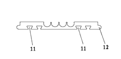
A kind of finned radiator of the utility model, like Fig. 1 ~ shown in Figure 4, it comprises base 1, a plurality of radiating fin 2; Base 1 is aluminium, copper or other Heat Conduction Materials, and the bottom surface of base 1 is placed on the product that needs heat radiation, and said bottom surface is to be reference with Fig. 2; Correspondingly, to be provided with the one side of groove 11 be last end face to base 1 among Fig. 2, and radiating fin 2 roots connect the last end face of base 1; Radiating fin 2 roots are extended with shackle member 21, and the groove 11 of end face is corresponding with shackle member 21 on the base 1, during use; Shackle member 21 and groove 11 clampings, thus make radiating fin 2 be fixedly connected base 1, and a plurality of radiating fin 2 stacked arrangement form radiating fin group 3.As shown in Figure 4; Shackle member 21 is defined as connecting portion 211 near the part of radiating fin 2 roots; Shackle member 21 free external parts are defined as Access Division 212; Access Division 212 connects said radiating fin 2 roots through connecting portion 211, is connected reliably with base 1 in order to make shackle member 21, and the Breadth Maximum of Access Division 212 is greater than the minimum widith of connecting portion 211.Fig. 3, shown in Figure 4 be a kind of preferred implementation of the utility model; Shackle member 21 is trapezoidal, and this trapezoidal long base is positioned at Access Division 212, and radiating fin 2 is connected with base 1 reliably; Make that also the area of shackle member 21 is bigger, improve the intensity of shackle member 21.Certainly, shackle member 21 also can be other shapes, and shackle member 21 as shown in Figure 5 is be connected with radiating fin 2 cylindrical, and shackle member 21 shown in Figure 6 is " L " shape.When the quantity of shackle member 21 during at least two, for example shackle member 21 is a rectangle, and shackle member 21 is two, and the side of two draw-in grooves 21 is not parallel, also can play the effect of fixed radiator fin 2.But shackle member 21 punch formings of the radiating fin 2 of the utility model; Shackle member 21 is connected in the groove 11 through punching press, thereby makes radiating fin 2 be connected fast with base 1, and radiating fin 2 is big with the contact area of base 1; But quick conductive, thereby improve heat transfer efficiency.
Further, like Fig. 1, shown in Figure 2, the finned radiator of the utility model is provided with heat pipe 6; Heat pipe 6 one ends pass radiating fin group 3; The other end connects base 1, and heat pipe 6 can strengthen heat radiation on the one hand, also can connect radiating fin 2 and base 1 on the other hand.
Further; Like Fig. 3, shown in Figure 4, base 1 two side is respectively arranged with embedding hook 12, and radiating fin 2 roots are provided with link slot 22; Shackle member 21 is arranged in the link slot 22; Link slot 22 is provided with the chimeric groove 221 with embedding hook 12 clampings, and embedding hook 12 and chimeric groove 221 mutual clampings make base 1 be connected more reliable with radiating fin 2.
Further, as shown in Figure 4, the position that link slot 22 is connected with base 1 is provided with clip 7, and clip 7 is conflicted and connected base 1, thereby can increase the contact area of radiating fin 2 and base 1, makes radiating effect better.
As shown in Figure 4, shackle member 21 is provided with bending part 213, and bending part 213 is conflicted with groove 11 and is connected, and bending part 213 has strengthened the intensity of shackle member 21, makes it not yielding.
embodiment two.
The finned radiator of the utility model can be used with fan, to strengthen heat radiation, when using fan; Air can only be along the channel flow between the adjacent radiating fin 2, and air can not flow along the direction perpendicular to passage, thereby causes the radiating effect of this direction relatively poor; In order to address this problem, as shown in Figure 5, radiating fin 2 is provided with ventilation hole 4; Air can flow along ventilation hole 41, thereby takes away heat, improves radiating efficiency.Other parts of present embodiment are identical with embodiment one.
Further; As shown in Figure 6, groove 11 bottoms of base 1 are provided with first ventilation slot 5, and air can flow along first ventilation slot 5; Thereby take away heat; In order to strengthen heat radiation, radiating fin 2 is provided with recess, makes draught area bigger thereby this recess and first ventilation slot 5 are spliced to form ventilation hole 4.
embodiment three.
For the finned radiator of the utility model, when using fan to strengthen heat radiation, air can be along the channel flow between the adjacent radiating fin 2; And for groove 11 parts of base 1, air is difficult to outwards flow, and causes the radiating effect at this position relatively poor; In order to address this problem; As shown in Figure 7, base 1 is provided with second ventilation slot, 8, the second ventilation slots 8 and is positioned at groove 11 bottoms; Second ventilation slot 8 is between adjacent two radiating fins 2, and other parts of present embodiment are identical with embodiment.
embodiment four.
Radiating fin 2 is thinner, therefore through shackle member 12 be connected with base 1 possibly cause connecting insecure.As shown in Figure 8, radiating fin 2 is provided with draw-in groove 23, and base 1 is extended with second shackle member 13 that cooperates with draw-in groove 23, draw-in groove 23 and 13 clampings of second shackle member.Can make base 1 be connected more firm through second shackle member 13 with radiating fin 2.Second shackle member 13 comprises that second connecting portion 131,132, the second Access Divisions 132, second Access Division connect the minimum widith of the Breadth Maximum of bases 1, the second Access Division 132 greater than second connecting portion 131 through second connecting portion 131.Be illustrated in figure 9 as the another execution mode of the finned radiator of present embodiment.
It is to be noted; Base 1 is not limited to shape, the structure that the foregoing description is explained with radiating fin 2, and shown in figure 10 is another execution mode of the utility model, similar to the above embodiments; Base 1 is provided with two grooves 11, two second shackle member 13; Radiating fin 2 be provided with two shackle member 21, two 23, two grooves 11 of draw-in groove respectively with the 21 corresponding connections of two shackle member, two second shackle member 13 respectively with the 23 corresponding connections of two draw-in grooves.
Should be noted that at last; Above embodiment is only in order to explain the technical scheme of the utility model; But not to the restriction of the utility model protection range, although with reference to preferred embodiment the utility model has been done explanation at length, those of ordinary skill in the art is to be understood that; Can make amendment or be equal to replacement the technical scheme of the utility model, and not break away from the essence and the scope of the utility model technical scheme.
Claims (10)
1. finned radiator; Comprise base (1), a plurality of radiating fin (2); It is characterized in that: said radiating fin (2) root connects said base (1), and said radiating fin (2) root is extended with shackle member (21), and said base (1) is provided with and said shackle member (21) corresponding groove (11); Said shackle member (21) and said groove (11) clamping, said a plurality of radiating fins (2) stacked arrangement forms radiating fin group (3).
2. a kind of finned radiator according to claim 1; It is characterized in that: said shackle member (21) comprises connecting portion (211), Access Division (212); Said Access Division (212) connects said radiating fin (2) root through said connecting portion (211), and the Breadth Maximum of said Access Division (212) is greater than the minimum widith of said connecting portion (211).
3. a kind of finned radiator according to claim 2 is characterized in that: said shackle member (21) is provided with bending part (213), and said bending part (213) is conflicted with said groove (11) and is connected.
4. a kind of finned radiator according to claim 2 is characterized in that: said radiating fin (2) is provided with ventilation hole (4).
5. according to a kind of finned radiator shown in the claim 2, it is characterized in that: said base (1) is provided with first ventilation slot (5).
6. a kind of finned radiator according to claim 2 is characterized in that: said base (1) is provided with second ventilation slot (8), and said second ventilation slot (8) is positioned between adjacent two said radiating fins (2).
7. a kind of finned radiator according to claim 2 is characterized in that: further be provided with heat pipe (6), said heat pipe (6) one ends pass said radiating fin group (3), and the other end connects said base (1).
8. a kind of finned radiator according to claim 7; It is characterized in that: said base (1) two side is respectively arranged with embedding hook (12); Said radiating fin (2) root is provided with link slot (22); Said shackle member (21) is arranged in the said link slot (22), and said link slot (22) is provided with the chimeric groove (221) with said embedding hook (12) clamping.
9. according to any described a kind of finned radiator of claim 1 ~ 8; It is characterized in that: said radiating fin (2) is provided with draw-in groove (23); Said base (1) is extended with second shackle member (13) that cooperates with said draw-in groove (23), said draw-in groove (23) and said second shackle member (13) clamping.
10. a kind of finned radiator according to claim 9; It is characterized in that: said second shackle member (13) comprises second connecting portion (131), second Access Division (132); Said second Access Division (132) connects said base (1) through said second connecting portion (131), and the Breadth Maximum of said second Access Division (132) is greater than the minimum widith of said second connecting portion (131).
Priority Applications (3)
| Application Number | Priority Date | Filing Date | Title |
|---|---|---|---|
| CN2011202875739U CN202168320U (en) | 2011-08-09 | 2011-08-09 | Fin type radiating device |
| TW100215437U TWM427766U (en) | 2011-08-09 | 2011-08-19 | Finned heat sinks |
| JP2011005177U JP3171781U (en) | 2011-08-09 | 2011-09-05 | Fin type radiator |
Applications Claiming Priority (1)
| Application Number | Priority Date | Filing Date | Title |
|---|---|---|---|
| CN2011202875739U CN202168320U (en) | 2011-08-09 | 2011-08-09 | Fin type radiating device |
Publications (1)
| Publication Number | Publication Date |
|---|---|
| CN202168320U true CN202168320U (en) | 2012-03-14 |
Family
ID=45804121
Family Applications (1)
| Application Number | Title | Priority Date | Filing Date |
|---|---|---|---|
| CN2011202875739U Expired - Fee Related CN202168320U (en) | 2011-08-09 | 2011-08-09 | Fin type radiating device |
Country Status (3)
| Country | Link |
|---|---|
| JP (1) | JP3171781U (en) |
| CN (1) | CN202168320U (en) |
| TW (1) | TWM427766U (en) |
Cited By (2)
| Publication number | Priority date | Publication date | Assignee | Title |
|---|---|---|---|---|
| CN103495677A (en) * | 2013-10-10 | 2014-01-08 | 昆山纯柏精密五金有限公司 | Method for machining finned radiator |
| CN108770304A (en) * | 2018-06-27 | 2018-11-06 | 江苏英杰电子器件有限公司 | A kind of Split radiator cover board |
-
2011
- 2011-08-09 CN CN2011202875739U patent/CN202168320U/en not_active Expired - Fee Related
- 2011-08-19 TW TW100215437U patent/TWM427766U/en unknown
- 2011-09-05 JP JP2011005177U patent/JP3171781U/en not_active Expired - Fee Related
Cited By (2)
| Publication number | Priority date | Publication date | Assignee | Title |
|---|---|---|---|---|
| CN103495677A (en) * | 2013-10-10 | 2014-01-08 | 昆山纯柏精密五金有限公司 | Method for machining finned radiator |
| CN108770304A (en) * | 2018-06-27 | 2018-11-06 | 江苏英杰电子器件有限公司 | A kind of Split radiator cover board |
Also Published As
| Publication number | Publication date |
|---|---|
| JP3171781U (en) | 2011-11-17 |
| TWM427766U (en) | 2012-04-21 |
Similar Documents
| Publication | Publication Date | Title |
|---|---|---|
| WO2014180323A1 (en) | Heat exchanger | |
| CN202168320U (en) | Fin type radiating device | |
| CN202143342U (en) | Fin type radiator for enhancing heat radiation | |
| CN202143335U (en) | Fin-type radiator of improved structure | |
| US20080202726A1 (en) | Fastening structure for combining heat conducting pipe and fins | |
| CN102291965A (en) | Manufacturing method for fin-type radiator | |
| CN204892789U (en) | Heat sink assembly | |
| CN205028894U (en) | Gear shaping formula welding heat pipe cooling ware | |
| CN101522010B (en) | Heat dissipating device and manufacturing method thereof | |
| CN102999131B (en) | Radiator fins and substrate stamping combined method | |
| CN204564959U (en) | A kind of fin-inserted radiator riveting tool | |
| CN211503813U (en) | Cooling tube plate | |
| CN104923689A (en) | Heat dissipation module manufacturing method and heat dissipation module | |
| TWM421693U (en) | Fin heat sink structure improvement | |
| CN102256475A (en) | Fin type radiator with improved structure | |
| CN204272573U (en) | One is exempted to weld finned radiator | |
| CN216282975U (en) | Rectangular staggered-tooth radiating fin | |
| CN206711889U (en) | A kind of IGBT coolers | |
| CN207266487U (en) | Venetian blind type fin radiator | |
| CN214046495U (en) | Heat dissipation combined structure and heat dissipation device | |
| CN208462264U (en) | A kind of double-sided substrate corrugated teeth module heat radiator | |
| CN203734984U (en) | Radiator for large-power electronic device | |
| CN210602950U (en) | Aluminum plate type heat exchanger radiating fin | |
| CN213120217U (en) | Heat pipe stacking heat conduction and dissipation device | |
| CN210689335U (en) | Heat exchange fin assembly, heat exchanger with same and gas water heater |
Legal Events
| Date | Code | Title | Description |
|---|---|---|---|
| C14 | Grant of patent or utility model | ||
| GR01 | Patent grant | ||
| CF01 | Termination of patent right due to non-payment of annual fee |
Granted publication date: 20120314 Termination date: 20170809 |
|
| CF01 | Termination of patent right due to non-payment of annual fee |