CN202132730U - LED lamp tube - Google Patents
LED lamp tube Download PDFInfo
- Publication number
- CN202132730U CN202132730U CN201120123991U CN201120123991U CN202132730U CN 202132730 U CN202132730 U CN 202132730U CN 201120123991 U CN201120123991 U CN 201120123991U CN 201120123991 U CN201120123991 U CN 201120123991U CN 202132730 U CN202132730 U CN 202132730U
- Authority
- CN
- China
- Prior art keywords
- support
- led
- fluorescent tube
- socket
- plug
- Prior art date
- Legal status (The legal status is an assumption and is not a legal conclusion. Google has not performed a legal analysis and makes no representation as to the accuracy of the status listed.)
- Expired - Fee Related
Links
Images


Classifications
-
- F—MECHANICAL ENGINEERING; LIGHTING; HEATING; WEAPONS; BLASTING
- F21—LIGHTING
- F21S—NON-PORTABLE LIGHTING DEVICES; SYSTEMS THEREOF; VEHICLE LIGHTING DEVICES SPECIALLY ADAPTED FOR VEHICLE EXTERIORS
- F21S2/00—Systems of lighting devices, not provided for in main groups F21S4/00 - F21S10/00 or F21S19/00, e.g. of modular construction
- F21S2/005—Systems of lighting devices, not provided for in main groups F21S4/00 - F21S10/00 or F21S19/00, e.g. of modular construction of modular construction
-
- F—MECHANICAL ENGINEERING; LIGHTING; HEATING; WEAPONS; BLASTING
- F21—LIGHTING
- F21S—NON-PORTABLE LIGHTING DEVICES; SYSTEMS THEREOF; VEHICLE LIGHTING DEVICES SPECIALLY ADAPTED FOR VEHICLE EXTERIORS
- F21S4/00—Lighting devices or systems using a string or strip of light sources
- F21S4/20—Lighting devices or systems using a string or strip of light sources with light sources held by or within elongate supports
- F21S4/28—Lighting devices or systems using a string or strip of light sources with light sources held by or within elongate supports rigid, e.g. LED bars
-
- F—MECHANICAL ENGINEERING; LIGHTING; HEATING; WEAPONS; BLASTING
- F21—LIGHTING
- F21V—FUNCTIONAL FEATURES OR DETAILS OF LIGHTING DEVICES OR SYSTEMS THEREOF; STRUCTURAL COMBINATIONS OF LIGHTING DEVICES WITH OTHER ARTICLES, NOT OTHERWISE PROVIDED FOR
- F21V21/00—Supporting, suspending, or attaching arrangements for lighting devices; Hand grips
- F21V21/005—Supporting, suspending, or attaching arrangements for lighting devices; Hand grips for several lighting devices in an end-to-end arrangement, i.e. light tracks
-
- F—MECHANICAL ENGINEERING; LIGHTING; HEATING; WEAPONS; BLASTING
- F21—LIGHTING
- F21V—FUNCTIONAL FEATURES OR DETAILS OF LIGHTING DEVICES OR SYSTEMS THEREOF; STRUCTURAL COMBINATIONS OF LIGHTING DEVICES WITH OTHER ARTICLES, NOT OTHERWISE PROVIDED FOR
- F21V23/00—Arrangement of electric circuit elements in or on lighting devices
- F21V23/06—Arrangement of electric circuit elements in or on lighting devices the elements being coupling devices, e.g. connectors
-
- F—MECHANICAL ENGINEERING; LIGHTING; HEATING; WEAPONS; BLASTING
- F21—LIGHTING
- F21Y—INDEXING SCHEME ASSOCIATED WITH SUBCLASSES F21K, F21L, F21S and F21V, RELATING TO THE FORM OR THE KIND OF THE LIGHT SOURCES OR OF THE COLOUR OF THE LIGHT EMITTED
- F21Y2105/00—Planar light sources
- F21Y2105/10—Planar light sources comprising a two-dimensional array of point-like light-generating elements
-
- F—MECHANICAL ENGINEERING; LIGHTING; HEATING; WEAPONS; BLASTING
- F21—LIGHTING
- F21Y—INDEXING SCHEME ASSOCIATED WITH SUBCLASSES F21K, F21L, F21S and F21V, RELATING TO THE FORM OR THE KIND OF THE LIGHT SOURCES OR OF THE COLOUR OF THE LIGHT EMITTED
- F21Y2115/00—Light-generating elements of semiconductor light sources
- F21Y2115/10—Light-emitting diodes [LED]
Landscapes
- Engineering & Computer Science (AREA)
- General Engineering & Computer Science (AREA)
- Non-Portable Lighting Devices Or Systems Thereof (AREA)
- Arrangement Of Elements, Cooling, Sealing, Or The Like Of Lighting Devices (AREA)
Abstract
Provided is an LED lamp tube, including a support, an LED module, a lamp shade and an LED driving power; the LED driving power is disposed in a support; the LED module is mounted on the support; the lamp shade is fixed by the support and covers the LED module; sockets are provided on lateral faces of the support; a fitted plug can be mounted in the socket; end caps for enclosing the support and the lamp shade are fixed on two ends of the support; that the lamp tube is electrically connected with an external power is realized through engagement of the socket provided on the lateral face of the support and the plug; therefore, the LED lamp tube is convenient to fix, connect and expand; especially, when a plurality of lamp tubes are combined and arranged in a line, adjacent lamp tubes are suspension-jointed in a gapless way through engagement of the sockets and the plugs provided on the lateral faces. The LED lamp tubes are convenient to mount and fix, have attractive appearance, form a gapless light band especially in wholly lighting and emit ideal and integral light rays.
Description
Technical field
The utility model relates to a kind of LED light fixture, especially a kind of LED fluorescent tube.
Background technology
Because led light source energy-conservation, the many advantages such as luminous efficiency good, long service life that possess, begun at present to be accepted widely and popularize by the market, one type of LED fluorescent tube is wherein arranged, be exclusively used in and substitute traditional fluorescent lamp.
Fluorescent lamp is as a kind of lighting commonly used; Commonly be used in family or various public occasion, and traditional fluorescent lamp because possessing toxicity, endangers to some extent to environment and health its raw material; Therefore as the LED fluorescent tube of replace fluorescent lamps; Except having advantages such as energy saving, luminous efficiency is good, the life-span is long, can also avoid toxic pollution, can be described as a kind of very good fluorescent lamp substitute.
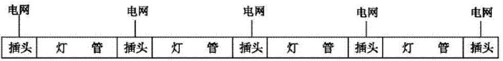
Yet for the spot field; Adopt LED also can some inferior position occur because of its characteristic as light source; It mainly is presented as, because LED is a spot light, luminous continuity is not enough to some extent when being combined as the line source structure; Though this deficiency can remedy through increasing LED density and improving the positive lens arrangement of fluorescent tube, also only is confined in the wall scroll fluorescent tube; And many fluorescent tubes use to increase length of illumination if desired; Then, between fluorescent tube and fluorescent tube, just need leave bigger distance and be connected external power grid because the lamp holder at light two ends needs to use as the plug that connect electricity, so then as shown in Figure 1; Still can there be bigger non-luminous zone between fluorescent tube of combining and the fluorescent tube; Be reflected in the irradiation place, the bright and dark light inequality will occur, problem such as illuminating effect is bad.
Be directed to these problems, personnel have carried out a series of improvement to the connectivity scenario of LED fluorescent tube in the field, for example in supply socket; Be designed to mutual mode of pegging graft between the adjacent fluorescent tube, introducing civil power by previous fluorescent tube is a back lamp tube power supply, the i.e. two ends of fluorescent tube; One end is that positive connector one end is cloudy connector, when being combined as longitudinal light source, only needs the fluorescent tube of sufficient amount to be plugged on together from beginning to end successively like this; And get final product by first and/or last fluorescent tube outside electric power network, yet, adopt this structure a series of weak points still to occur; Mainly be presented as: the disposable connection of multistage fluorescent tube, therefore after length, the quantity of fluorescent lamp are connected in series to certain value, just can not continue to increase prolongation again; Otherwise can make that the power in whole loop is excessive, burn out fluorescent tube or power supply; That is to say that the elongatedness of this scheme is limited, have only at present fluorescent tube is divided into two-way or multichannel more, and stagger each other and connect power supply; Could guarantee to connect separately power supply, its configuration state is as shown in Figure 2, yet so; Not only make fluorescent lamp integral installation inconvenience, and the fluorescent tube that staggers each other is when luminous, light is not obviously not point-blank; Can not form continuous, a unified light belt, cause uneven illumination to spare and do not plan a successor, the problem of overall appearance degree occur influencing; Adopt such scheme in addition; Do not have enough nargin between the then whole rectangular fluorescent tube both sides supply socket, need if one of them fluorescent tube breaks down to change, remove whole section fluorescent tube that links together earlier with regard to having to; Pull down the fault fluorescent tube again; Qualified product in the replacing, thus, safeguard and change will be very inconvenience.
Summary of the invention
To the problems referred to above, the utility model provides a kind of electric connection structure reasonable, is convenient to a plurality of fitting together, and it is convenient to install and change, and can form a perfect light belt, the good unfaulted LED fluorescent tube of radiation response when luminous.
The utility model is that the technical scheme that its technical problem of solution is adopted is:
A kind of LED fluorescent tube comprises support, LED module, lampshade and LED driving power; The LED driving power is arranged in the support; The LED module is installed on the support, and the LED module fixed and covered by lampshade by support, and said cradle is provided with socket; Can be fitted with the plug that is complementary on the socket, said support two ends are fixed with the plug of blocking support and lampshade.
The beneficial effect of the utility model is: in the utility model, the external electricity of fluorescent tube is to realize through the socket mated plug that is arranged at cradle; Lamp tube ends then is provided with plug, is not used in to connect electricity, so can realize more convenient fixing, wiring and expansion; Especially when synthetic rectangular uses of some light tube group, adjacent fluorescent tube can not have the gap and hangs and be connected together, and mutual connection is then realized by the socket plug of side; So not only install and fix conveniently, and profile is neat and artistic, especially when integral body is luminous; Can form a perfect light belt in no gap, the light effects that irradiates is desirable, no tomography; Under this state, pull down one of them fluorescent tube if desired in addition, then only need pull up the pairing plug of this tube stand side just can, and can other fluorescent tubes not impacted, visible, installation of the utility model and dismounting, replacing are with more convenient.
In addition, the utility model can also improve as follows:
Support slightly is longer than in above-mentioned lampshade and LED module end, and the plug bottom is one to be placed in the fixing terminal of bracket end, and plug top is the thin slice of sealing the lampshade end.Can fix the desirable encapsulation of lamp tube ends.
The support side faces at both ends respectively is provided with a socket, and wherein first socket is electrically connected the LED driving power, and second socket and first socket are electrically connected.So when a plurality of fluorescent tubes connect successively, can connect successively, all fluorescent tubes are together in parallel, realize wiring and expansion easily by the socket plug of each fluorescent tube.
Above-mentioned thin slice is a transparent member, more helps eliminating the dark space between the adjacent fluorescent tube.
Description of drawings
Be further described below in conjunction with the accompanying drawing and the specific embodiment:
Fig. 1 is the combining structure sketch map of a plurality of fluorescent tubes in the prior art;
Fig. 2 is the combining structure sketch map of a plurality of fluorescent tubes in a kind of improvement project of prior art;
Fig. 3 is the perspective view of the utility model;
Fig. 4 is the fractionation structural representation of the utility model;
Fig. 5 is the utility model cross-sectional view;
Fig. 6 is the combining structure sketch map of fluorescent tube among a kind of embodiment of the utility model;
Fig. 7 is a fluorescent tube combination structural representation among the another kind of embodiment of the utility model.
The specific embodiment
Like Fig. 2 and shown in Figure 4, a kind of LED fluorescent tube that the utility model provided comprises support 1; LED module 2, lampshade 3 and LED driving power 4, wherein LED driving power 4 is arranged in the support 1, and LED module 2 is installed on the support 1; Lampshade 3 is fixed by support 1 and is covered LED module 2, and support 1 side is provided with socket 5; Can be fitted with the plug 6 that is complementary on the socket 5, plug 6 can outside electric power network, be that LED module 2 is supplied power through LED driving power 4; The light that LED module 2 sends is then appeared by lampshade 3, is the external light illumination that provides; These external support 1 two ends are fixed with the plug 7 of blocking support 1 and lampshade 3, reach effects such as auxiliary fixing, dustproof, waterproof.
As shown in Figure 5, as the preferred implementation of the utility model, support 1 slightly is longer than in the end of lampshade 3 and LED module 2; Said plug 7 bottoms are one to be placed in the fixing terminal 71 of support 1 end; Said plug 7 tops are the thin slice 72 of sealing lampshade 3 ends, and fixing to be clamped by the fixing terminal 71 of plug 7 bottoms and support 1 end, the structure of lampshade 3 is blocked in 72 conducts of the thin slice on top; Like this when reaching better fixed effect; Can make plug 7 can not block the illumination effect of lamp tube end as far as possible, link together when using at two or many lamps, the blanking bar between the adjacent lamps can be eliminated basically; And, can make light pass thin slice 72 design transparent member as further improving, and under the fluorescent tube assembled state, can eliminate blanking bar fully like this, make two fluorescent tubes of combining, the light that sends is complete having no time as same complete fluorescent tube.
The superiority of the utility model is embodied in and installs and fixes and make up in the use; Especially lump together many light tube group, form occasion of long luminous zone, therefore; Socket 5 mated plug 6 on the support 1; Except connecing extraneous electrical network is led drive circuit 4 power supply, also can play with adjacent fluorescent tube outstanding and connect effect, and so its cabling mode can be designed to: support 1 side faces at both ends respectively is provided with a socket 5; Wherein first socket 5 is electrically connected 4, the second sockets of LED driving power 5 and is electrically connected with first socket 5.When reality was used, its fixed form can be an example with the fluorescent tube of end and a fluorescent tube that is adjacent like Fig. 6 and shown in Figure 7, and the fluorescent tube of end and adjacent fluorescent tube linearly are arranged together, between the two only across separately plug 7; In the fluorescent tube of end, first socket 5 is by plug 6 outside electric power network of institute's plug-in mounting, and in fluorescent tube; A circuit of this socket 5 is connected to led drive circuit 4; By led drive circuit 4 is LED module 2 power supply, and another circuit then is directly connected to second socket 5 of the fluorescent tube other end; Simultaneously; Plug 6 its other ends that are plugged in second socket 5 also are plugged in first socket 5 of two fluorescent tubes by another plug 6, like this cabling of electrical network is just along first socket 5 of first fluorescent tube; To second socket 5, again to first socket 5 of second fluorescent tube; Be equivalent in first fluorescent tube, electrical network is told a special line to this second lamp tube power supply; Same, in second fluorescent tube, second socket 5 with dividing line to the second fluorescent tube again is used to connect next fluorescent tube; And the like, then can be in nominal load the abundant fluorescent tube of parallel connection, reached the effect of all the other fluorescent tubes behind first fluorescent tube being hidden cabling simultaneously; In addition, in this mode of connection, the LED module 2 of a fluorescent tube or led drive circuit 4 faults and can not be luminous the time, can't influence the luminous of other fluorescent tubes.
Therefore; In the embodiment that provides like Fig. 6, a plurality of fluorescent tubes are along straight line adjacent the arranging together of head and the tail each other, and each fluorescent tube all connects to come power taking through socket 5, the plug 6 of end side separately; Interconnect on the formation physical arrangement, but the non-interfering syntagmatic of circuit; So not only monnolithic case is attractive in appearance, and owing to seamless outstanding being connected together between the fluorescent tube, when luminous, can form a perfect light belt, and the light effects that irradiates is desirable, no tomography.
And consider loading problem and safety problem, and can also on the basis of embodiment that Fig. 6 gives, do further to improve, for example shown in Figure 7; The wiring of any two fluorescent tubes in the one whole piece fluorescent tube band is interrupted; A next fluorescent tube is got access to grid by plug 6 lead-out wires separately, and its practical effect all is the same, but can make that so two parts fluorescent tube does not disturb mutually; Alleviate power source loads; Electricity consumption is safer, and this fit on support 1 side is provided with the structure of socket 5, and its wiring and installation be the convenience of ten minutes also.
Claims (4)
1. LED fluorescent tube; Comprise support (1); LED module (2), lampshade (3) and LED driving power (4), LED driving power (4) are arranged in the support (1), and LED module (2) is installed on the support (1); LED module (2) is fixed and covered to lampshade (3) by support (1); It is characterized in that: said support (1) side is provided with socket (5), the plug (6) that can plug-in mounting on the socket (5) be complementary, and said support (1) two ends are fixed with the plug (7) of blocking support (1) and lampshade (3).
2. a kind of LED fluorescent tube according to claim 1; It is characterized in that: support (1) slightly is longer than in said lampshade (3) and LED module (2) end; Said plug (7) bottom is one to be placed in the fixing terminal (71) of support (1) end, and said plug (7) top is the thin slice (72) of sealing lampshade (3) end.
3. a kind of LED fluorescent tube according to claim 1 and 2; It is characterized in that: said support (1) side faces at both ends respectively is provided with a socket (5); Wherein first socket (5) is electrically connected LED driving power (4), and second socket (5) is electrically connected with first socket (5).
4. a kind of LED fluorescent tube according to claim 2 is characterized in that: said thin slice (72) is a transparent member.
Priority Applications (2)
| Application Number | Priority Date | Filing Date | Title |
|---|---|---|---|
| CN201120123991U CN202132730U (en) | 2011-04-25 | 2011-04-25 | LED lamp tube |
| PCT/CN2011/075405 WO2012145950A1 (en) | 2011-04-25 | 2011-06-07 | Led lamp tube |
Applications Claiming Priority (1)
| Application Number | Priority Date | Filing Date | Title |
|---|---|---|---|
| CN201120123991U CN202132730U (en) | 2011-04-25 | 2011-04-25 | LED lamp tube |
Publications (1)
| Publication Number | Publication Date |
|---|---|
| CN202132730U true CN202132730U (en) | 2012-02-01 |
Family
ID=45521497
Family Applications (1)
| Application Number | Title | Priority Date | Filing Date |
|---|---|---|---|
| CN201120123991U Expired - Fee Related CN202132730U (en) | 2011-04-25 | 2011-04-25 | LED lamp tube |
Country Status (2)
| Country | Link |
|---|---|
| CN (1) | CN202132730U (en) |
| WO (1) | WO2012145950A1 (en) |
Cited By (8)
| Publication number | Priority date | Publication date | Assignee | Title |
|---|---|---|---|---|
| CN102705739A (en) * | 2012-06-01 | 2012-10-03 | 惠州市洲明节能科技有限公司 | LED fluorescent lamp, LED fluorescent lamp bracket and LED fluorescent lamp combination |
| CN104075163A (en) * | 2014-07-11 | 2014-10-01 | 扬益电子科技(宁波)有限公司 | LED lamp integrating wiring groove and lamp body |
| CN105882133A (en) * | 2016-04-15 | 2016-08-24 | 郑舜川 | Shutter type lamp box |
| CN106195692A (en) * | 2016-08-30 | 2016-12-07 | 江门市英特视界科技有限公司 | One not band edge embedded type seamless connects LED line |
| CN107005009A (en) * | 2015-04-24 | 2017-08-01 | 陈锦焜 | Socket-type light fixture and its socket |
| CN107166205A (en) * | 2017-03-31 | 2017-09-15 | 李峰 | One kind is without high pole street lamp |
| CN109668066A (en) * | 2019-02-18 | 2019-04-23 | 广东科而美光电有限公司 | A kind of lamps and lanterns convenient for assembling |
| CN109899717A (en) * | 2019-03-29 | 2019-06-18 | 深圳市鑫盛凯光电有限公司 | A kind of fast-connecting type modularized limit emitting diode (LED) lamp bar |
Families Citing this family (1)
| Publication number | Priority date | Publication date | Assignee | Title |
|---|---|---|---|---|
| CN113464856A (en) * | 2020-03-14 | 2021-10-01 | 鲍德金 | Human body infrared induction lamp tube |
Family Cites Families (6)
| Publication number | Priority date | Publication date | Assignee | Title |
|---|---|---|---|---|
| CN2680978Y (en) * | 2003-09-29 | 2005-02-23 | 奥迪通用照明(广州)有限公司 | Shadowless light band support bracket lighting apparatus |
| US20080165530A1 (en) * | 2007-01-10 | 2008-07-10 | Westerveld Johannes Hendrikus | Illuminative apparatus |
| CN201041307Y (en) * | 2007-04-30 | 2008-03-26 | 蔡焯桂 | Daylight lamp fixture |
| CN201731287U (en) * | 2009-12-25 | 2011-02-02 | 深圳市通普科技有限公司 | LED fluorescent lamp |
| CN201811044U (en) * | 2010-09-03 | 2011-04-27 | 罗东 | Fluorescent lamp |
| CN201779629U (en) * | 2010-09-22 | 2011-03-30 | 浙江捷莱照明有限公司 | LED strip-shaped lamp end cover |
-
2011
- 2011-04-25 CN CN201120123991U patent/CN202132730U/en not_active Expired - Fee Related
- 2011-06-07 WO PCT/CN2011/075405 patent/WO2012145950A1/en active Application Filing
Cited By (11)
| Publication number | Priority date | Publication date | Assignee | Title |
|---|---|---|---|---|
| CN102705739A (en) * | 2012-06-01 | 2012-10-03 | 惠州市洲明节能科技有限公司 | LED fluorescent lamp, LED fluorescent lamp bracket and LED fluorescent lamp combination |
| CN102705739B (en) * | 2012-06-01 | 2014-08-20 | 广东洲明节能科技有限公司 | LED fluorescent lamp combination |
| CN104075163A (en) * | 2014-07-11 | 2014-10-01 | 扬益电子科技(宁波)有限公司 | LED lamp integrating wiring groove and lamp body |
| CN107005009A (en) * | 2015-04-24 | 2017-08-01 | 陈锦焜 | Socket-type light fixture and its socket |
| CN105882133A (en) * | 2016-04-15 | 2016-08-24 | 郑舜川 | Shutter type lamp box |
| CN105882133B (en) * | 2016-04-15 | 2018-11-30 | 浙江舜嘉通用设备有限公司 | A kind of shutter type lamp box |
| CN106195692A (en) * | 2016-08-30 | 2016-12-07 | 江门市英特视界科技有限公司 | One not band edge embedded type seamless connects LED line |
| CN107166205A (en) * | 2017-03-31 | 2017-09-15 | 李峰 | One kind is without high pole street lamp |
| CN109668066A (en) * | 2019-02-18 | 2019-04-23 | 广东科而美光电有限公司 | A kind of lamps and lanterns convenient for assembling |
| CN109899717A (en) * | 2019-03-29 | 2019-06-18 | 深圳市鑫盛凯光电有限公司 | A kind of fast-connecting type modularized limit emitting diode (LED) lamp bar |
| CN109899717B (en) * | 2019-03-29 | 2022-03-11 | 深圳市鑫盛凯光电有限公司 | Quick-connection type modular LED lamp strip |
Also Published As
| Publication number | Publication date |
|---|---|
| WO2012145950A1 (en) | 2012-11-01 |
Similar Documents
| Publication | Publication Date | Title |
|---|---|---|
| CN202132730U (en) | LED lamp tube | |
| CN105805600A (en) | LED lamp with loudspeakers | |
| CN202382128U (en) | LED down lamp structure | |
| CN205424487U (en) | All -round three -dimensional illumination LED filament lamp | |
| CN202195326U (en) | LED (light-emitting diode) lamp tube | |
| CN201437916U (en) | Multi-faceted LED daylight lamp | |
| CN202647536U (en) | Focusing type rechargeable desk lamp | |
| CN201836801U (en) | LED strobe lamp for stages | |
| CN208535788U (en) | A kind of LED downlight mould group for maintaining easily and replacing | |
| CN201885093U (en) | Light emitting diode (LED) cabinet lamp | |
| CN201811044U (en) | Fluorescent lamp | |
| CN206176092U (en) | LED photovoltaic module | |
| CN217329576U (en) | A concatenation formula LED electricity-saving lamp for computer lab intelligence cabinet | |
| CN201437925U (en) | Ladder-shaped lamp | |
| CN220061587U (en) | Combined lamp | |
| CN101619816B (en) | Ladder-shaped lamp | |
| CN215215880U (en) | Combined lighting lamp | |
| CN210004348U (en) | Combined lamp | |
| CN216079655U (en) | Light guide lamp strip structure | |
| CN103307516B (en) | Landscape lamp | |
| CN219510735U (en) | LED lamp set structure for socket | |
| CN202209556U (en) | LED lamp bulb | |
| CN201851930U (en) | LED (light-emitting diode) fluorescent lamp | |
| CN201386960Y (en) | LED street lighting lamp | |
| CN202012755U (en) | LED illumination lamp |
Legal Events
| Date | Code | Title | Description |
|---|---|---|---|
| C14 | Grant of patent or utility model | ||
| GR01 | Patent grant | ||
| C17 | Cessation of patent right | ||
| CF01 | Termination of patent right due to non-payment of annual fee |
Granted publication date: 20120201 Termination date: 20120425 |