CN202382128U - LED down lamp structure - Google Patents
LED down lamp structure Download PDFInfo
- Publication number
- CN202382128U CN202382128U CN2011204954260U CN201120495426U CN202382128U CN 202382128 U CN202382128 U CN 202382128U CN 2011204954260 U CN2011204954260 U CN 2011204954260U CN 201120495426 U CN201120495426 U CN 201120495426U CN 202382128 U CN202382128 U CN 202382128U
- Authority
- CN
- China
- Prior art keywords
- peg
- mentioned
- light
- emitting device
- connection
- Prior art date
- Legal status (The legal status is an assumption and is not a legal conclusion. Google has not performed a legal analysis and makes no representation as to the accuracy of the status listed.)
- Expired - Fee Related
Links
- 230000005540 biological transmission Effects 0.000 claims abstract description 18
- 239000004411 aluminium Substances 0.000 claims description 27
- 229910052782 aluminium Inorganic materials 0.000 claims description 27
- XAGFODPZIPBFFR-UHFFFAOYSA-N aluminium Chemical group [Al] XAGFODPZIPBFFR-UHFFFAOYSA-N 0.000 claims description 21
- 230000005855 radiation Effects 0.000 claims description 13
- 150000001398 aluminium Chemical class 0.000 claims description 6
- 238000004519 manufacturing process Methods 0.000 abstract description 5
- 230000000694 effects Effects 0.000 abstract description 3
- 230000000149 penetrating effect Effects 0.000 abstract 1
- 239000000463 material Substances 0.000 description 4
- 230000002950 deficient Effects 0.000 description 2
- 238000005516 engineering process Methods 0.000 description 2
- 230000004048 modification Effects 0.000 description 2
- 238000012986 modification Methods 0.000 description 2
- 239000004065 semiconductor Substances 0.000 description 2
- 208000033999 Device damage Diseases 0.000 description 1
- DGAQECJNVWCQMB-PUAWFVPOSA-M Ilexoside XXIX Chemical compound C[C@@H]1CC[C@@]2(CC[C@@]3(C(=CC[C@H]4[C@]3(CC[C@@H]5[C@@]4(CC[C@@H](C5(C)C)OS(=O)(=O)[O-])C)C)[C@@H]2[C@]1(C)O)C)C(=O)O[C@H]6[C@@H]([C@H]([C@@H]([C@H](O6)CO)O)O)O.[Na+] DGAQECJNVWCQMB-PUAWFVPOSA-M 0.000 description 1
- 230000009286 beneficial effect Effects 0.000 description 1
- 238000005282 brightening Methods 0.000 description 1
- 150000001875 compounds Chemical class 0.000 description 1
- 230000008034 disappearance Effects 0.000 description 1
- 230000005611 electricity Effects 0.000 description 1
- 230000004313 glare Effects 0.000 description 1
- 238000010438 heat treatment Methods 0.000 description 1
- 238000005286 illumination Methods 0.000 description 1
- 238000009434 installation Methods 0.000 description 1
- 229910001507 metal halide Inorganic materials 0.000 description 1
- 150000005309 metal halides Chemical class 0.000 description 1
- 238000000034 method Methods 0.000 description 1
- 229910052708 sodium Inorganic materials 0.000 description 1
- 239000011734 sodium Substances 0.000 description 1
- 239000007787 solid Substances 0.000 description 1
- 238000001228 spectrum Methods 0.000 description 1
Images


Landscapes
- Arrangement Of Elements, Cooling, Sealing, Or The Like Of Lighting Devices (AREA)
- Non-Portable Lighting Devices Or Systems Thereof (AREA)
Abstract
The utility model discloses an LED down lamp structure, which comprises a power supply device, a heat radiator and a light-emitting device, wherein the light-emitting device is detachably installed above the heat radiator, the power supply device is detachably installed below the heat radiator, a through hole penetrating the heat radiator is arranged in the heat radiator, a transmission line is installed in the through hole, each of the two ends of the transmission line is provided with a bayonet socket, a first bayonet cap is arranged in the power supply device, a second bayonet cap is arranged in the light-emitting device, and the first bayonet cap and the second bayonet cap are respectively inserted on the bayonet sockets on the two ends of the transmission line. In this way, the first bayonet cap and the second bayonet cap are respectively inserted on the two bayonet sockets of the transmission line so that the circuit of a down lamp is closed. Therefore, the power supply device and the light-emitting device of the LED down lamp can be replaced, and the LED down lamp has the characteristics of convenient use, material-saving effect, simple structure, convenient wiring and improvement of production efficiency.
Description
Technical field
The utility model relates to the lighting field technology, refers in particular to a kind of LED cylinder lamp structure.
Background technology
Down lamp is the light fixture of decorating on the roof, and it is widely used in the usefulness as accent light such as market, large supermarket, office space, hospital, school, hotel, high-end residential, but both brightening environment can beautify the environment again, be life increasing colour.The Down lamp that generally uses at present adopts metal halide lamp or fluorescent lamp as light source more.The general power consumption of this Down lamp is higher, heating is big, lamp tube service life is short, and photochromic soft inadequately, and it is dazzling that the human eye direct-view can be felt, even produce dazzle.
LED claims light emitting diode again, is to utilize the solid semiconductor chip as luminescent material, and when two ends add appropriate voltage, the son that dams in the semiconductor takes place compound, emits superfluous energy and causes that photo emissions produces visible light.The monochromaticjty of led light source luminous efficiency height and light is good, spectrum is narrow, need not to filter directly to send coloured visible light.Power consumption is few, and under the situation of same illuminating effect, power consumption is 1/8th of incandescent lamp bulb, 1/2nd of fluorescent tube.Long service life can reach 100,000 hours.And the material photochromic soft, that free from glare, not mercurous, sodium element etc. maybe health risks.Controllability is high, and built-in microprocessing systems can be controlled luminous intensity, regulates illumination mode, and it is color to demonstrate bright and colourful seven-colour-light, realizes light and artistic combining.
Though existing LED Down lamp has solved the some shortcomings that the Down lamp of conventional light source exists, also there is following defective the LED Down lamp in self: the light-emitting device of Down lamp lower end supply unit and upper end all is solidified as a whole with the Down lamp main body, can not change.After Down lamp power unit or light-emitting device damage, can not change it, cause Down lamp not re-use, and; The Down lamp complicated integral structure, wiring inconvenience influences production efficiency; To above defective, tackle its structure and improve, so that it is convenient in producing and using.
The utility model content
In view of this; The utility model is to the disappearance of prior art existence, and its main purpose provides a kind of LED cylinder lamp structure, and it can effectively solve existing LED Down lamp supply unit and light-emitting device all is solidified as a whole with the Down lamp main body; Can not change; And complex structure, wiring is inconvenient, influences the problem of production efficiency.
For realizing above-mentioned purpose, the utility model adopts following technical scheme:
A kind of LED cylinder lamp structure; Comprise supply unit, heat abstractor and light-emitting device, the dismountable heat abstractor top that is installed on of said light-emitting device, the dismountable heat abstractor below that is installed on of said supply unit; In heat abstractor, be provided with one run through heat abstractor through hole; One transmission line is installed in this through hole, and these transmission line two ends are respectively arranged with a plug socket, in supply unit, are provided with first connection-peg; In light-emitting device, be provided with second connection-peg, this first connection-peg and second connection-peg are plugged in respectively on the plug socket of above-mentioned transmission line two ends.
As a kind of preferred version: said supply unit comprises power pack and is installed on the pcb board in this power pack that above-mentioned first connection-peg is arranged on this pcb board, and this supply unit can be changed as required.
As a kind of preferred version: said power pack comprises upper cartridge body and lower box body, and this upper cartridge body and lower box body fasten and form a ccontaining cavity, and above-mentioned pcb board is installed in this ccontaining cavity.
As a kind of preferred version: be provided with a connector that upper cartridge body and lower box body are secured together between said upper cartridge body and the lower box body.
As a kind of preferred version: said heat abstractor is an aluminium extruded type heat radiation main body, and above-mentioned through hole vertically is arranged on this aluminium extruded type heat radiation main body.
As a kind of preferred version: be vertically arranged with two embedded grooves on the said aluminium extruded type heat radiation main body outer wall, in this two embedded groove, be separately installed with one be used to hang or install Down lamp fixed mount.
As a kind of preferred version: the A/F of said embedded groove is less than its inside groove width, and in the opening both sides respectively spacing be provided with laterally corresponding each other projection; The said fixing frame includes hook portion, Embedded Division and elastic portion, and wherein, this hook portion is used for the hook Down lamp, and this Embedded Division embeds in the above-mentioned embedded groove and is used for fixing fixed mount, and this elastic portion can be sheathed on the respective bump according to height needs two ends.
As a kind of preferred version: said light-emitting device includes the lamp tube, be installed in the lamp tube and have LED lamp group aluminium base, cover in the cover that lens and on the aluminium base are used for fixing lens; Above-mentioned second connection-peg is arranged on this aluminium base, and above-mentioned cover and aluminium base all can be changed as required.
The utility model compared with prior art has tangible advantage and beneficial effect; Particularly, can know, through with the dismountable heat abstractor below of being installed on of supply unit by technique scheme; With the dismountable heat abstractor top that is installed on of light-emitting device; And connection-peg is set respectively in supply unit and light-emitting device, and two plug sockets are set in heat abstractor, two connection-pegs are plugged in the conducting that realizes circuit on two plug sockets respectively.By this, this LED Down lamp, supply unit and light-emitting device can be changed, and convenient the use saved material, and simple in structure, and easy-to-connect has improved Down lamp production efficiency.
Be architectural feature and the effect of more clearly setting forth the utility model, come it is elaborated below in conjunction with accompanying drawing and specific embodiment.
Description of drawings
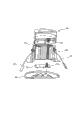
Fig. 1 is the assembling schematic perspective view of the utility model preferred embodiment;
Fig. 2 is the cross-sectional schematic of the utility model preferred embodiment;
Fig. 3 is the decomposing schematic representation of the utility model preferred embodiment.
The accompanying drawing identifier declaration:
10, supply unit 11, power pack
111, upper cartridge body 1111, spliced eye
112, lower box body 113, ccontaining cavity
114, connector 12, pcb board
121, first connection-peg 20, heat abstractor
21, aluminium extruded type heat radiation main body 211, through hole
212, transmission line 2121, plug socket
213, embedded groove 2131, opening
2132, projection 22, fixed mount
221, hook portion 222, Embedded Division
223, elastic portion 30, electro-heat equipment
31, lamp tube 311, containing groove
3111, open-work 32, aluminium base
321, second connection-peg 33, lens
34, cover.
The specific embodiment
The utility model such as Fig. 1 include supply unit 10, heat abstractor 20 and light-emitting device 30 to shown in Figure 3.
These supply unit 10 dismountable heat abstractor 20 tops that are installed on; It includes power pack 11 and is installed on the pcb board 12 in this power pack 11; Wherein, This power pack 10 comprises upper cartridge body 111 and lower box body 112, and this upper cartridge body 111 fastens with lower box body 112 and forms a ccontaining cavity 113, and above-mentioned pcb board 12 is installed in this ccontaining cavity 113; And between lower box body 112, be provided with one in upper cartridge body 111 and be used for connector 114 that upper cartridge body 111 and lower box body 112 are assembled into, be provided with a spliced eye 1111 in upper cartridge body 111; This pcb board 12 is provided with first connection-peg 121 that is used to conduct electricity, and this first connection-peg 121 sees through above-mentioned spliced eye 1111 and stretches out outside the power pack 10, and this supply unit 10 can be changed as required.
This heat abstractor 20 has aluminium extruded type heat radiation main body 21; This aluminium extruded type heat radiation main body 21 be provided with one vertically run through aluminium extruded type heat radiation main body 21 through hole 211; One transmission line 212 is installed in this through hole 211; This transmission line is respectively arranged with a plug socket 2121 in two ends about in the of 212, and above-mentioned first connection-peg 121 is plugged on 212 times plug sockets 2121 of this transmission line; Be equipped with on this aluminium extruded type heat radiation main body 21 outer walls two be used for the installation tube lamp fixed mount 22; Wherein, Be vertically arranged with two embedded grooves 213 on these aluminium extruded type heat radiation main body 21 outer walls; Opening 2131 width of this two embedded groove 213 are provided with a plurality of laterally corresponding each other projections 2132 with the differing heights longitudinal pitch less than its inside groove width respectively in these opening 2131 both sides; The elastic portion 223 that said fixing frame 22 includes hook portion 221, Embedded Division 222 and hook portion 221 and Embedded Division 222 are linked together; Wherein, This hook portion 221 is hooked on ceiling or other object, and this Embedded Division 222 embeds in the above-mentioned embedded groove 213, and this elastic portion 223 is a spring; Its two ends are set with on above-mentioned projection 2132, and can be installed on the corresponding projection 2132 according to the differing heights needs.
These light-emitting device 30 dismountable above-mentioned heat abstractor 20 tops that are installed on; It includes lamp tube 31, is installed in the lamp tube 31 and has the aluminium base 32 of LED lamp group, the cover 34 that covers in the lens 33 on the aluminium base 32 and be used for fixing lens 33; Wherein, Be provided with second connection-peg 321 that is used for being connected in aluminium base 32 with transmission line 212; This lamp tube 31 is installed on above-mentioned aluminium extruded type heat radiation main body 21 upper ends, and it is provided with a containing groove 311, and above-mentioned aluminium base 32 is installed in this containing groove 311; And being provided with an open-work 3111 in these containing groove 311 bottoms, above-mentioned second connection-peg 321 is plugged on the aforementioned transmission line 212 in the plug socket 2121 through this open-work 3111.And above-mentioned cover 34 can change cover 34 shapes as required, and like circle, quadrangle, hexagon etc., above-mentioned aluminium base 32 also can be changed as required.
In addition; Above-mentioned first connection-peg 121, second connection-peg 321 are the AMP terminal; Two ends plug socket 2121 is and the similar terminal of AMP type terminal under on the above-mentioned transmission line 212; And first connection-peg 121, second connection-peg 321 respectively can with transmission line about in the of 212 two ends plug socket 2121 carry out location swap, still can realize said function.
The design focal point of the utility model is; Through with the dismountable heat abstractor below of being installed on of supply unit; With the dismountable heat abstractor top that is installed on of light-emitting device; And connection-peg is set respectively in supply unit and light-emitting device, and two plug sockets are set in heat abstractor, two connection-pegs are plugged in the conducting that realizes circuit on two plug sockets respectively.By this, this LED Down lamp, supply unit and light-emitting device can be changed, and convenient the use saved material, and simple in structure, and easy-to-connect has improved Down lamp production efficiency.
The above; It only is the preferred embodiment of the utility model; Be not that the technical scope of the utility model is done any restriction; So every technical spirit according to the utility model all still belongs in the scope of the utility model technical scheme any trickle modification, equivalent variations and modification that above embodiment made.
Claims (8)
1. LED cylinder lamp structure; Comprise supply unit, heat abstractor and light-emitting device, it is characterized in that: the dismountable heat abstractor top that is installed on of said light-emitting device, the dismountable heat abstractor below that is installed on of said supply unit; In heat abstractor, be provided with one run through heat abstractor through hole; One transmission line is installed in this through hole, and these transmission line two ends are respectively arranged with a plug socket, in supply unit, are provided with first connection-peg; In light-emitting device, be provided with second connection-peg, this first connection-peg and second connection-peg are plugged in respectively on the plug socket of above-mentioned transmission line two ends.
2. LED cylinder lamp structure according to claim 1 is characterized in that: said supply unit comprises power pack and is installed on the pcb board in this power pack that above-mentioned first connection-peg is arranged on this pcb board.
3. LED cylinder lamp structure according to claim 2 is characterized in that: said power pack comprises upper cartridge body and lower box body, and this upper cartridge body and lower box body fasten and form a ccontaining cavity, and above-mentioned pcb board is installed in this ccontaining cavity.
4. LED cylinder lamp structure according to claim 3 is characterized in that: be provided with a connector that upper cartridge body and lower box body are secured together between said upper cartridge body and the lower box body.
5. LED cylinder lamp structure according to claim 1 is characterized in that: said heat abstractor is an aluminium extruded type heat radiation main body, and above-mentioned through hole vertically is arranged on this aluminium extruded type heat radiation main body.
6. LED cylinder lamp structure according to claim 5 is characterized in that: be vertically arranged with two embedded grooves on the said aluminium extruded type heat radiation main body outer wall, in this two embedded groove, be separately installed with one be used to hang or install Down lamp fixed mount.
7. LED cylinder lamp structure according to claim 6 is characterized in that: the A/F of said embedded groove is less than its inside groove width, and in the opening both sides respectively spacing be provided with laterally corresponding each other projection; The said fixing frame includes hook portion, Embedded Division and elastic portion, and wherein, this hook portion is used for the hook Down lamp, and this Embedded Division embeds in the above-mentioned embedded groove and is used for fixing fixed mount, and this elastic portion can be sheathed on the respective bump according to height needs two ends.
8. LED cylinder lamp structure according to claim 1; It is characterized in that: said light-emitting device includes the lamp tube, be installed in the lamp tube and have LED lamp group aluminium base, cover in the cover that lens and on the aluminium base are used for fixing lens; Above-mentioned second connection-peg is arranged on this aluminium base, and above-mentioned cover and aluminium base all can be changed as required.
Priority Applications (1)
| Application Number | Priority Date | Filing Date | Title |
|---|---|---|---|
| CN2011204954260U CN202382128U (en) | 2011-12-02 | 2011-12-02 | LED down lamp structure |
Applications Claiming Priority (1)
| Application Number | Priority Date | Filing Date | Title |
|---|---|---|---|
| CN2011204954260U CN202382128U (en) | 2011-12-02 | 2011-12-02 | LED down lamp structure |
Publications (1)
| Publication Number | Publication Date |
|---|---|
| CN202382128U true CN202382128U (en) | 2012-08-15 |
Family
ID=46630628
Family Applications (1)
| Application Number | Title | Priority Date | Filing Date |
|---|---|---|---|
| CN2011204954260U Expired - Fee Related CN202382128U (en) | 2011-12-02 | 2011-12-02 | LED down lamp structure |
Country Status (1)
| Country | Link |
|---|---|
| CN (1) | CN202382128U (en) |
Cited By (6)
| Publication number | Priority date | Publication date | Assignee | Title |
|---|---|---|---|---|
| CN102966869A (en) * | 2012-11-15 | 2013-03-13 | 无锡中亚工具厂 | LED (light-emitting diode) down lamp |
| CN103017110A (en) * | 2012-09-19 | 2013-04-03 | 浙江捷莱照明有限公司 | Ceiling fixing fastener assembly for LED (Light Emitting Diode) lamp |
| CN103292215A (en) * | 2013-05-07 | 2013-09-11 | 湖州巨群光电科技有限公司 | Convenient-insert LED down lamp and spot lamp |
| WO2013152676A1 (en) * | 2012-04-09 | 2013-10-17 | 深圳市中电照明股份有限公司 | Split led light source |
| CN104141907A (en) * | 2013-05-11 | 2014-11-12 | 深圳市虹林辉科技有限公司 | Plug-in connected type LED lamp and wiring method thereof |
| CN110392804A (en) * | 2017-02-16 | 2019-10-29 | 奥罗拉有限公司 | Improved downlight |
-
2011
- 2011-12-02 CN CN2011204954260U patent/CN202382128U/en not_active Expired - Fee Related
Cited By (7)
| Publication number | Priority date | Publication date | Assignee | Title |
|---|---|---|---|---|
| WO2013152676A1 (en) * | 2012-04-09 | 2013-10-17 | 深圳市中电照明股份有限公司 | Split led light source |
| CN103017110A (en) * | 2012-09-19 | 2013-04-03 | 浙江捷莱照明有限公司 | Ceiling fixing fastener assembly for LED (Light Emitting Diode) lamp |
| CN103017110B (en) * | 2012-09-19 | 2014-03-05 | 浙江捷莱照明有限公司 | Ceiling fixing fastener assembly for LED (Light Emitting Diode) lamp |
| CN102966869A (en) * | 2012-11-15 | 2013-03-13 | 无锡中亚工具厂 | LED (light-emitting diode) down lamp |
| CN103292215A (en) * | 2013-05-07 | 2013-09-11 | 湖州巨群光电科技有限公司 | Convenient-insert LED down lamp and spot lamp |
| CN104141907A (en) * | 2013-05-11 | 2014-11-12 | 深圳市虹林辉科技有限公司 | Plug-in connected type LED lamp and wiring method thereof |
| CN110392804A (en) * | 2017-02-16 | 2019-10-29 | 奥罗拉有限公司 | Improved downlight |
Similar Documents
| Publication | Publication Date | Title |
|---|---|---|
| CN201748237U (en) | Light-emitting diode (LED) recessed light | |
| CN202521300U (en) | LED lamp tube with internal power source | |
| CN201209792Y (en) | Circular LED ceiling lamp | |
| CN202501232U (en) | An LED lamp | |
| CN202769406U (en) | LED line lamp | |
| CN1995809A (en) | High-power energy-saving LED light | |
| CN202675104U (en) | Hidden-light light-emitting diode (LED) anti-dazzle ceiling lamp | |
| CN201318572Y (en) | Light emitting diode module and lamp using same | |
| CN201209791Y (en) | Embedded LED barrel lamp | |
| CN201218454Y (en) | Square LED ceiling lamp | |
| CN201407534Y (en) | Grille lamp with low-power surface mount chip LEDs | |
| CN205261252U (en) | Integral type light source | |
| CN104295946A (en) | Split-surrounding type 360-degree-omnibearing-illumination LED energy-saving lamp | |
| CN202660417U (en) | Light-emitting diode (LED) down lamp | |
| CN203927661U (en) | Marine LED bulkhead lamp capable | |
| CN103939781A (en) | Method for assembling LED lamp and combined type LED lamp formed in combined mode | |
| CN201615370U (en) | A kind of LED fluorescent lamp | |
| CN202546538U (en) | Fireproof LED (Light-emitting diode) tube lamp structure | |
| CN202992981U (en) | Light-emitting diode (LED) ornamental fish lamp | |
| CN204611416U (en) | A kind of LED frame lamp | |
| CN213272240U (en) | Linear projection lamp for road lighting | |
| CN203068435U (en) | Modified structure of light emitting diode (LED) daylight lamp tube | |
| KR200468298Y1 (en) | Rembrandt Light and LED lights with reflective light | |
| CN102628552A (en) | Light-emitting diode (LED) lamp without heat sinks or radiators | |
| CN202118612U (en) | Candle lamp |
Legal Events
| Date | Code | Title | Description |
|---|---|---|---|
| C14 | Grant of patent or utility model | ||
| GR01 | Patent grant | ||
| CF01 | Termination of patent right due to non-payment of annual fee |
Granted publication date: 20120815 Termination date: 20171202 |
|
| CF01 | Termination of patent right due to non-payment of annual fee |