CN202131618U - Seepage-prevention joint device for underground diaphragm wall - Google Patents
Seepage-prevention joint device for underground diaphragm wall Download PDFInfo
- Publication number
- CN202131618U CN202131618U CN201120196854U CN201120196854U CN202131618U CN 202131618 U CN202131618 U CN 202131618U CN 201120196854 U CN201120196854 U CN 201120196854U CN 201120196854 U CN201120196854 U CN 201120196854U CN 202131618 U CN202131618 U CN 202131618U
- Authority
- CN
- China
- Prior art keywords
- center
- wing
- steel plate
- steel pipe
- seepage
- Prior art date
- Legal status (The legal status is an assumption and is not a legal conclusion. Google has not performed a legal analysis and makes no representation as to the accuracy of the status listed.)
- Expired - Fee Related
Links
Images


Landscapes
- Bulkheads Adapted To Foundation Construction (AREA)
Abstract
The utility model discloses a seepage-prevention joint device for an underground diaphragm wall, which is characterized in that the seepage-prevention joint device is composed of a vertical center steel pipe and four steel wing plates, wherein the four steel wing plates are vertically welded on the external wall of the center steel pipe to form a cross; and injected holes are arranged on the center steel pipe between every two adjacent steel wing plates. In the concrete pouring process, the injected holes are sealed by high-pressure air bags, and after the concrete pouring, the injected holes are used for grout injection, so as to achieve the purpose of seepage prevention. The device has the major advantages that the device is simple in structure and has good penetration-prevention effect, and no special construction tool is required.
Description
Technical field
The invention belongs to field of civil engineering, particularly a kind of anti-seepage joint of underground continuous walls device.
Background technology
Diaphragm wall is the underground structure that is coupled together through continuous wall connector by a plurality of unit body of wall, and general employing is the method for construction piecemeal, carries out the construction of a segment unit wall earlier that is:; And put into continuous wall connector, and carry out the construction of next adjacent segment unit wall then, connect through joint between two sections walls; Therefore; The concrete that two sections different times are built is prone to produce the slit in the joint, become wall after, artesian water is just through this position infiltration.
Common i iron and four-bladed vane joint is not really desirable aspect anti-seepage effect at present, infiltration problem often occurs.
Summary of the invention
The object of the present invention is to provide a kind of anti-seepage joint of underground continuous walls device, solve the long artesian water infiltration problem of seeing in the construction of diaphragm wall.
The object of the invention is realized through following technical scheme:
A kind of anti-seepage joint of underground continuous walls device; Be made up of a vertical center steel pipe and four wing steel plates, said four wing steel plates vertically are welded on the outer wall of steel pipe of center across; Be equipped with injected hole on the center steel pipe between said adjacent two wing steel plates; This injected hole is sealed with high-pressure gasbag when concreting, utilizes injected hole slip casting after the concreting again, to reach the antiseepage purpose.
Preferably, said wing steel plate is a rectangular slab, its long limit and the welding of center steel pipe.
Preferably, the long limit of said wing steel plate equates with pipe range.
Preferably, said four wing steel plates radially extends all the center line through the center steel pipe.
Preferably, said wing steel plate is divided into long and short wing steel plate, and what the minor face of wing steel plate was long is long wing steel plate, and short is the short limb steel plate, and it is a pair of that said long and short wing steel plate respectively has, and be provided with at interval.
Preferably, said injected hole is evenly distributed on the steel pipe of whole piece center.
The present invention compared with prior art has following advantage:
The present invention adopts these piecing devices can solve the body of wall joint to connect untight problem, makes that wall is intersegmental to be linked to be unified integral body, to reach good impermeable effect.
Description of drawings
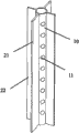
Fig. 1 is the structural representation of anti-seepage joint of underground continuous walls device of the present invention;
Fig. 2 is the sectional view of Fig. 1;
Fig. 3 is the structural representation of center steel pipe.
The specific embodiment
Embodiment 1
A kind of anti-seepage joint of underground continuous walls device is made up of a vertical center steel pipe 10 and four wing steel plates 20, and four wing steel plates 20 vertically are welded on center steel pipe 10 outer walls across.Said wing steel plate 20 is a rectangular slab, its long limit and 10 welding of center steel pipe, and should equate with pipe range on long limit.Four wing steel plates 20 radially extend all center line through center steel pipe 10.Wing steel plate 20 comprises a pair of long wing steel plate 21 and a pair of short limb steel plate 22, and what the minor face of wing steel plate was long is long wing steel plate 21, and what minor face was short is short limb steel plate 22, and long and short wing steel plate 21,22 is provided with at interval.Be equipped with injected hole 11 on the center steel pipe 10 between adjacent two wing steel plates 20, injected hole is evenly distributed on whole piece center steel pipe 10.
The form of construction work of above-mentioned anti-seepage joint of underground continuous walls device is following:
1. carry out the construction of a segment unit wall earlier, when putting into reinforcing cage, put into above-mentioned piecing devices, and in the steel pipe of center, put into high-pressure gasbag, gas-flow closure is lived injected hole, builds concrete and makes a long wing steel plate of piecing devices be fixed in this segment unit within the walls;
2. carry out the construction of next adjacent segment unit wall; The pressure that keeps high-pressure gasbag during this time after the concrete of treating body of wall is built, removes air bag; Slip casting in the steel pipe port of center; Slurry gets in the wall seam through injected hole, makes the gap sealing of two sections diaphragm wall junctions, reaches the purpose that prevents the artesian water infiltration.
Claims (6)
1. anti-seepage joint of underground continuous walls device; It is characterized in that be made up of a vertical center steel pipe and four wing steel plates, said four wing steel plates vertically are welded on the outer wall of steel pipe of center; Across is equipped with injected hole on the center steel pipe between said adjacent two wing steel plates.
2. device according to claim 1 is characterized in that, said wing steel plate is a rectangular slab, its long limit and the welding of center steel pipe.
3. device according to claim 2 is characterized in that, the long limit of said wing steel plate equates with pipe range.
4. device according to claim 3 is characterized in that, said four wing steel plates radially extend all center line through the center steel pipe.
5. according to claim 2 or 3 or 4 described devices, it is characterized in that said wing steel plate is divided into long and short wing steel plate, what the minor face of wing steel plate was long is long wing steel plate, and short is the short limb steel plate, and it is a pair of that said long and short wing steel plate respectively has, and be provided with at interval.
6. device according to claim 5 is characterized in that, said injected hole is evenly distributed on the steel pipe of whole piece center.
Priority Applications (1)
| Application Number | Priority Date | Filing Date | Title |
|---|---|---|---|
| CN201120196854U CN202131618U (en) | 2011-06-13 | 2011-06-13 | Seepage-prevention joint device for underground diaphragm wall |
Applications Claiming Priority (1)
| Application Number | Priority Date | Filing Date | Title |
|---|---|---|---|
| CN201120196854U CN202131618U (en) | 2011-06-13 | 2011-06-13 | Seepage-prevention joint device for underground diaphragm wall |
Publications (1)
| Publication Number | Publication Date |
|---|---|
| CN202131618U true CN202131618U (en) | 2012-02-01 |
Family
ID=45520391
Family Applications (1)
| Application Number | Title | Priority Date | Filing Date |
|---|---|---|---|
| CN201120196854U Expired - Fee Related CN202131618U (en) | 2011-06-13 | 2011-06-13 | Seepage-prevention joint device for underground diaphragm wall |
Country Status (1)
| Country | Link |
|---|---|
| CN (1) | CN202131618U (en) |
Cited By (5)
| Publication number | Priority date | Publication date | Assignee | Title |
|---|---|---|---|---|
| CN102296637A (en) * | 2011-06-13 | 2011-12-28 | 华南理工大学 | Seepage-proofing joint device of diaphragm wall |
| CN102733425A (en) * | 2012-07-25 | 2012-10-17 | 江苏华东地质建设集团有限公司 | Metal sheet pile joint for underground diaphragm walls and construction method for metal sheet pile joint |
| CN106759522A (en) * | 2017-02-04 | 2017-05-31 | 长江勘测规划设计研究有限责任公司 | A kind of the ground-connecting-wall G type joints and method of pre-buried repeatable Grouting Pipe |
| CN109339031A (en) * | 2018-11-20 | 2019-02-15 | 南昌工程学院 | A kind of buried concrete continuous wall connector percolator |
| CN110306533A (en) * | 2019-07-05 | 2019-10-08 | 广州穗岩土木科技股份有限公司 | The construction method of steel reinforced concrete column type connector and the joint continuous concrete wall |
-
2011
- 2011-06-13 CN CN201120196854U patent/CN202131618U/en not_active Expired - Fee Related
Cited By (6)
| Publication number | Priority date | Publication date | Assignee | Title |
|---|---|---|---|---|
| CN102296637A (en) * | 2011-06-13 | 2011-12-28 | 华南理工大学 | Seepage-proofing joint device of diaphragm wall |
| CN102733425A (en) * | 2012-07-25 | 2012-10-17 | 江苏华东地质建设集团有限公司 | Metal sheet pile joint for underground diaphragm walls and construction method for metal sheet pile joint |
| CN106759522A (en) * | 2017-02-04 | 2017-05-31 | 长江勘测规划设计研究有限责任公司 | A kind of the ground-connecting-wall G type joints and method of pre-buried repeatable Grouting Pipe |
| CN109339031A (en) * | 2018-11-20 | 2019-02-15 | 南昌工程学院 | A kind of buried concrete continuous wall connector percolator |
| CN109339031B (en) * | 2018-11-20 | 2020-10-20 | 南昌工程学院 | Underground concrete continuous wall connects anti-seepage device |
| CN110306533A (en) * | 2019-07-05 | 2019-10-08 | 广州穗岩土木科技股份有限公司 | The construction method of steel reinforced concrete column type connector and the joint continuous concrete wall |
Similar Documents
| Publication | Publication Date | Title |
|---|---|---|
| CN202131618U (en) | Seepage-prevention joint device for underground diaphragm wall | |
| CN103526766A (en) | Method for plugging relief well of deep foundation pit | |
| CN103321255A (en) | Underground concrete structural engineering joint waterproof construction method | |
| CN107268688A (en) | I-shaped steel joint of diaphragm wall reinforces the construction method of sealing | |
| CN204475311U (en) | The occlusion structure of box-shaped steel plate occlusion diaphragm wall | |
| CN203701436U (en) | Lap joint structure of vertical reinforcements and steel sleeve of assembled wall | |
| CN103741723A (en) | Joint waterproof structure of underground diaphragm wall of underground substation | |
| CN104674817B (en) | The method of the sealing of falling pressure type slip casting closure reserving hole | |
| CN203175569U (en) | Steel tube piece tunnel portal water-proof sealing structure in shield-driven tunnel breakthrough | |
| CN102444144A (en) | Device preventing concrete from streaming for I-shaped steel joint of diaphragm wall | |
| CN203639952U (en) | Underground diaphragm wall joint waterproof structure of underground substation | |
| CN203866777U (en) | Grouting treatment structure used after water stopping of cross joints of concrete dam fails | |
| CN203334285U (en) | Underground concrete structure engineering seam waterproof preparation grouting system | |
| CN203440820U (en) | Improved pouring pile end post-grouting device | |
| CN204199324U (en) | Connecting reinforcement cage i iron in construction of diaphragm wall | |
| CN202208932U (en) | Well shutting sleeve of dewatering well | |
| CN204941551U (en) | A kind of subway station of Curve Pipe Jacking supporting and protection structure enlarging shield-tunneling construction | |
| CN102296637A (en) | Seepage-proofing joint device of diaphragm wall | |
| CN203452101U (en) | Sealing device for post-pouring belt of external wall of multi-storey basement | |
| CN202970614U (en) | Water burst drilling and water sealing device | |
| CN202830881U (en) | Anti-seepage structure for joint of earth-rock dam and other buildings | |
| CN102296617A (en) | Post-grouting reinforcement construction method of flexible joints of diaphragm walls | |
| CN104141286A (en) | Construction adit blocking structure | |
| CN204510223U (en) | The two-way Grouting Pipe of vacuum-pumping | |
| CN203113349U (en) | Foundation trench shoring lattice type end structure |
Legal Events
| Date | Code | Title | Description |
|---|---|---|---|
| C14 | Grant of patent or utility model | ||
| GR01 | Patent grant | ||
| CF01 | Termination of patent right due to non-payment of annual fee |
Granted publication date: 20120201 Termination date: 20140613 |
|
| EXPY | Termination of patent right or utility model |