CN202111716U - Power over ethernet device and power over ethernet network - Google Patents
Power over ethernet device and power over ethernet network Download PDFInfo
- Publication number
- CN202111716U CN202111716U CN2010206221876U CN201020622187U CN202111716U CN 202111716 U CN202111716 U CN 202111716U CN 2010206221876 U CN2010206221876 U CN 2010206221876U CN 201020622187 U CN201020622187 U CN 201020622187U CN 202111716 U CN202111716 U CN 202111716U
- Authority
- CN
- China
- Prior art keywords
- module
- power supply
- power
- poe
- pin
- Prior art date
- Legal status (The legal status is an assumption and is not a legal conclusion. Google has not performed a legal analysis and makes no representation as to the accuracy of the status listed.)
- Expired - Fee Related
Links
Images
Abstract
The utility model discloses a power over ethernet device and a power over ethernet network. The power over ethernet device comprises a built-in power supply module, a switch master control module, a power supply transition module and an RJ 45 interface module. The power supply transition module is connected with the built-in power supply module and the switch master control module. External connecting 220V alternate current input is converted into direct current output by the built-in power supply module, and power is supplied for the switch master control module by the power supply transition module. The switch master control module is connected with the RJ 45 interface module, and is used for transmitting data signals to the RJ 45 interface module. The power supply transition module is connected with the RJ 45 interface module, and is used for providing power to the RJ 45 interface module. More than one power over ethernet device are cascaded to form the power over ethernet network. The power over ethernet device and the power over ethernet network enable the design of a power supply circuit to be simplified, allow a POE network power supply function to be realized while a switch power supply mode is enriched, and also enable the elastic scope of external connecting power input to be enlarged.
Description
Technical field
The utility model relates to a kind of POE device, especially relates to a kind of electric supply installation that is applied to equipment such as computer communication POE device such as switch.
Background technology
POE (Power Over Ethernet; POE) refers in existing Ethernet category 5 twisted pair (Cat.5) wiring architecture and do not do under the situation what changes; When being some network-termination device transmission of data signals, kind equipment provides the technology of direct current supply for this reason.The POE technology can guarantee the normal operation of existing network when guaranteeing existing structure wiring safety; A complete POE system comprises feeder ear equipment (PSE; Power Sourcing Equipment) and receiving end equipment (PD, Power Device) two parts.PSE equipment is the equipment for the ethernet client power devices, also is the manager of whole POE POE process simultaneously.And PD equipment is the PSE load of accepting power supply; It is the client device of POE system; Like IP phone, network security video camera; And many other ethernet devices such as palmtop PC (PDA) or charger for mobile phone (in fact, any power equipment of being no more than 13W can obtain corresponding electric power from the RJ45 socket).
Ethernet category 5 twisted pair wiring rules of the prior art is: 1,2,3, No. 6 pin transmission data, 4,5,7, No. 8 pin is vacant.Wherein, No. 1 pin is anodal for sending, and No. 2 pin are for sending negative pole, and No. 3 pin is anodal for receiving, and No. 6 pin are for receiving negative pole.In the prior art; The supply power mode of POE device only can satisfy the external 48V rectifier power source direct current input of usual manner; This exists the shortcoming of following aspects: 1, POE device receiving voltage scope is too narrow, is not easy to the selection of client to power supply adaptor; 2, POE device output current is little, and Maximum Power Output has only 13W, and the big slightly Ethernet switch equipment of power can't be used; 3, the existing Ethernet switch device is a simple power receiving equipment in whole network, does not possess the power supply capacity to subordinate's switch.
The utility model content
The utility model provides a kind of POE device and POE network; This utility model can overcome the simple supply power mode that only can satisfy the input of 48V direct current that prior art exists well; POE device and POE network receiving voltage scope are too narrow, can not satisfy the technical problem that the user selects multiple power adaptation mode.
The utility model provides a kind of embodiment of POE device; A kind of POE device; Comprise built-in power module, switch main control module, power transfer module and RJ45 interface module, the built-in power module links to each other with power transfer module, and power transfer module links to each other with the switch main control module; The built-in power module exchanges input with external 220V and converts direct current output to; Be the power supply of switch main control module through the power transfer module output current again, the switch main control module links to each other with the RJ45 interface module, and the switch main control module is to RJ45 interface module transmission of data signals; Power transfer module links to each other with the RJ45 interface module, and power transfer module provides power supply for the RJ45 interface module.
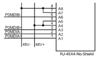
As the further execution mode of the utility model POE device, the RJ45 interface module is common Ethernet interface, and the RJ45 interface module comprises 8 leg, and wherein, 1,2,3,6 pin link to each other with the switch main control module, are used for transmission of data signals; 4 pin link to each other with power transfer module with 5 pin, are used to transmit positive 48V power supply, and 7 pin link to each other with power transfer module with 8 pin, are used to transmit negative 48V power supply.
As the further execution mode of the utility model POE device; The POE device comprises the external power supply socket; The external power supply socket links to each other with power transfer module; The external power supply socket is given the power supply of switch main control module by the power transfer module output current again through directly inserting the 48V direct current.
As the further execution mode of the utility model POE device, 4 pin of the Ethernet interface of RJ45 interface module link to each other with 5 pin, and 7 pin link to each other with 8 pin.
As the further execution mode of the utility model POE device, the external supply district of external power supply socket is direct current 7V-60V.
The utility model also provides a kind of embodiment of utilizing the POE device to be combined into the POE network; A kind of POE network; Comprise at least 2 POE devices, wherein, at least one POE device is as feeder ear equipment; At least one POE device is as receiving end equipment; Feeder ear equipment and receiving end equipment are supplied power through the netting twine cascade, can accept the electric current as the POE device output of feeder ear equipment automatically as the RJ45 interface module of the POE device of receiving end equipment, to realize power supply.
As the further execution mode of the utility model POE network; As the POE device of feeder ear equipment be connected the netting twine transmitting data information as the POE device of receiving end equipment 1,2,3,6 pin through Ethernet interface, 4 pin through Ethernet interface are connected netting twine and transmit positive 48V power supply with 5 pin; As the POE device of feeder ear equipment be connected the negative 48V power supply of netting twine transmission with 8 pin as the POE device of receiving end equipment 7 pin through Ethernet interface.
As the further execution mode of the utility model POE network, as the POE device of receiving end equipment simultaneously as feeder ear equipment.
Through using the described a kind of POE device of the utility model execution mode,, realize the POE network power supply function through simplification innovative design to power supply lines.Flexible and changeable in the POE network, both can be that PSE (power supply) equipment also can be PD (receiving) equipment, simplify the complexity of using.Integrated external alternating current 220V input, integrated external power supply power supply port can be supported the ultra wide direct voltage input of 7~60V, increases elasticity, and is user-friendly.
Description of drawings
In order to be illustrated more clearly in the utility model embodiment or technical scheme of the prior art; To do to introduce simply to the accompanying drawing of required use in embodiment or the description of the Prior Art below; Obviously, the accompanying drawing in describing below only is some embodiment of the utility model, for those of ordinary skills; Under the prerequisite of not paying creative work, can also obtain other accompanying drawing according to these accompanying drawings.
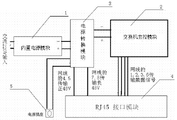
Fig. 1 is the structure composition frame chart of a kind of POE device of the utility model;
Fig. 2 is the wiring schematic diagram of a kind of POE device of the utility model;
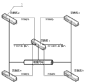
Fig. 3 is the wiring schematic diagram that 16 oral sexes are changed planes that is applied to of a kind of POE device of the utility model;
Fig. 4 is the single port power supply the principle figure of a kind of POE device of the utility model;
Fig. 5 is the circuit theory diagrams of a kind of POE device of the utility model power transfer module;
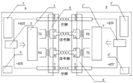
Fig. 6 is the application architecture figure of a kind of POE device of the utility model;
Wherein: 1,1 '-the built-in power module, 2,2 '-the switch main control module, 3,3 '-power transfer module,
4,4 '-the RJ45 interface module, 5,5 '-the external power supply socket, 6-power conversion chip, 7-POE device.
Embodiment
To combine the accompanying drawing among the utility model embodiment below, the technical scheme among the utility model embodiment is carried out clear, intactly description, obviously, described embodiment only is a part of embodiment of the utility model, rather than whole embodiment.Based on the embodiment in the utility model, those of ordinary skills are not making the every other embodiment that is obtained under the creative work prerequisite, all belong to the scope of the utility model protection.
Embodiment as a kind of POE device of the utility model; The POE device comprises built-in power module 1, switch main control module 2, power transfer module 3 and RJ45 interface module 4, the power supply of built-in power module 1 main responsible switch main control module 2 and the power supply of POE network.The POE device is supported three kinds of supply power modes, shown in the structure composition frame chart of Fig. 1.
First kind of mode is that the built-in power module 1 through DC 48V output arrives power transfer module 3 again through external AC 220V input, gives the switch main control module 2 power supplies by power transfer module 3 output currents at last;
The second way is the external power supply socket 5 through external direct current, through the built-in power module 1 of DC 48V output, gives the switch main control module 2 power supplies by power transfer module 3 output currents;
The third mode is to carry out the POE power supply through the RJ45 interface module 4 of switch.
When the POE device changeed built-in power module 1 or supply socket 5 power supplies of direct current 48V output through alternating current 220V, exchange opportunity started the PSE function automatically, gives POE network output current.In being operated in POE PSE network, the POE device can automatically operate in the PD pattern, accepts the electric current of POE network from 4,5,7,8 pin of RJ45 interface module 4 and supplies power to self.When switch main control module 2 obtains operating voltage; Switch main control module 2 can carry out self check; After passing through, self check can detect the port of all RJ45 interface modules 4; When port one, 2,3, when 6 pin have transfer of data, switch main control module 2 is understood according to setting up interim switching path between the originator of Frame and the target receiver, accomplishes the exchanges data work between the port.
When the power excess load of built-in power module 1, external 48V power supply undercompensation can be provided, also can use external power supply separately.The built-in power power supply can be do not used, externally external 9V/1A AC power supplies power supply can be do not used under the electric power thus supplied at switch.Also can not use under the built-in power situation, use external power supply to give switch and subordinate's power supply for exchange.
As shown in Figure 1, the POE device is supported 3 kinds of supply power modes:
The user can realize that alternating current 220V changes direct current 48V output through built-in power module 1, gives the power supply of Ethernet electric supply installation and starts the POE network power supply function.
Can directly import direct current 48V from external power supply socket 5 and give the power supply of Ethernet electric supply installation, and start the POE network power supply function, when being operated in general mode, the external power supply socket is supported the supply district of 7V-60V.
In POE PSE network, the electric current that the RJ45 interface module 4 of POE device can be accepted the output of PSE equipment automatically comes to power supply for exchange.
As shown in Figure 2; After giving the A power devices through the direct current jack of built-in power module 1 or external power supply socket 5, when B equipment was connected with A equipment, electric current can be given the A power devices through 4,5,7,8 pin of netting twine; 1,2,3,6 pin transmission of data signals communicate with A equipment simultaneously.B equipment also correspondingly comprise built-in power module 1 ', switch main control module 2 ', power transfer module 3 ', RJ45 interface module 4 ', external power supply socket 5 '.Otherwise when giving the B power devices through the direct current jack of built-in power module 1 or external power supply socket 5, B equipment also can be given A power devices and intercommunication mutually through netting twine.
As Fig. 3 and shown in Figure 4 be that the POE device is applied to the winding diagram on 16 port switch, 16 RJ45 interface modules altogether of U1, U2, U3, four group of four port of U5 are arranged among the figure, each RJ45 interface module has 8 terminals.With 4 pin and the series connection of 5 pin of all RJ45 interface modules is a network; 7 pin of all RJ45 interface modules and the series connection of 8 pin are a network; 4 pin of RJ45 interface module and 5 pin are connected and are transmitted positive voltage, 7 pin of RJ45 interface module and the 8 pin transmission negative voltage that is together in series.
As shown in Figure 5 is the circuit theory diagrams of power transfer module, connects by mode of connection shown in Figure 2 16 ports with switch earlier, realizes the POE power supply through the power conversion chip 6 of power transfer module 3 again.When the POE device is PSE (power supply unit); Supply with built-in power module 1 by outside 80V-240V; Output DC 48V voltage; The rectifier bridge of leading up to becomes 3.3V to supply with that switch device uses to the power conversion chip 6 of power transfer module 3 through internal conversion, and each port that another road directly is given among Fig. 2 does not have on the idle pin of transfer of data.
As shown in Figure 6 is the application architecture figure that forms the POE network through the mutual cascade of POE device, and the POE network shown in the figure comprises switch 1, switch 2, switch 3, switch 4,5 five POE devices of switch.Wherein, sketch map that POE device switch 1 is supplied power to four switches 2 as the POE device of receiving end equipment, switch 3, switch 4, switch 5 respectively as feeder ear equipment.When using external AC (interchange) input, convert 48V DC to through built-in power module 1 and supply power to power receiving equipment, the while converts the power supply of 3.3V confession switch device self to through the power conversion chip 6 of power transfer module 3 again; Also can directly import direct current 48V and give the power supply of Ethernet electric supply installation through power transfer module 3 from external power supply socket 5; When not having the external AC input; This POE device is through the mutual cascade of netting twine; The netting twine power taking can be passed through, the voltage of DC (direct current) 7V-60V from feeder ear can be accepted this moment as the POE device of power receiving equipment.Each can be simultaneously as feeder ear POE device as the POE device of receiving end equipment.
The above only is the preferred implementation of the utility model; Should be pointed out that for those skilled in the art, under the prerequisite that does not break away from the utility model principle; Can also make some improvement and retouching, these improvement and retouching also should be regarded as the protection range of the utility model.
Claims (8)
1. POE device; It is characterized in that: comprise built-in power module (1), switch main control module (2), power transfer module (3) and RJ45 interface module (4); Built-in power module (1) links to each other with power transfer module (3); Power transfer module (3) links to each other with switch main control module (2), and built-in power module (1) exchanges input with external 220V and converts direct current output to, is switch main control module (2) power supply through power transfer module (3) output current again; Switch main control module (2) links to each other with RJ45 interface module (4); Switch main control module (2) is to RJ45 interface module (4) transmission of data signals, and power transfer module (3) links to each other with RJ45 interface module (4), and power transfer module (3) provides power supply for RJ45 interface module (4).
2. a kind of POE device according to claim 1; It is characterized in that: described RJ45 interface module (4) is common Ethernet interface; RJ45 interface module (4) comprises 8 leg; Wherein, 1,2,3,6 pin link to each other with switch main control module (2), are used for transmission of data signals; 4 pin link to each other with power transfer module (3) with 5 pin, are used to transmit positive 48V power supply, and 7 pin link to each other with power transfer module (3) with 8 pin, are used to transmit negative 48V power supply.
3. a kind of POE device according to claim 1 and 2; It is characterized in that: described POE device comprises external power supply socket (5); External power supply socket (5) links to each other with power transfer module (3); External power supply socket (5) is given switch main control module (2) power supply by power transfer module (3) output current again through directly inserting the 48V direct current.
4. a kind of POE device according to claim 3 is characterized in that: 4 pin of the Ethernet interface of said RJ45 interface module (4) link to each other with 5 pin, and 7 pin link to each other with 8 pin.
5. a kind of POE device according to claim 3 is characterized in that: the external supply district of said external power supply socket (5) is direct current 7V-60V.
6. POE network that utilizes the described POE device of claim 1 to be combined into; It is characterized in that: comprise at least 2 POE devices (7); Wherein, At least one POE device is as feeder ear equipment, and at least one POE device is as receiving end equipment, and feeder ear equipment and receiving end equipment are supplied power through the netting twine cascade; Can accept electric current automatically as the RJ45 interface module (4) of the POE device of receiving end equipment, to realize power supply as the POE device output of feeder ear equipment.
7. a kind of POE network according to claim 6; It is characterized in that: as the POE device of feeder ear equipment be connected the netting twine transmitting data information as the POE device of receiving end equipment 1,2,3,6 pin through Ethernet interface, 4 pin through Ethernet interface are connected netting twine and transmit positive 48V power supply with 5 pin; As the POE device of feeder ear equipment be connected the negative 48V power supply of netting twine transmission with 8 pin as the POE device of receiving end equipment 7 pin through Ethernet interface.
8. according to claim 6 or 7 described a kind of POE devices, it is characterized in that: described POE device as receiving end equipment is simultaneously as feeder ear equipment.
Priority Applications (1)
| Application Number | Priority Date | Filing Date | Title |
|---|---|---|---|
| CN2010206221876U CN202111716U (en) | 2010-11-24 | 2010-11-24 | Power over ethernet device and power over ethernet network |
Applications Claiming Priority (1)
| Application Number | Priority Date | Filing Date | Title |
|---|---|---|---|
| CN2010206221876U CN202111716U (en) | 2010-11-24 | 2010-11-24 | Power over ethernet device and power over ethernet network |
Publications (1)
| Publication Number | Publication Date |
|---|---|
| CN202111716U true CN202111716U (en) | 2012-01-11 |
Family
ID=45437167
Family Applications (1)
| Application Number | Title | Priority Date | Filing Date |
|---|---|---|---|
| CN2010206221876U Expired - Fee Related CN202111716U (en) | 2010-11-24 | 2010-11-24 | Power over ethernet device and power over ethernet network |
Country Status (1)
| Country | Link |
|---|---|
| CN (1) | CN202111716U (en) |
Cited By (4)
| Publication number | Priority date | Publication date | Assignee | Title |
|---|---|---|---|---|
| CN103152183A (en) * | 2013-01-30 | 2013-06-12 | 国光电器股份有限公司 | Electric modem switching device and method for mutual switching of electric signals and network signals |
| CN105515560A (en) * | 2016-01-27 | 2016-04-20 | 灿芯半导体(上海)有限公司 | Voltage conversion circuit |
| CN105515559A (en) * | 2016-01-26 | 2016-04-20 | 深圳市共进电子股份有限公司 | Voltage switching circuit applied to PSE switch |
| CN106330468A (en) * | 2016-08-23 | 2017-01-11 | 锐捷网络股份有限公司 | Ethernet power supply device and Ethernet power supply method |
-
2010
- 2010-11-24 CN CN2010206221876U patent/CN202111716U/en not_active Expired - Fee Related
Cited By (6)
| Publication number | Priority date | Publication date | Assignee | Title |
|---|---|---|---|---|
| CN103152183A (en) * | 2013-01-30 | 2013-06-12 | 国光电器股份有限公司 | Electric modem switching device and method for mutual switching of electric signals and network signals |
| CN105515559A (en) * | 2016-01-26 | 2016-04-20 | 深圳市共进电子股份有限公司 | Voltage switching circuit applied to PSE switch |
| CN105515559B (en) * | 2016-01-26 | 2018-09-14 | 深圳市共进电子股份有限公司 | A kind of voltage commutation circuit applied to PSE interchangers |
| CN105515560A (en) * | 2016-01-27 | 2016-04-20 | 灿芯半导体(上海)有限公司 | Voltage conversion circuit |
| CN106330468A (en) * | 2016-08-23 | 2017-01-11 | 锐捷网络股份有限公司 | Ethernet power supply device and Ethernet power supply method |
| CN106330468B (en) * | 2016-08-23 | 2019-08-20 | 锐捷网络股份有限公司 | A kind of Power over Ethernet device and Power over Ethernet method |
Similar Documents
| Publication | Publication Date | Title |
|---|---|---|
| CN102025510A (en) | Ethernet power supply unit and network | |
| TWI388153B (en) | Network equipment | |
| CN102761422B (en) | A kind of power over ethernet electric power system of cascade and Power over Ethernet method thereof | |
| CN101436883A (en) | Electric power modem | |
| CN101409626B (en) | Optical network unit and method for controlling power supply user terminal access thereof | |
| CN202111716U (en) | Power over ethernet device and power over ethernet network | |
| CN102404125A (en) | Power supply method and system of Ethernet | |
| CN203466837U (en) | Network camera power supply device | |
| CN110289972A (en) | A kind of network equipment and network system based on Ethernet | |
| CN102710425B (en) | Ethernet power relay system, feeder device and access bridging device | |
| CN207020661U (en) | One kind communication multiplex circuit | |
| CN205754408U (en) | A kind of switch with forward and reverse function of supplying power | |
| CN101753319B (en) | Network equipment | |
| CN203219325U (en) | Intelligent PoE (power over Ethernet) switch | |
| CN211352210U (en) | Ethernet power supply signal amplification and signal extender of POE technology | |
| CN107360005A (en) | A kind of receiving end equipment and by method for electrically | |
| CN202817700U (en) | Power receiving conversion circuit based on power provided by ethernet | |
| CN201156230Y (en) | Notebook computer based on PoE technology | |
| CN205490591U (en) | Network switching system with POE power adaption function | |
| CN109728916A (en) | A kind of Power over Ethernet single port extender of POE technology | |
| CN209250636U (en) | Power supply ethernet network based on power line Ethernet merges adaptive device | |
| CN102866761A (en) | Intelligent computer system for concentrated power supply with twisted pair cable | |
| CN109743080A (en) | Power supply ethernet network fusion adaptive device and its method based on power line Ethernet | |
| CN201127103Y (en) | Double-light-mouth switch module | |
| CN209088978U (en) | A kind of power supply photoelectric conversion device of more power output interfaces |
Legal Events
| Date | Code | Title | Description |
|---|---|---|---|
| C14 | Grant of patent or utility model | ||
| GR01 | Patent grant | ||
| CF01 | Termination of patent right due to non-payment of annual fee |
Granted publication date: 20120111 Termination date: 20141124 |
|
| EXPY | Termination of patent right or utility model |