CN202108089U - Water-free type trap - Google Patents
Water-free type trap Download PDFInfo
- Publication number
- CN202108089U CN202108089U CN2011200395722U CN201120039572U CN202108089U CN 202108089 U CN202108089 U CN 202108089U CN 2011200395722 U CN2011200395722 U CN 2011200395722U CN 201120039572 U CN201120039572 U CN 201120039572U CN 202108089 U CN202108089 U CN 202108089U
- Authority
- CN
- China
- Prior art keywords
- pipe portion
- trap
- fluid
- elastic component
- housing
- Prior art date
- Legal status (The legal status is an assumption and is not a legal conclusion. Google has not performed a legal analysis and makes no representation as to the accuracy of the status listed.)
- Expired - Fee Related
Links
Images


Abstract
The scheme provides a water-free type trap which is arranged on a pipeline for circulation liquid, is used for preventing waste gas, mosquitoes and the like from reversely invading into rooms and other spaces through the trap, and is provided with a shell. The shell is internally provided with at least one elastic piece which is sleeve-shaped, and is provided with an opening at one end and an opening/closing structure at the other end; when a fluid flows at the inner side of the elastic piece, the opening/closing end of the elastic piece is opened for the fluid to pass, and after the fluid passes, the opening/closing end of the elastic piece is closed automatically. By adopting the structure, the trap can naturally seal a reverse passageway of the pipeline without being provided with water seal for water accumulation.
Description
Technical field
This case is the structure of relevant trap, refers to that especially a kind of water liquid of exempting from can prevent that waste gas, mosquito etc. from exempting from the ability of swimming trap through space such as the reverse intrusion of trap is indoor.
Background technology
General sanitary installation; The gutter that comprises flush toilet, wash basin etc. all is provided with the structure of trap, mainly is preventing the reverse discharge pipe line that sees through sanitary apparatus such as waste gas, foul smell, germ, mosquito; Intrude into indoorly, make indoor antihygienic environment that becomes.
This known trap; It mainly is the design that utilizes bends such as special U type of trap or P type or turnover; Let the dirty waste water that flows through sanitary installation produce ponding at bend or turning point; Form about 50mm-100mm water seal (effectively water seal depth), the ponding pipelines on two sides is separated by the ponding sealing, thereby prevent the reverse invasions such as foul smell, mosquito of the curved rear side of ponding.Only, this traditional trap roughly has following disappearance:
1.) siphonage: the siphonage that this kind trap is produced because of adjacent sanitary installation draining easily; Water in the trap drawn gradually siphon away; Make depth of accumulated water not enough, cause the phenomenon of " broken envelope " (effective depth of water seal is not enough, and causes water seal to be lost efficacy).
2.) Evaporation Phenomenon: the water seal of the trap of the sanitary installation that seldom uses can produce the phenomenon of " broken envelope " gradually because Evaporation Phenomenon causes depth of accumulated water not enough.
3.) trap usually because foreign matter is piled up deposition and blocked the tortuous water seal of structure gradually, can cause current to have some setbacks even blocks, though partly the bottom of trap is provided with the design of getting rid of dirt, needs cleaning at any time, and this situation can cause user's puzzlement.
Like TaiWan, China patent M338939 number, it is a kind of structure-improved of V-type double-purpose trap, can reduce the device space and can not use special tool can will clean the creation that flap is locked or opened simply fast and positively; But this patent case still is difficult for avoiding for above-mentioned three kinds of alleged disappearances.The and for example improvement of No. 216083 trap of letters patent has the bend pipe of a bifurcated, and bend pipe forms an apotheca in the bending place; And the bottom of apotheca is to extending below a body; Have internal thread in the body, for the externally threaded capping of screw lock one tool, and the internal thread of body and this apotheca joint ring are established a flange; And the external screw thread top of capping ring is established an embedding portion; For being embedded a waterproof case, make waterproof case push against the flange bottom in body, with the external screw thread of the internal thread of closed tube and the capping place that is spirally connected each other.It is the disappearance of water seal to store ponding that above-mentioned patent also exists tradition.
Case by above-mentioned two domestic patents can know, makes the main body of water seal with water liquid, and big city produces the disappearance of aforementioned conventional trap.
Application artificially improves these disappearances, and lappingout has been created this case with great concentration.
Summary of the invention
The main purpose of this case is the trap of water seal in that a kind of water liquid that needn't make is provided; Has a housing with the serial connection fluid line; One able to turn on or off passage is set in housing; But this passage exhaust fluid (below alleged fluid comprise liquid such as water liquid and be in the various materials in the liquid), when not circulating, this case trap can form closure state automatically; And when it was in reverse pressure, the passage that can open/close still was closed state, to prevent the side in addition of waste gas, foul smell, germ, the reverse entering trap of mosquito.
The able to turn on or off passage that this case is alleged; Create an elastic component, utilize the gravity of the materials such as fluid of circulation, the closed originally position of pushing open of nature forms opening; Smoothly fluids such as dirty waste water are emitted; Finish when fluid roughly discharges, this elastic component promptly automatically replies into closure state, to block the invasion of foul smell, mosquito etc.
The elastic component that this case is alleged; Process by soft material; It is optional to be cannula-like freely by type material such as rubber, polyurethane, polyvinyl chloride or silica gel or its combination, and having a side is to accept the opening that fluid passes through; Opposite side then be at ordinary times the sealing opening, this be opened on fluid through the time can open automatically.
This case can be further at a plurality of elastic components of enclosure interior device, to reach the demand of the reverse circulation of closed conduct more.
Time purpose of this case makes this case be arranged at the pipeline of circulated gases, and this opened/remain silent to form and opens shape when wherein the inside of elastic component received forward pressure, and this opened/remain silent still sealing when the outside of elastic component received reverse pressure.
A kind of ability of swimming trap of exempting from; Be installed in the fluid flow pipeline; Comprise: a housing: be hollow tubular body, have the first pipe portion, the second pipe portion and the 3rd pipe portion that link to each other in order, wherein the circulation duct efferent is accepted by the first pipe portion; The second pipe portion inside provides the setting of elastic component, the 3rd pipe portion continued access circulation duct; At least one said elastic component: be arranged at enclosure interior; Be hollow tubular, have the entrance point, body and the port of export that link to each other in order; Entrance point is accepted fluid, and to get into elastic component inner, and body can be out of shape or expand, the port of export at fluid through out-of-date unlatching, fluid through after automatically reply and be closure.
The useful technique effect that the utility model reaches is:
1. whole appearance is smooth and easy, and the sinuate sealing structure for water of tool is not very easily got rid of by current and opened/obstruction of closed end.
2. do not have the setting of sealing structure for water, can not cause because of effects such as siphon, evaporations " broken envelope " phenomenon produces the puzzlement of foul smell, the reverse invasion of mosquito.
3. this case trap very easily is set in the pipeline of fluid or gas.
Description of drawings
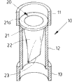
The embodiment stereogram of Fig. 1 this case trap (partly analysing and observe);
The front elevation drawing of the embodiment of Fig. 2 this case trap;
The top view of the embodiment of Fig. 3 this case trap;
Fig. 4 is an A-A hatching line view among Fig. 3;
Fig. 5 is a B-B hatching line view among Fig. 3;
Fig. 6 this case trap user mode embodiment (one);
Fig. 7 this case trap user mode embodiment (two);
Another embodiment of Fig. 8 this case trap;
Fig. 9 this case trap user mode embodiment (three);
Another embodiment (two) of Figure 10 this case trap.
Description of reference numerals
The 10-housing; The 11-first pipe portion; The 12-second pipe portion; 13-the 3rd pipe portion; 11a, 12a, 12b, 13a-thread; The 20-elastic component; The 21-entrance point; The 21a-ora terminalis; The 22-body; The 23-port of export; 20 ', 20 "-elastic component; First communicating pipe of 30-; Second communicating pipe of 40-; The 50-tank; The 60-fluid.
The specific embodiment
Shown in Fig. 1-5, be the example structure figure of this case trap, it comprises a housing 10 and at least one elastic component 20, this elastic component 20 is arranged in the housing 10.
Alleged housing 10, be device on the fluid flow pipeline, be hollow tubular body, a stable structure spare is provided; Its formation comprises in order the first pipe portion 11, the second pipe portion 12 and the 3rd pipe portion 13 that links to each other; Wherein (please with reference to Fig. 6,7) accepted for first communicating pipe 30 in the first pipe portion 11; The second pipe portion, 12 inside provide the setting of elastic component 20, the 3rd pipe portion second communicating pipe 40 of 13 continued accesses (please with reference to Fig. 6,7).
Alleged elastic component 20; Be arranged in the housing 10; The circulation of fluid is provided; By the hollow member that soft material (like rubber, silica gel etc.) is processed, its formation comprises in order an entrance point 21, hollow tube 22 and a port of export 23 (being alleged the opening of above stated specification/closed end) that links to each other, global shape by the opening of entrance point 21 gradually to the closure of the port of export 23; The ora terminalis 21a of this entrance point 21 can supply to be fixed in housing 10 inside; Entrance point 21 keeps openings, accept by first communicating pipes 30 fluid that flows down of inside get into the inner space that elastic component 20 defines, this body 22 can because of fluid pass through change shape or make hose expansion; The port of export 23 of connection is become by closure state have open state; When also promptly the inner space defined of this elastic component 20 is under pressure, the port of export 23 in no fluid through the time be closed form, fluid through the time then opened.
Above-mentioned alleged entrance point 21; It can be arranged in the housing 10 with the form fix with ora terminalis 21a shown in embodiment, its also otherwise be provided with; For example to paste, to press from both sides the fixing of various forms generals such as pulling, so that elastic component 20 is set in the housing 10.
The as above alleged port of export 23 is the hatch frame that can be unlocked, when its this opening when making with soft material is closure state; When body 22 inboards receive outside thrust; The opening of this port of export 23 is promptly opened by interlock, and opening slightly in a tubular form forms the negotiable open state of fluid.
Like Fig. 6, shown in 7, for this case is arranged at a tank 50 belows, with a kind of embodiment sketch map as trap.Tank 50 belows connect slotting the pulling in the first pipe portion 11 of housing 10 in 30, the first communicating pipes 30 of first communicating pipe below, and press from both sides the elastic component 20 of pulling, in the 3rd pipe portion 12 slotting the pulling for second communicating pipe 40 of housing 10; In first communicating pipe 30 and 11 in the first pipe portion, and second communicating pipe 40 and the 3rd pipe portion 12 all can silica gel etc. any form seal, in case leak.In Fig. 6, be shown as no fluid and pass through, then the port of export 23 of the elastic component 20 of trap is closure state, under this state, is difficult to reverse first communicating pipe 30 of entering by the gas in second communicating pipe 40, mosquito etc.What in Fig. 7, shown is to have fluid 60 to show example through the state of elastic component 20; Fluid 60 makes the body 22 of elastic component 20 produce distortion because of the inside of gravity factor by elastic component 20 outwards struts, and the port of export 23 is opened; After fluid 60 flows through; The factor that is strutted elastic component 20 by elastic component 20 inside disappears, and then the port of export 23 is an auto-closing, reverts back to state shown in Figure 6.
As shown in Figure 8, be another embodiment of this case, two elastic components 20 ', 20 are set " in housing 10, make the effect of reaching inverse closing better.
Be illustrated in figure 9 as another embodiment of this case creation, on the fluid passage that this case device one is oblique; When then fluid is flowed through elastic component 20 inside, elastic component 20 will make the port of export 23 of its below form openings because of the factors such as gravity of fluid, and fluid is circulated naturally, treat after the fluid flow, and the port of export 23 can the nature closure.
The whole trap of considering this case can be disassembled replacing or only change elastic component 20, and the first pipe portion 11 or the 3rd pipe portion 13 of this case housing 10 can be made into mobilizable structure; Shown in figure 10; Between the first pipe portion 11, the 3rd pipe portion 13 and the second pipe portion 12, thread 11a, 12a are set, 12b, 13a are because the first pipe portion 11 or the 3rd pipe portion 13 can move up and down in the second pipe portion 12 relatively; Even first pipe portion 11 or the 3rd pipe portion 13 break away from the second pipe portion 12; Then whole trap 10 can be disassembled, and it can be replaced, or only changes inner elastic component 20.It only is an embodiment that above-mentioned mode with spiral is dismantled trap, not limited thereto structure, and also promptly, the relevant structure that the dismounting of this case trap is done is provided with the equivalent manners of only this case, all should belong to the claim of this case.
Like the trap of above-mentioned this case, the maximum difference of itself and traditional trap is again in sealing structure for water needn't be set.This case thereby have following advantage:
1. whole appearance is smooth and easy, and the sinuate sealing structure for water of tool is not very easily got rid of by current and opened/obstruction of closed end.
2. do not have the setting of sealing structure for water, can not cause because of effects such as siphon, evaporations " broken envelope " phenomenon produces the puzzlement of foul smell, the reverse invasion of mosquito.
3. this case trap very easily is set in the pipeline of fluid or gas.
More than be illustrative to the description of the utility model; And it is nonrestrictive; Those skilled in the art is understood, and the spirit and the interior of scope that limit in claim can carry out many modifications, variation or equivalence to it, but they all will fall in the protection domain of the utility model.
Claims (6)
1. exempt from the ability of swimming trap for one kind, be installed in the fluid flow pipeline, it is characterized in that, comprising:
One housing: be hollow tubular body, have the first pipe portion, the second pipe portion and the 3rd pipe portion that link to each other in order, wherein the circulation duct efferent is accepted by the first pipe portion, and the second pipe portion inside provides the setting of elastic component, the 3rd pipe portion continued access circulation duct;
At least one said elastic component: be arranged at enclosure interior; Be hollow tubular, have the entrance point, body and the port of export that link to each other in order; Entrance point is accepted fluid, and to get into elastic component inner, and body can be out of shape or expand, the port of export at fluid through out-of-date unlatching, fluid through after automatically reply and be closure.
2. according to exempting from the ability of swimming trap shown in the claim 1, it is characterized in that the first pipe portion and the second pipe portion of alleged housing can relative motions.
3. according to exempting from the ability of swimming trap shown in the claim 1, it is characterized in that the first pipe portion and the second pipe portion of alleged housing can break away from.
4. according to exempting from the ability of swimming trap shown in the claim 1, it is characterized in that the 3rd pipe portion and the second pipe portion of alleged housing can relative motions.
5. according to exempting from the ability of swimming trap shown in the claim 1, it is characterized in that the 3rd pipe portion and the second pipe portion of alleged housing can break away from.
6. according to exempting from the ability of swimming trap shown in the claim 1, it is characterized in that alleged elastic component is processed by soft material.
Priority Applications (1)
| Application Number | Priority Date | Filing Date | Title |
|---|---|---|---|
| CN2011200395722U CN202108089U (en) | 2011-02-16 | 2011-02-16 | Water-free type trap |
Applications Claiming Priority (1)
| Application Number | Priority Date | Filing Date | Title |
|---|---|---|---|
| CN2011200395722U CN202108089U (en) | 2011-02-16 | 2011-02-16 | Water-free type trap |
Publications (1)
| Publication Number | Publication Date |
|---|---|
| CN202108089U true CN202108089U (en) | 2012-01-11 |
Family
ID=45433527
Family Applications (1)
| Application Number | Title | Priority Date | Filing Date |
|---|---|---|---|
| CN2011200395722U Expired - Fee Related CN202108089U (en) | 2011-02-16 | 2011-02-16 | Water-free type trap |
Country Status (1)
| Country | Link |
|---|---|
| CN (1) | CN202108089U (en) |
Cited By (5)
| Publication number | Priority date | Publication date | Assignee | Title |
|---|---|---|---|---|
| CN102561480A (en) * | 2012-02-16 | 2012-07-11 | 全球概念解决方案(澳大利亚)有限公司 | Separating device for drainage system |
| CN104153445A (en) * | 2014-08-04 | 2014-11-19 | 孙燕平 | Straight-discharging odorless water-saving toilet bowl |
| CN104818757A (en) * | 2015-05-08 | 2015-08-05 | 张昭 | Urine rinse-free type dual purpose toilet |
| CN106284543A (en) * | 2016-10-14 | 2017-01-04 | 贵州大学 | A kind of sliceable prolongation odor-resistant downcomer pipe |
| CN107386388A (en) * | 2017-07-24 | 2017-11-24 | 浙江伟星新型建材股份有限公司 | A kind of downcomer seal fitting and its special joint |
-
2011
- 2011-02-16 CN CN2011200395722U patent/CN202108089U/en not_active Expired - Fee Related
Cited By (6)
| Publication number | Priority date | Publication date | Assignee | Title |
|---|---|---|---|---|
| CN102561480A (en) * | 2012-02-16 | 2012-07-11 | 全球概念解决方案(澳大利亚)有限公司 | Separating device for drainage system |
| CN104153445A (en) * | 2014-08-04 | 2014-11-19 | 孙燕平 | Straight-discharging odorless water-saving toilet bowl |
| CN104818757A (en) * | 2015-05-08 | 2015-08-05 | 张昭 | Urine rinse-free type dual purpose toilet |
| CN106284543A (en) * | 2016-10-14 | 2017-01-04 | 贵州大学 | A kind of sliceable prolongation odor-resistant downcomer pipe |
| CN107386388A (en) * | 2017-07-24 | 2017-11-24 | 浙江伟星新型建材股份有限公司 | A kind of downcomer seal fitting and its special joint |
| CN107386388B (en) * | 2017-07-24 | 2019-12-24 | 浙江伟星新型建材股份有限公司 | Sewer pipe sealing fitting and special joint thereof |
Similar Documents
| Publication | Publication Date | Title |
|---|---|---|
| CN202108089U (en) | Water-free type trap | |
| US20170260725A1 (en) | Valve | |
| CN102720252A (en) | Same-layer drainage device with ultralow structure | |
| KR20120132024A (en) | Drain Traps | |
| WO2017120593A1 (en) | Mechanical valve for waterless urinal | |
| CN206418805U (en) | Building toilet and its drainage system | |
| CN202672325U (en) | Same floor drainage device with ultralow structure | |
| KR102489671B1 (en) | drain for integrated bent | |
| CN106121014B (en) | A kind of air self-returning formula Homofloor drainage system | |
| CN202214780U (en) | Drainage device | |
| KR20170110549A (en) | Cleaning unit for sewage and wastewater drain pipe cleaning and Cleaning method of sewage and wastewater drain pipe using the cleaning unit | |
| CN207846588U (en) | A kind of public restroom scale removal deodorization system | |
| CN208979064U (en) | A kind of Aluminium ships drain structure | |
| KR20180106024A (en) | Waste trap structure | |
| CN205314183U (en) | Deodorant elbow | |
| CN203546841U (en) | Multifunctional deodorant floor drain | |
| KR20130003088A (en) | Drain sewage having preventing function of bad smell | |
| CN2623753Y (en) | Multipurpose hygienic drainage floor drain for SARS prevention | |
| JP2003119859A (en) | Drain system and catch basin | |
| KR101181937B1 (en) | Piping connection structure of multiple trap | |
| CN204435533U (en) | A kind of three prevention floor drains | |
| CN216973672U (en) | Buoyancy ball floor drain | |
| JP2014119111A (en) | Lower vent valve for drainage | |
| KR102529793B1 (en) | Multi-unit that can prevent frequent inspection and sedimentation of dirt while connecting the sewage perpendicularity pipe installed in the apartment complex with the transverse main pipe and a method for preventing sedimentation at the connection between the sewer perpendicularity pipe and the transverse main pipe using the multi-unit | |
| CN214940729U (en) | Water collector with rear flat tubes |
Legal Events
| Date | Code | Title | Description |
|---|---|---|---|
| C14 | Grant of patent or utility model | ||
| GR01 | Patent grant | ||
| C17 | Cessation of patent right | ||
| CF01 | Termination of patent right due to non-payment of annual fee |
Granted publication date: 20120111 Termination date: 20140216 |