The special use that novel cable the does not have gum cover pipe processing plumber's dress of helping pull a cart
Technical field
The utility model relates to the plumber dress of helping pull a cart, particularly, and the special use that relates to novel cable and do not have the processing of the gum cover pipe plumber's dress of helping pull a cart.
Background technology
In the industry of whole making line formula sensor, all use aperture size to be through above the cable greater than the gum sleeve of cable outside dimension, with glue gum sleeve and cable are bonded together then.But because glue is chemical reagent, in the process that adopts glue that gum sleeve is fixed, glue has corrosivity to cable and gum sleeve, can accelerate the aging of cable and gum sleeve like this, influences the service life of product; The long-term glue that uses also influences the healthy of employee.
The utility model content
At defective of the prior art, the special use that the purpose of this utility model provides a kind of novel cable the does not have gum cover pipe processing plumber's dress of helping pull a cart.
According to an aspect of the present utility model, the special use that provides a kind of novel cable the not have gum cover pipe processing plumber's dress of helping pull a cart, comprise workbench, it is characterized in that, described workbench is provided with first stop member, second stop member, and rotatable parts, wherein, form first groove between two first blocks of described first stop member, form second groove that groove face overlaps with the extended surface of the described first groove groove face between two second blocks of described second stop member, described second stop member is provided with litter, described litter is positioned at the rail plate of the cursor of described rotatable parts, described second stop member comprises second slide block, the part of described second slide block is positioned at first guide rail of described workbench, and described second stop member can be free to slide in described first guide rail.
Preferably, described first stop member comprises first slide block and first locking piece, wherein, the part of described first slide block is positioned at first guide rail of described workbench, described first stop member and the described first guide rail relative fixed when described first locking piece is in latched position, described first stop member can be free to slide in described first guide rail when described first locking piece is in the unlocked position.
Preferably, described rotatable parts comprise the base that is connected on the described workbench, and described cursor is connected on the described base by first rotating shaft, described first rotating shaft be axially perpendicular to described workbench.
Preferably, described workbench comprises second guide rail, described base comprises the base slide block and second locking piece, wherein, described base slide block is positioned at described second guide rail, described base and the described second guide rail relative fixed when described second locking piece is in latched position, described base can be free to slide in described second guide rail when described second locking piece is in the unlocked position.
Preferably, also comprise the cable gripping feature that is arranged on the described workbench, wherein, described cable gripping feature comprises lower clamp portion and goes up clamp portion, a described end of going up clamp portion is connected by second rotating shaft with an end of described lower clamp portion, and the axially parallel of described second rotating shaft is in described first guide rail.
Preferably, the described clamp portion that goes up can be movable between open position and clip position, when described when going up clamp portion and being positioned at described clip position, the 4th groove that the 3rd groove that it comprises and described lower clamp portion comprise forms a through hole, the axially parallel of described through hole and described first guide rail.
Preferably, the groove face of described the 4th groove is a little more than the groove face of described first groove.
Preferably, the described free end of going up clamp portion is provided with handle.
Preferably, comprise that also two ends are separately positioned on the conduit in described first groove and second groove, wherein, described conduit comprises the centring ring that is arranged on the one end, the external diameter of described centring ring is greater than the ultimate range between two described second blocks, and described centring ring and described first stop member lay respectively at the both sides of described second groove.
Preferably, also comprise starting taper, wherein, the inserted link that described starting taper comprises conical head and is connected described conical head tail end, wherein, the diameter of described inserted link is slightly less than the internal diameter of described conduit, and described starting taper inserts in it from the non-end that is provided with described centring ring of described conduit by described inserted link.
Consider the internal diameter of the external diameter of cable greater than gum sleeve, so can not directly gum sleeve be penetrated cable, so the method that the utility model adopts is: because gum sleeve is an elastomeric material, can use conduit that the aperture of gum sleeve is swollen, gum sleeve just can penetrate cable like this; After penetrating cable, extract conduit out, the gum sleeve aperture will be shunk, because the effect of frictional force, gum sleeve will be fixed on above the cable.There is not corrosion problems in the plumber's dress of helping pull a cart that provides according to the utility model, one deck guarantee that the long-time stability of product quality are just many like this, and improved employee's working environment.
Description of drawings
By reading the detailed description of non-limiting example being done with reference to the following drawings, it is more obvious that other features, objects and advantages of the present utility model will become:
Fig. 1 illustrates according to first embodiment of the present utility model, the help pull a cart plan structure figure of plumber's dress of the special use that novel cable does not have the processing of gum cover pipe;
Fig. 2 illustrates according to first embodiment of the present utility model, the help pull a cart sectional structure chart of A-A line of plumber's dress of the special use of not having the processing of gum cover pipe along novel cable among Fig. 1;
Fig. 3 illustrates according to second embodiment of the present utility model, the help pull a cart structure chart of starting taper of plumber's dress of the special use that novel cable does not have the processing of gum cover pipe;
Fig. 4 illustrates according to second embodiment of the present utility model, the help pull a cart structure chart of conduit of plumber's dress of the special use that novel cable does not have the processing of gum cover pipe;
Fig. 5 illustrates according to a specific embodiment of the present utility model, the help pull a cart use principle figure of starting taper of plumber's dress of the special use that novel cable does not have the processing of gum cover pipe;
Fig. 6 illustrates according to a specific embodiment of the present utility model, the help pull a cart use principle figure of conduit of plumber's dress of the special use that novel cable does not have the processing of gum cover pipe;
Fig. 7 illustrates according to another specific embodiment of the present utility model, the help pull a cart use principle figure of plumber's dress of the special use that novel cable does not have the processing of gum cover pipe;
Fig. 8 illustrates according to another specific embodiment of the present utility model, the help pull a cart use principle figure of plumber's dress of the special use that novel cable does not have the processing of gum cover pipe;
Fig. 9 illustrates according to first embodiment of the present utility model, the help pull a cart sectional structure chart of B-B line of plumber's dress of the special use of not having the processing of gum cover pipe along novel cable among Fig. 1;
Figure 10 illustrates according to first embodiment of the present utility model, the help pull a cart structure principle chart of cable gripping feature of plumber's dress of the special use that novel cable does not have the processing of gum cover pipe.
The specific embodiment
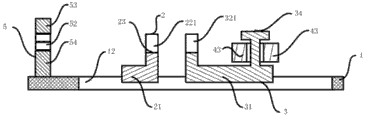
Fig. 1 illustrates according to first embodiment of the present utility model, the help pull a cart plan structure figure of plumber's dress of the special use that novel cable does not have the processing of gum cover pipe.Particularly, in the present embodiment, the special use that described novel cable the does not have gum cover pipe processing plumber's dress of helping pull a cart comprises workbench 1, wherein, described workbench 1 is provided with first stop member 2, second stop member 3, and rotatable parts 4, wherein, form first groove 23 between two first blocks 221 of described first stop member 2, form second groove 33 that groove face overlaps with the extended surface of described first groove, 23 groove faces between two second blocks 321 of described second stop member 3, described second stop member 3 is provided with litter 34, described litter 34 is positioned at the rail plate 44 of the cursor 43 of described rotatable parts 4, described second stop member 3 comprises second slide block 31, the part of described second slide block 31 is positioned at first guide rail 12 of described workbench 1, and described second stop member 3 can be free to slide in described first guide rail 12.
Preferably, described first stop member 2 comprises first slide block 21 and first locking piece, wherein, the part of described first slide block 21 is positioned at first guide rail 12 of described workbench 1, described first stop member 2 and described first guide rail, 12 relative fixed when described first locking piece is in latched position, described first stop member 2 can be free to slide in described first guide rail 12 when described first locking piece is in the unlocked position.For example, described first locking piece can be a lock screw, it is in latched position and makes described first stop member 2 not to be free to slide along described first guide rail 12 when screwing this lock screw, and it is in the unlocked position and makes described first stop member 2 to be free to slide along described first guide rail 12 when unscrewing this lock screw.
Preferably, described rotatable parts 4 comprise the base 41 that is connected on the described workbench 1, and described cursor 43 is connected on the described base 41 by first rotating shaft 42, described first rotating shaft 42 be axially perpendicular to described workbench 1.Like this, described cursor 43 can rotate in the plane that is parallel to described workbench 1, and orders about described second stop member 3 of described litter 34 drives by described rail plate 44 and slide along described first guide rail 12.
Preferably, described workbench 1 comprises second guide rail 11, described base 41 comprises the base slide block and second locking piece, wherein, described base slide block is positioned at described second guide rail 11, described base 41 and described second guide rail, 11 relative fixed when described second locking piece is in latched position, described base 41 can be free to slide in described second guide rail 11 when described second locking piece is in the unlocked position.For example, described second locking piece can be a lock screw, it is in latched position and makes described base 41 not to be free to slide along described second guide rail 11 when screwing this lock screw, and it is in the unlocked position and makes described base 41 to be free to slide along described second guide rail 11 when unscrewing this lock screw.
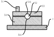
Preferably, help pull a cart plumber dress of described special use also comprises the cable gripping feature 5 that is arranged on the described workbench 1, wherein, as shown in Figure 9, described cable gripping feature 5 comprises lower clamp portion 54 and goes up clamp portion 53, a described end of going up clamp portion 53 is connected by second rotating shaft with an end of described lower clamp portion 54, and the axially parallel of described second rotating shaft is in described first guide rail 12.Further, the described clamp portion 53 that goes up can be movable between open position and clip position, when described last clamp portion 53 is positioned at described clip position, as shown in Figure 9, its the 3rd groove 531 that comprises forms a through hole 52, the axially parallel of described through hole 52 and described first guide rails 12 with the 4th groove 541 that described lower clamp portion 54 comprises.Preferably, the groove face of described the 4th groove 541 is a little more than the groove face of described first groove 23.Preferably, the described free end 532 of going up clamp portion 53 is provided with handle 51, and this is convenient to operator left-handed residence when the right hand rotates described cursor 43 and states handle 51 so that described workbench 1 is not subjected to displacement.
Fig. 2 illustrates according to first embodiment of the present utility model, the help pull a cart sectional structure chart of A-A line of plumber's dress of the special use of not having the processing of gum cover pipe along novel cable among Fig. 1.Particularly, in the present embodiment, as shown in Figure 2, the part of the part of described first slide block 21 and described second slide block 31 is positioned at first guide rail 12, thereby makes described first stop member 2 and second stop member 3 to slide along described first guide rail 12.
Next by describing conduit and starting taper in conjunction with Fig. 3, Fig. 4 and Fig. 7.Particularly, at first as shown in Figure 7, help pull a cart plumber dress of described special use comprises that also two ends are separately positioned on the conduit 6 in described first groove and second groove.Wherein, as shown in Figure 4, described conduit 6 comprises the centring ring 61 that is arranged on the one end, and the external diameter of described centring ring 61 is greater than the ultimate range between two described second blocks 321, and described centring ring 61 and described first stop member 2 lay respectively at the both sides of described second groove.More specifically, help pull a cart plumber dress of described special use also comprises starting taper 7, as shown in Figure 3, wherein, the inserted link 72 that described starting taper 7 comprises conical head 71 and is connected described conical head 71 tail ends, wherein, the diameter of described inserted link 72 is slightly less than the internal diameter of described conduit 6, and described starting taper 7 inserts in it from described conduit 6 non-ends that are provided with described centring ring by described inserted link 72.
Below in conjunction with Fig. 4 to Fig. 8 use principle of the present utility model is described.Particularly, at first the inserted link 72 with described starting taper 7 is inserted in the through hole 62 of described conduit 6, makes the outer wall of conical head 71 of described starting taper 7 and the outer wall smooth connection of described conduit 6.Next gum sleeve 8 is begun to move until being enclosed within on the described conduit 6 from conical head 71 1 ends, those skilled in the art understand, the internal diameter of gum sleeve 8 under nature is less than the external diameter of described sleeve pipe 6, thereby therefore by external diameter conical head 71 from fine to coarse gum sleeve 8 being expanded gradually is enclosed within on the described conduit 6, as shown in Figure 5.Described starting taper 7 is separated with described conduit 6, then cable 9 is passed from the through hole 62 of described conduit 6, as shown in Figure 6.Next of cable 9 is clamped with described cable gripping feature 5, as shown in Figure 7.Next, as shown in Figure 7, described cursor 43 is rotated to counterclockwise, like this, described second stop member 3 slides along described first guide rail 12 towards the direction away from described first stop member 2 under the driving of described cursor 43, at this moment described first stop member 2 and described first guide rail, 12 relative fixed, therefore described second block 321 is tight against the residence and states centring ring 61, described first block 221 is tight against the residence and states gum sleeve 8, thereby described gum sleeve 8 is broken away to described cable 9, as shown in Figure 8 from described conduit 6.
More than specific embodiment of the utility model is described.It will be appreciated that the utility model is not limited to above-mentioned specific implementations, those skilled in the art can make various distortion or modification within the scope of the claims, and this does not influence flesh and blood of the present utility model.