CN202041074U - Waste heat utilization device of kiln tube body of rotary kiln - Google Patents
Waste heat utilization device of kiln tube body of rotary kiln Download PDFInfo
- Publication number
- CN202041074U CN202041074U CN2011200321199U CN201120032119U CN202041074U CN 202041074 U CN202041074 U CN 202041074U CN 2011200321199 U CN2011200321199 U CN 2011200321199U CN 201120032119 U CN201120032119 U CN 201120032119U CN 202041074 U CN202041074 U CN 202041074U
- Authority
- CN
- China
- Prior art keywords
- collection case
- rotary kiln
- heat collector
- cylindrical shell
- outlet
- Prior art date
- Legal status (The legal status is an assumption and is not a legal conclusion. Google has not performed a legal analysis and makes no representation as to the accuracy of the status listed.)
- Expired - Lifetime
Links
Images


Classifications
-
- Y—GENERAL TAGGING OF NEW TECHNOLOGICAL DEVELOPMENTS; GENERAL TAGGING OF CROSS-SECTIONAL TECHNOLOGIES SPANNING OVER SEVERAL SECTIONS OF THE IPC; TECHNICAL SUBJECTS COVERED BY FORMER USPC CROSS-REFERENCE ART COLLECTIONS [XRACs] AND DIGESTS
- Y02—TECHNOLOGIES OR APPLICATIONS FOR MITIGATION OR ADAPTATION AGAINST CLIMATE CHANGE
- Y02P—CLIMATE CHANGE MITIGATION TECHNOLOGIES IN THE PRODUCTION OR PROCESSING OF GOODS
- Y02P10/00—Technologies related to metal processing
- Y02P10/25—Process efficiency
Landscapes
- Muffle Furnaces And Rotary Kilns (AREA)
Abstract
The utility model provides a waste heat utilization device of a kiln tube body of a rotary kiln. A heat collector of the waste heat utilization device is movably connected onto an upper crossbeam of a steel frame, wherein the circular arc shaped heat collector adaptive to the appearance of the upper half part of the kiln tube body of the rotary kiln is formed by n (n is larger than or equal to 1 and smaller than or equal to 40) mutually-connected units; the two ends of equilong water pipes in a membrane type duct piece of the heat collector units are respectively communicated with a collection box; one collection box is an inlet collection box, and the other collection box is an outlet collection box; and an air inlet nozzle is arranged on the inlet collection box, and a water outlet nozzle is arranged on the outlet collection box. The waste heat utilization device has the advantages that waste heat of the kiln tube body of the rotary kiln can be effectively utilized to produce hot water for heating, refrigeration or bathing, the structure of the device is simple, the cost is low, and the mounting is convenient.
Description
Technical field: the utility model relates to a kind of residual heat using device, particularly relates to a kind of rotary kiln cylindrical shell residual heat using device.
Background technology:The application of rotary kiln originates from manufacture of cement, is widely applied to many industrial circles at present.Rotary kiln is in operation process, the kiln cylinder body internal temperature is very high, although adopt various provision for thermal insulations (mainly being refractory brick and kliner coating at present), the kiln cylinder body hull-skin temperature is still very high, the kiln cylinder body surface temperature along kiln cylinder body axial distribution excursion between 120-400 ℃, mean temperature is about 270 ℃, and the radiation loss that brings thus accounts for clinker and burns till more than 10% of hear rate.A large amount of heat energy directly is dispersed in the atmosphere, and for also need blower fan that kiln cylinder body is lowered the temperature the service life that guarantees rotary kiln, this has not only wasted a large amount of heat energy, also contaminated environment during hot season.For this reason, domestic part cement production enterprise utilizes this part of waste heat to obtain life and heating hot water.The concrete structure of this residual heat using device is: adopt semi-enclosed heat shield, various forms of hot-water coil pipes are set in heat shield, coil pipe leans on the steelframe of half arc to be supported in the top of rotary kiln, feeds water in the coil pipe, reclaims the waste heat on the cylinder of rotary kiln.1), the device internal resistance is relatively large there is following drawback in the residual heat using device of this structure:, when especially system's water yield was big, resistance was very big, and the pump consumption is higher, uneconomical; 2), the coil pipe in the heat shield need rely on the stent support of half arc, just can stand on the top of cylinder of rotary kiln, comparatively speaking, the device consumptive material is more, and more complicated is installed; 3) used coil pipe is a light pipe, and therefore with respect to the kiln cylinder body of unit are, heating surface area is less, and the waste heat recovery rate is not high.
In recent years, everybody common concern that the recycling of rotary kiln radiation waste heat also causes, multinomial innovation and creation have been worked out, as disclosing the patent of invention of " a kind of cement rotary kiln barrel radiation recycle device " (application number is 200810059507.9) by name on state's Gazette of Patent for Invention in 22 days October in 2008, its structure mainly is: residual heat using device is provided with some heat exchange covers for segmentation on cylinder of rotary kiln, the heat exchange cover outer surface is provided with heat-insulation layer, be provided with sealing device between heat exchange cover two ends and the cylinder of rotary kiln, the inner surface of heat exchange cover and the outer surface of cylinder of rotary kiln form the sealing heat exchanging chamber by sealing device, and heat exchange cover bottom is provided with inlet tube, heat exchange cover top is provided with outlet.1), this residual heat using device is wrapped in inside fully with cylinder of rotary kiln the weak point of this invention is:, because the kiln cylinder body diameter generally surpasses 4 meters, the processing of so big sealing device sealing surface is difficult to realize, and the installation of package unit is very difficult; 2), utilize this device after, can not detect the cylinder of rotary kiln outside wall temperature that is wrapped in hollow shell inside, and then can not monitor working conditions change in the kiln; 3), this device is installed and maintenance is complicated, if during the rotary kiln maintenance, this device hinders the rotary kiln maintenance easily, causes the repair time to increase.
Summary of the invention:The purpose of this utility model is to provide a kind of waste heat, utilization rate of waste heat height that can effectively utilize the rotary kiln cylindrical shell, and simple in structure, cost is low, installs, overhauls rotary kiln cylindrical shell residual heat using device easily.
The utility model mainly is made up of heat collector and steelframe, wherein, steelframe is the framework of being made up of column and crossbeam that is located at the kiln cylinder body both sides, heat collector is movably connected on the entablature of steelframe, with convenient for maintaining with according to the spacing between seasonal adjustment heat collector madial wall and the cylinder of rotary kiln outer wall, preferably spacing is the 150-500 millimeter.Being made up of the n that links to each other (1≤n≤40) heat collector unit with the corresponding circular arc heat collector of rotary kiln cylindrical shell first half profile, can connect mutually in these unit, and the water inlet pipe and water outlet pipe of two promptly adjacent unit links to each other; Also can be in parallel, i.e. each unit water inlet does not link to each other mutually with outlet pipe.Preferably the mobile general direction of water is pressed water temperature and consistent layout of rotary kiln cylindrical shell axial temperature in the heat collector in the heat collector, be that the water at low temperature inlet is positioned at kiln cylinder body temperature lower region, the high-temperature water outlet is positioned at the kiln cylinder body areas of higher temperature, and this arrangement can improve the collecting efficiency of heat collector effectively.Above-mentioned heat collector unit mainly includes: membrane type section of jurisdiction, inlet collection case, outlet collection case, Inlet and outlet water are taken over.Wherein, the membrane type section of jurisdiction is that some water pipes arranged side by side are connected to form plate and pipe all-in-one-piece laminated structure by diaphragm (being sheet metal), it can be some water pipes arranged side by side with sides that are welded in a membrane type sheet (being sheet metal), also can be adjacent two water pipes respectively with strip membrane type sheet (being sheet metal) the two ends formation that is weldingly connected.The long water pipe two ends of waiting in the above-mentioned membrane type section of jurisdiction respectively are connected with a collection case, and one of them collection case collects case for inlet, and another collection case is outlet collection case.Above-mentioned collection case is the hollow housing of sealing, which is provided with corresponding with membrane type section of jurisdiction upper hose and coupled through hole.On inlet collection case, be provided with into water adapter, on outlet collection case, be provided with water outlet and take over.Be preferably in and be provided with discontinuously in above-mentioned inlet collection case or the outlet collection case and collect case cross section branch journey plate identical, that link to each other with the collection case all around, it can be divided into heat collector inside 2-20 pipe flow process, making within it, the flowing liquid flow velocity reaches optimum value, drag losses can be not excessive when not only heat transfer efficiency height, and fluid was flowed through pipeline.Be preferably in above-mentioned heat collector unit outer surface and be provided with adiabator layer,, outside this adiabator layer, be provided with coloured silk (approaching) steel plate or galvanized sheet its coating as rock wool blanket or alumina silicate fiber felt.Be preferably in above-mentioned membrane type section of jurisdiction and collect the case outer surface and establish high temperature resistant black oil enamelled coating.Above-mentioned heat collector unit can be that inlet collection case and outlet collection case are circular arc, and water pipe is a straight tube; Also can be that inlet collection case and outlet collection case are straight case, water pipe be a circular arc.
The course of work of the present utility model is as follows: water at low temperature is taken over the inlet header case that enters each heat collector unit by water inlet, distribute in the water pipe that flows into each membrane type section of jurisdiction then, rotary kiln drum surface heat energy is passed to heat collector by the mode of convection current and radiation, after water in the heat collector absorbs the waste heat intensification of kiln cylinder body, compile at outlet collection case, send by discharge connection then.
The utility model compared with prior art has following advantage:
1, heat collector inner fluid resistance is little, and power consumption is few, saves the energy.
2, the membrane type sheet not only connects water pipe, but also is the heat absorption fin, improves the collecting efficiency of heat collector.
3, simple in structure, installation, maintenance is all convenient.
Description of drawings
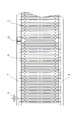
Fig. 1 is that the utility model user mode master looks simplified schematic diagram.
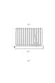
Fig. 2 is the utility model heat collector expanded view.
Fig. 3 is cross section, a utility model a kind of membrane type section of jurisdiction simplified schematic diagram.
Fig. 4 is cross section, the another kind of membrane type section of jurisdiction of a utility model simplified schematic diagram.
Fig. 5 is that the utility model circular arc collection case master looks simplified schematic diagram.
Fig. 6 is the A-A view of Fig. 5.
Fig. 7 the utility model directly collects the case master and looks simplified schematic diagram.
Fig. 8 is the B-B view of Fig. 7.
The specific embodimentLook in the simplified schematic diagram a kind of rotary kiln cylindrical shell residual heat using device user mode master shown in Figure 1, steelframe 1 is for being located at two door glyph framework being made up of column and crossbeam 3 of kiln cylinder body 2 both sides, heat collector 4 is movably connected on the entablature of steelframe, and spacing is the 150-500 millimeter.Being made up of two unit that link to each other with rotary kiln cylindrical shell first half profile corresponding circular arc heat collector, connects mutually in this Unit two.Preferably the mobile general direction of water is pressed water temperature and consistent layout of rotary kiln cylindrical shell axial temperature in the heat collector in the heat collector, and promptly the water at low temperature inlet is positioned at kiln cylinder body temperature lower region, and the high-temperature water outlet is positioned at the kiln cylinder body areas of higher temperature.In the utility model heat collector expanded view shown in Figure 2, the membrane type section of jurisdiction of above-mentioned heat collector unit can be that some water pipes arranged side by side 5 are sheet metal with being welded in a membrane type sheet 6() a side, as shown in Figure 3; Also can be adjacent two water pipes respectively with strip membrane type sheet (being sheet metal) the two ends formation that is weldingly connected, as shown in Figure 4.The long water pipe two ends of waiting in the above-mentioned membrane type section of jurisdiction respectively are connected with a collection case, and one of them collection case collects case 7 for inlet, and another collection case is outlet collection case 8.Above-mentioned collection case is the hollow housing of sealing, which is provided with corresponding with membrane type section of jurisdiction upper hose and coupled through hole.On inlet collection case, be provided with into water adapter 9, on outlet collection case, be provided with water outlet and take over 10.Be provided with discontinuously in inlet collection case or outlet collection case and collect case cross section branch journey plate 11 identical, that link to each other with the collection case all around above-mentioned, it can be divided into heat collector inside 2 and manage flow processs.Outer surface is provided with the alumina silicate fiber felt adiabator layer in above-mentioned heat collector unit.Outside this adiabator layer, be provided with coloured silk (approaching) steel plate or galvanized sheet with its coating.Establish high temperature resistant black oil enamelled coating in above-mentioned membrane type section of jurisdiction and collection case outer surface.Above-mentioned heat collector unit can be that inlet collection case and outlet collection case are circular arc, and water pipe is a straight tube, as shown in Figure 5 and Figure 6; Also can be that inlet collection case and outlet collection case are straight case, water pipe be a circular arc, as shown in Figure 7 and Figure 8.
Claims (7)
1. rotary kiln cylindrical shell residual heat using device, its heat collector is movably connected on the entablature of steelframe, it is characterized in that: form by the n that links to each other 1≤n≤40 heat collector unit with the circular arc heat collector that rotary kiln cylindrical shell first half profile adapts, the membrane type section of jurisdiction of above-mentioned heat collector unit is that water pipe arranged side by side is connected to form plate and pipe all-in-one-piece laminated structure by diaphragm, and these etc. the long water pipe two ends each with one the collection case be connected, one of them collection case is inlet collection case, another collection case is outlet collection case, on inlet collection case, be provided with into water adapter, on outlet collection case, be provided with water outlet and take over.
2. a kind of rotary kiln cylindrical shell residual heat using device according to claim 1 is characterized in that: above-mentioned heat collector unit can be that inlet collection case and outlet collection case are circular arc, and water pipe is a straight tube; Also can be that inlet collection case and outlet collection case are straight case, water pipe be a circular arc.
3. a kind of rotary kiln cylindrical shell residual heat using device according to claim 2, it is characterized in that: above-mentioned membrane type section of jurisdiction can be the side that water pipe arranged side by side is welded in a membrane type sheet together, also can be that two adjacent water pipes are weldingly connected with strip membrane type sheet two ends respectively side by side.
4. a kind of rotary kiln cylindrical shell residual heat using device according to claim 3 is characterized in that: be provided with discontinuously in above-mentioned inlet collection case or outlet collection case and collect case cross section branch journey plate identical, that link to each other with the collection case all around.
5. a kind of rotary kiln cylindrical shell residual heat using device according to claim 4, it is characterized in that: outer surface is provided with adiabator layer in above-mentioned heat collector unit.
6. a kind of rotary kiln cylindrical shell residual heat using device according to claim 5 is characterized in that: be provided with color steel or galvanized sheet with its coating in above-mentioned adiabator layer outside.
7. a kind of rotary kiln cylindrical shell residual heat using device according to claim 6 is characterized in that: establish high temperature resistant black oil enamelled coating in above-mentioned membrane type section of jurisdiction and collection case outer surface.
Priority Applications (1)
| Application Number | Priority Date | Filing Date | Title |
|---|---|---|---|
| CN2011200321199U CN202041074U (en) | 2011-01-30 | 2011-01-30 | Waste heat utilization device of kiln tube body of rotary kiln |
Applications Claiming Priority (1)
| Application Number | Priority Date | Filing Date | Title |
|---|---|---|---|
| CN2011200321199U CN202041074U (en) | 2011-01-30 | 2011-01-30 | Waste heat utilization device of kiln tube body of rotary kiln |
Publications (1)
| Publication Number | Publication Date |
|---|---|
| CN202041074U true CN202041074U (en) | 2011-11-16 |
Family
ID=44968514
Family Applications (1)
| Application Number | Title | Priority Date | Filing Date |
|---|---|---|---|
| CN2011200321199U Expired - Lifetime CN202041074U (en) | 2011-01-30 | 2011-01-30 | Waste heat utilization device of kiln tube body of rotary kiln |
Country Status (1)
| Country | Link |
|---|---|
| CN (1) | CN202041074U (en) |
Cited By (7)
| Publication number | Priority date | Publication date | Assignee | Title |
|---|---|---|---|---|
| CN102607260A (en) * | 2012-03-16 | 2012-07-25 | 杭州杭锅工业锅炉有限公司 | Rotary kiln waste heat recovering device with convection fin tubes structure |
| CN103148699A (en) * | 2011-12-06 | 2013-06-12 | 洛阳蓝海实业有限公司 | High-efficiency waste heat utilization device for cylinder surface of rotary kiln |
| CN103471411A (en) * | 2013-10-12 | 2013-12-25 | 攀枝花学院 | Waste heat recovery device for outer wall of cement rotary kiln |
| CN104930866A (en) * | 2015-06-09 | 2015-09-23 | 尹明和 | Cement kiln steam heat exchanger |
| CN106766962A (en) * | 2017-01-12 | 2017-05-31 | 中国科学院力学研究所 | A kind of rotary kiln tertiary-air pipe waste heat takes thermal |
| CN106839788A (en) * | 2017-01-12 | 2017-06-13 | 中国科学院力学研究所 | A kind of cement clinker production line waste heat comprehensive utilization system |
| CN111397383A (en) * | 2020-04-01 | 2020-07-10 | 郏县中联天广水泥有限公司 | Rotary kiln waste heat comprehensive utilization system |
-
2011
- 2011-01-30 CN CN2011200321199U patent/CN202041074U/en not_active Expired - Lifetime
Cited By (13)
| Publication number | Priority date | Publication date | Assignee | Title |
|---|---|---|---|---|
| CN103148699A (en) * | 2011-12-06 | 2013-06-12 | 洛阳蓝海实业有限公司 | High-efficiency waste heat utilization device for cylinder surface of rotary kiln |
| CN102607260B (en) * | 2012-03-16 | 2014-11-05 | 杭州杭锅工业锅炉有限公司 | Rotary kiln waste heat recovering device with convection fin tubes structure |
| CN102607260A (en) * | 2012-03-16 | 2012-07-25 | 杭州杭锅工业锅炉有限公司 | Rotary kiln waste heat recovering device with convection fin tubes structure |
| CN103471411B (en) * | 2013-10-12 | 2015-10-07 | 攀枝花学院 | Waste heat recovery device |
| CN103471411A (en) * | 2013-10-12 | 2013-12-25 | 攀枝花学院 | Waste heat recovery device for outer wall of cement rotary kiln |
| CN104930866B (en) * | 2015-06-09 | 2017-03-29 | 尹明和 | Cement kiln vapor heat exchanger |
| CN104930866A (en) * | 2015-06-09 | 2015-09-23 | 尹明和 | Cement kiln steam heat exchanger |
| CN106766962A (en) * | 2017-01-12 | 2017-05-31 | 中国科学院力学研究所 | A kind of rotary kiln tertiary-air pipe waste heat takes thermal |
| CN106839788A (en) * | 2017-01-12 | 2017-06-13 | 中国科学院力学研究所 | A kind of cement clinker production line waste heat comprehensive utilization system |
| CN106839788B (en) * | 2017-01-12 | 2019-06-21 | 中国科学院力学研究所 | A kind of cement clinker production line waste heat comprehensive utilization system |
| CN106766962B (en) * | 2017-01-12 | 2019-07-26 | 中国科学院力学研究所 | A kind of rotary kiln tertiary-air pipe waste heat takes thermal |
| CN111397383A (en) * | 2020-04-01 | 2020-07-10 | 郏县中联天广水泥有限公司 | Rotary kiln waste heat comprehensive utilization system |
| CN111397383B (en) * | 2020-04-01 | 2021-08-31 | 郏县中联天广水泥有限公司 | Rotary kiln waste heat comprehensive utilization system |
Similar Documents
| Publication | Publication Date | Title |
|---|---|---|
| CN202041074U (en) | Waste heat utilization device of kiln tube body of rotary kiln | |
| CN203671912U (en) | Water tank for air source heat pump water heater | |
| CN206563501U (en) | A kind of rotary kiln cement clinker production line waste heat recycling system | |
| CN201764469U (en) | Equipment for recycling flue gas waste heat of coke oven | |
| CN205119797U (en) | Energy -saving melting furnace | |
| CN102980423A (en) | Waste heat absorbing recoverer | |
| CN209445826U (en) | A kind of device for rotary kiln UTILIZATION OF VESIDUAL HEAT IN | |
| CN103206720A (en) | Positive pressure sealing method and positive pressure sealing system for rotary air preheater | |
| CN103486871B (en) | Melting furnace chimney with waste heat recovery structure | |
| CN204694122U (en) | A kind of a heatable brick bed road fume hot-water heat exchanger | |
| CN204477685U (en) | The recycling residual heat gasification installation of liquid gas | |
| CN107013963A (en) | A kind of abandoned mine low concentration gas utilizes simple waste gas residual-heat heating device | |
| CN203798205U (en) | Industrial waste gas waste heat-recycling heat exchanging device | |
| CN113175827A (en) | Waste heat gathering device and smelting furnace waste heat grading efficient utilization system | |
| CN207180441U (en) | A kind of heating furnace heat pipe type waste heat reclaiming device | |
| CN204240785U (en) | A kind of rotary kiln collector mat | |
| CN103868377B (en) | Industrial waste gas waste heat recovery heat-exchanger rig | |
| CN201697504U (en) | Heat regenerator | |
| CN203224154U (en) | Waste heat absorption recoverer | |
| CN203231296U (en) | U-type radiant tube assembly structure | |
| CN203518238U (en) | Vehicle-mounted horizontal fuel oil and fuel gas molten salt furnace | |
| CN102889635B (en) | A kind of global formation no-welding-seam radiator and production method thereof | |
| CN208704468U (en) | A kind of kiln hood exhaust piping | |
| CN201803620U (en) | Round tube type air heat exchange pipe | |
| CN203479030U (en) | Melting furnace chimney with waste heat recovery structure |
Legal Events
| Date | Code | Title | Description |
|---|---|---|---|
| C14 | Grant of patent or utility model | ||
| GR01 | Patent grant | ||
| CP03 | Change of name, title or address |
Address after: Floor 20, block B, No. 32a, Torch Road, high tech Industrial Park, Dalian, Liaoning Province, 116000 Patentee after: Lida Group Co., Ltd Address before: 116023 No. 2-1 student street, hi tech park, Liaoning, Dalian Patentee before: DALIAN EAST NEW ENERGY DEVELOPMENT Co.,Ltd. |
|
| CP03 | Change of name, title or address | ||
| CX01 | Expiry of patent term |
Granted publication date: 20111116 |
|
| CX01 | Expiry of patent term |