CN202009604U - Novel non-pressure irrigation device - Google Patents
Novel non-pressure irrigation device Download PDFInfo
- Publication number
- CN202009604U CN202009604U CN2011200607088U CN201120060708U CN202009604U CN 202009604 U CN202009604 U CN 202009604U CN 2011200607088 U CN2011200607088 U CN 2011200607088U CN 201120060708 U CN201120060708 U CN 201120060708U CN 202009604 U CN202009604 U CN 202009604U
- Authority
- CN
- China
- Prior art keywords
- water
- supply tank
- water supply
- level control
- water level
- Prior art date
- Legal status (The legal status is an assumption and is not a legal conclusion. Google has not performed a legal analysis and makes no representation as to the accuracy of the status listed.)
- Expired - Lifetime
Links
Images
Landscapes
- Cultivation Receptacles Or Flower-Pots, Or Pots For Seedlings (AREA)
Abstract
The utility model relates to a novel non-pressure irrigation device. When a water outlet valve gate of a water supply tank is opened, irrigation water flows into a water level control pool. When the water level of the pool exceeds h1, an air inlet pipe is submerged and air inlet is changed into water inlet. Until the water level in the air inlet pipe is equal to that in the water supply tank, the irrigation water stops flowing in the water level control pool and the water level of the pool is stable at a level slightly higher than h1. The irrigation water flows from the bottom of a U-shaped groove of a irrigation machine and enters a filling area at the upper part of a U-shaped groove through a permeable cover plate and a sandstone inverted filter, and a soil saturation water layer which is equal to the water level control pool in terms of water level and lower than the upper edge of the U-shaped grove. Water of the saturation water layer rises to a crop root layer in a manner of capillary water. With the water consumption of crops, the water level in the water level control pool is lower than h1. The air inlet pipe appears outside of a water surface and air flows in in a manner of bubbles. The irrigation water flows in the water level control pool again, and the water level rises to submerge the air inlet pipe again. The utility model is advantageous in that the water consumption of crops causes the water supply process to repeat; the water supply amount increases and reduces with the water consumption amount; a self-adaptive irrigation is achieved; the operation is simple and the use is convenient.
Description
Technical field:
The utility model relates to a kind of field irrigation device, relates in particular to a kind of novel nothing and presses irrigation rig.
Background technology:
The so-called nothing of the present invention is pressed and is irrigated, be to come by the definition amplification that negative pressure is irrigated, it is the elevation that the elevation of source of irrigation water is lower than irrigator, delivery head is a negative value during operation, being called negative pressure irrigates, as its name suggests, do not have to press irrigating is a kind of irrigation method that the elevation of source of irrigation water equates with the elevation of irrigator.It is to utilize the water potential energy difference and the capillarity of soil, plant, atmosphere to irrigate that negative pressure is irrigated, and is most effective up to now irrigation method.The irrigation process is carried out automatically, need not to carry out the decision-making of irrigation time and irrigation volume, how much water just to supply how much water with.Effectively suppressed native table evaporation, the negative pressure irrigated soil do not have gravitational water, deep percolation can not take place, and have solved the invalid irrigation and the nutrient loss problem that cause because of irrigation method.Do not describe with " good rain is known the time, and it is carefully noiseless to moist all things on earth " and to be.But negative pressure is irrigated and to be implemented very difficulty, the one, the sealing of water-carriage system there is very strict requirement, and can not leak gas, in case under ground portion bad seals is especially searched and keeped in repair very difficult; The 2nd, the gas that is dissolved under negative pressure condition in the water will be separated out, if untimely processing will produce cutout.Therefore, need regularly exhaust, and exhaust process complicated and trouble very, it is consuming time to require great effort, and has also increased managerial difficulty simultaneously; The 3rd, it is too small that negative pressure irrigator its specific structure (precondition of negative pressure irrigator and soil water exchange is that outer wall energy forms permeable air-locked moisture film) makes it water yield, ground moistening is limited in scope, can only be by increasing the method that the negative pressure irrigator is arranged density or increased single negative pressure irrigator water supply face, improve the moistening uniformity, making to drop into increases, and safeguards difficulty more; The 4th, the negative pressure irrigator is different with the soil texture, and discontinuous, the not of uniform size interface that causes of tangible hole is arranged, and whether unobstructed, also will depend on the tightness degree that the negative pressure irrigator contacts with soil if supplying water, have certain uncertainty.Original negative pressure irrigation system does not have the irrigation of pressure state even can adjust to, and the problems referred to above can not fundamentally solve, and develops novel nothing and presses irrigation rig, will become an inevitable choice.
The utility model content:
It is same efficient that the purpose of this utility model is to provide a kind of and negative pressure to irrigate, and use convenient, good endurance, a kind of novel nothing that reliability is high is pressed irrigation rig.
The purpose of this utility model is achieved in that
A kind of novel nothing is pressed irrigation rig, comprise: water supply tank, water level control pond, delivery main, collecting pipe, irrigator is some, water supply tank is positioned at the top in water level control pond, several irrigators are communicated with water level control pond by the collecting pipe delivery main, several irrigators vertically are parallel to each other and leave suitable spacing and are connected with collecting pipe is vertical, be co-located under the crop root layer on the same horizontal plane, guaranteeing under the prerequisite that the crop root layer effectively supplies water, increase this horizontal plane as far as possible and be positioned at the degree of depth under the crop root layer, to reduce soil table invalid evaporation, soil is fine and close more, capillarity is strong more, the degree of depth is big more, clay loam is greater than loam, loam is greater than sandy loam, in the place that differential settlement might take place, can increase the irrigator of cross connection, form the irrigator net, irrigator is by U type groove, water fender before the U type groove, water fender behind the U type groove, permeable cover plate, the sandstone loaded filter is formed, U type channel opening is placed perpendicular to horizontal plane up, that end that U type groove leads to collecting pipe is provided with the preceding water fender of U type groove, the other end is provided with water fender behind the U type groove, horizontal positioned permeable cover plate in middle and lower part in the U type groove groove, lay the sandstone loaded filter on the permeable cover plate, earthing consistent indifference contact with crop root layer soil on the sandstone loaded filter to ground, permeable cover plate is the filling drainage channel in the cavity down in the U type groove groove, filling drainage channel and soil carry out the water exchange and are undertaken by permeable cover plate and sandstone loaded filter, only allow water to move and do not allow solid particles such as soil to move, U type groove concrete, the built-in tension reinforcement in bottom, permeable cover plate non-fine concrete, water level control pond is provided with water-level control apparatus, water-level control apparatus is by atmospheric pressure communicating pipe, the water supply tank air inlet pipe, the water supply tank outlet pipe, the water supply tank flowing water Valve is formed, the upper end of water supply tank air inlet pipe is bent downwardly with the top of water supply tank and links to each other, make the peak of water supply tank air inlet pipe be higher than the top of water supply tank, the lower end of water supply tank air inlet pipe puts in water level control pond, port is positioned at the h1 place, h1 is suitable is lower than U type groove cell wall upper edge height h2, the lower end port of atmospheric pressure communicating pipe is suitable is higher than h1, the upper end of atmospheric pressure communicating pipe is bent downwardly after stretching out the suitable height in water level control pond, port down, the upper end of water supply tank outlet pipe links to each other with the bottom of water supply tank through the water supply tank flowing water Valve, the lower end of water supply tank outlet pipe puts in water level control pond, port is suitable is lower than h1, water supply tank 1 is provided with water filling device, water filling device is by the water supply tank water injection pipe, the water supply tank Water filling valve, the water supply tank water filling port is formed, water supply tank water injection pipe lower end links to each other with the bottom of water supply tank, the upper end links to each other with water supply tank water filling port bottom through the water supply tank Water filling valve, the upper edge, top and the water supply tank top of water supply tank water filling port are contour, water supply tank is a hermetically sealed can, the water supply tank water injection pipe that links to each other with water supply tank, the water supply tank air inlet pipe, the water supply tank Water filling valve, the water supply tank flowing water Valve will guarantee favorable sealing property.
The water supply tank the injecting process is as follows: close the water supply tank flowing water Valve, open the water supply tank Water filling valve, inject irrigation water from the water supply tank water filling port, till irrigation water overflows from the upper edge, top of water supply tank water filling port, close the water supply tank Water filling valve, finish the injecting process.
Irrigator water-filling and automatic irrigation process are as follows: open the water supply tank flowing water Valve, the water supply tank flowing water Valve of irrigation water in the water supply tank through opening flows into water level control pond, lower port air inlet from the water supply tank air inlet pipe, the process that makes irrigation advance go into water level control pond is continued, the water level in water level control pond is raised gradually, irrigation water enters the bottom intake tunnel in the U type groove groove of several irrigators that communicate with it by the delivery main collecting pipe, before U type groove behind water fender and the U type groove under the stopping of water fender, the irrigation water that water level continues to raise, by permeable cover plate and sandstone loaded filter, enter the zone of banketing of U type groove groove internal upper part, water level when water level control pond surpasses h1, the lower port of water supply tank air inlet pipe is submerged, the lower port of water supply tank air inlet pipe changes into water into by air inlet, water level and the water level in the water supply tank in the water supply tank air inlet pipe are contour, the lower port water inlet of water supply tank air inlet pipe stops, irrigation water in the water supply tank also stops to flow into water level control pond, the stable level in water level control pond is on the water level a little more than h1, the zone of banketing at U type groove groove internal upper part, formed and the contour soil saturation water layer of water level control pool water level, because of the suitable cell wall upper edge height h2 that has been lower than U type groove of h1, the gravitational water of soil saturation water layer is bound in the groove of U type groove, can not produce the gravitational water seepage loss, under soil capillarity, the water of soil saturation water layer in the U type groove groove, form with capillary water, rise to the crop root layer, the a spot of water of depolarization can continue to rise to outside the evaporation of soil table, the water of the overwhelming majority, after arriving the crop root layer, because soil, plant, the effect of the water potential energy difference of atmosphere, finally the form with the crop plant transpiration is delivered in the atmosphere, the crop plant transpiration has consumed the water of the soil saturation water layer in the U type groove groove, soil saturation water layer height in the U type groove groove is descended, and the water level in water level control pond also descends thereupon, when water level is lower than h1, the lower port of water supply tank air inlet pipe is surfaced, beginning is with the form air inlet of bubble, and the irrigation water in the water supply tank begins to flow into water level control pond again, and the water level in water level control pond raises, again flood the lower port of water supply tank air inlet pipe, air inlet stops, and the irrigation water in the water supply tank stops to flow into water level control pond again, and the crop water consumption causes the water level depression in water level control pond, the lower port of water supply tank air inlet pipe is surfaced, beginning is with the form air inlet of bubble, and the irrigation water in the water supply tank begins to flow into water level control pond again, and the water level in water level control pond raises, again flood the lower port of water supply tank air inlet pipe, air inlet stops, and the irrigation water in the water supply tank stops to flow into water level control pond again, and the crop water consumption causes above-mentioned water supply process ceaselessly to be repeated, in water supply process, the water level in water level control pond fluctuates a little around h1, and the water level in the water supply tank air inlet pipe together descends with the water level in the water supply tank, if vertical section of water supply tank air inlet pipe is transparent, can directly observe the water level depression degree of intake process and water supply tank, whether normal whether judge operation and decision to the water supply tank water filling, rainfall will make the soil saturation water layer be higher than h1, and the water level in water level control pond also is higher than h1 thereupon, supply water and stop automatically, be lower than h1 up to the soil saturation water layer, supply water and recover automatically, the crop water consumption causes water supply, make how much water of material consumption, just for how much water, output increases and decreases with water consumption, self adaptation, need not human intervention and artificial external energy, realized irrigation automation cheaply.
The utlity model has following good effect:
What common infiltrating irrigation was adopted is that the intermittent water application of pressure mode is arranged, because water is a kind of elastomer, when stopping to supply water, pressure oscillation is violent, is easy to negative pressure occur at apopore, sucks soil particle, causes apopore to stop up.The intermittent water application mode also is the major reason that crop root stops up apopore, because root system of plant hydrotropism growth characteristics, the back ground moistening scope that stops to supply water is shunk to apopore gradually, because the existence of soil moisture gradient, root system of plant is also being followed to the apopore extension in order to obtain moisture, finally stops up apopore.And novel nothing of the present invention is pressed irrigation rig, and flowing of water is very slow, and under the effect of loaded filter and non-fine concrete, soil particle can not move, and can not take place to stop up and alluvial.Novel nothing of the present invention is pressed irrigation rig, has the soil saturation water layer, even there is root system to enter the soil saturation water layer, does not lose the direction of growth because of there being the soil moisture gradient, can not pass through the soil saturation water layer and enter loaded filter, and the root system blockage problem takes place.
Common infiltrating irrigation is except physics stops up, and the most unreasonable dissolving salt that surely belongs to is separated out chemistry obstruction and the biological obstruction of bacterium class, does not have good way to solve so far.And novel nothing of the present invention is pressed irrigation rig, and the non-fine concrete porous disc of employing, sandstone loaded filter can not find out dissolving salt and separate out the record that chemistry stops up, bacterium class biology stops up in existing document.According to one's analysis, possible reason is: non-fine concrete, the distinctive hole of sandstone loaded filter are circuitous dendritic stereochemical structure, can gang up mutually after moisture enters, so even most of hole is blocked, still can keep suitable water penetration.Novel nothing of the present invention is pressed irrigation rig, river constructions such as the U-shaped concrete pit that adopts, non-fine concrete porous disc, sandstone loaded filter are commonly used, draw materials easily, and cost is not high, it is convenient to build, and key is that its reliability and durability are confirmed by the long-term practice of river construction.
It all is to utilize the water potential energy difference and the capillarity of soil, plant, atmosphere to irrigate that novel nothing of the present invention presses irrigation rig and negative pressure to irrigate, and is most effective up to now irrigation method.The irrigation process is carried out automatically, need not to carry out the decision-making of irrigation time and irrigation volume, how much water just to supply how much water with.The negative pressure irrigated soil do not have gravitational water, deep percolation can not take place.Novel nothing of the present invention is pressed irrigation rig, though soil has gravitational water---the soil saturation water layer, but be bound in the U type groove, there are not the deep percolation that common infiltrating irrigation may occur and the situation of nutrient loss, the evaporation of soil table is also very limited, the height of water use efficiency is that any other irrigation method institute is inaccessible.The energy consumption of the water potential energy difference of soil, plant, atmosphere is come to solar radiant energy, energy-saving and environmental protecting.But negative pressure is irrigated and to be implemented very difficulty, the one, the sealing of water-carriage system there is very strict requirement, and can not leak gas, in case under ground portion bad seals is especially searched and keeped in repair very difficult; The 2nd, the gas that is dissolved under negative pressure condition in the water will be separated out, if untimely processing will produce cutout.Therefore, need regularly exhaust, and exhaust process complicated and trouble very, it is consuming time to require great effort, and has also increased managerial difficulty simultaneously; The 3rd, it is too small that negative pressure irrigator its specific structure (precondition of negative pressure irrigator and soil water exchange is that outer wall energy forms permeable air-locked moisture film) makes it water yield, ground moistening is limited in scope, can only be by increasing the method that the negative pressure irrigator is arranged density or increased single negative pressure irrigator water supply face, improve the moistening uniformity, making to drop into increases, and safeguards difficulty more; The 4th, the negative pressure irrigator is different with the soil texture, and discontinuous, the not of uniform size interface that causes of tangible hole is arranged, and whether unobstructed, also will depend on the tightness degree that the negative pressure irrigator contacts with soil if supplying water, have certain uncertainty.And novel nothing of the present invention is pressed irrigation rig, atmospheric pressure supplies water down, soil saturation water layer in the irrigator and its top soil texture that supplied water is the same, hole is consistent continuously, soil capillarity has performed to ultimate attainment, and it is unobstructed to supply water, and feedwater is sufficient, under the situation of the same moistening uniformity, can reduce the layout density of irrigator.Under ground portion need not additional seal, also need not special exhaust apparatus is set, and is simple to operate, easy to use.
Because supplying water, the present invention adopted law of connected vessels, the head unanimity, and according to Darcy's law, soil saturation water layer height is also consistent, and the water supply uniformity is very high.Even and common infiltrating irrigation has been installed flow regulating equipment additional and also can't have been reached so high water supply uniformity.
The underground plastic delivery hose of common infiltrating irrigation road suffers damaged by rats easily.And groundwater supply device of the present invention, there is the soil saturation water layer on top as barrier, and bottom and side are concrete, and mouse has no interest, and also gnaws motionless.
Description of drawings:
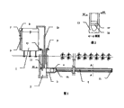
Fig. 1 is the schematic diagram that novel nothing is pressed irrigation rig.
Fig. 2 is the A-A profile among Fig. 1.
Embodiment:
A kind of novel nothing is pressed irrigation rig, as Fig. 1, shown in Figure 2, comprise: water supply tank 1, water level control pond 2, delivery main 3, collecting pipe 4, irrigator 5 is some, water supply tank 1 is positioned at the top in water level control pond 2, several irrigators 5 are communicated with water level control pond 2 by collecting pipe 4 delivery mains 3, several irrigators 5 vertically are parallel to each other and leave suitable spacing and 4 vertical connections of collecting pipe, be co-located under the crop root layer on the same horizontal plane, guaranteeing under the prerequisite that the crop root layer effectively supplies water, increase this horizontal plane as far as possible and be positioned at the degree of depth under the crop root layer, to reduce soil table invalid evaporation, soil is fine and close more, capillarity is strong more, the degree of depth is big more, clay loam is greater than loam, loam is greater than sandy loam, in the place that differential settlement might take place, can increase the irrigator 5 of cross connection, form the irrigator net, irrigator 5 is by U type groove 13, water fender 14 before the U type groove, water fender 15 behind the U type groove, permeable cover plate 16, sandstone loaded filter 17 is formed, U type groove 13 openings are placed perpendicular to horizontal plane up, that end that U type groove 13 leads to collecting pipe 4 is provided with the preceding water fender 14 of U type groove, the other end is provided with water fender 15 behind the U type groove, horizontal positioned permeable cover plate 16 in middle and lower part in U type groove 13 grooves, lay sandstone loaded filter 17 on the permeable cover plate 16, earthing consistent indifference contact with crop root layer soil on the sandstone loaded filter 17 to ground, 16 times cavities of permeable cover plate are for irritating drainage channel in U type groove 13 grooves, filling drainage channel and soil carry out the water exchange and are undertaken by permeable cover plate 16 and sandstone loaded filter 17, only allow water to move and do not allow solid particles such as soil to move, U type groove 13 is used concrete, the built-in tension reinforcement in bottom, permeable cover plate 16 is used non-fine concrete, water level control pond 2 is provided with water-level control apparatus, water-level control apparatus is by atmospheric pressure communicating pipe 9, water supply tank air inlet pipe 10, water supply tank outlet pipe 11, water supply tank flowing water Valve 12 is formed, the upper end of water supply tank air inlet pipe 10 is bent downwardly with the top of water supply tank 1 and links to each other, make the peak of water supply tank air inlet pipe 10 be higher than the top of water supply tank 1, the lower end of water supply tank air inlet pipe 10 puts in water level control pond 2, port is positioned at the h1 place, h1 is suitable is lower than U type groove 13 cell wall upper edge height h2, the lower end port of atmospheric pressure communicating pipe 9 is suitable is higher than h1, the upper end of atmospheric pressure communicating pipe 9 is bent downwardly after stretching out water level control pond 2 suitable height, port down, the upper end of water supply tank outlet pipe 11 links to each other through the bottom of water supply tank flowing water Valve 12 with water supply tank 1, the lower end of water supply tank outlet pipe 11 puts in water level control pond 2, port is suitable is lower than h1, water supply tank 1 is provided with water filling device, water filling device is by water supply tank water injection pipe 6, water supply tank Water filling valve 7, water supply tank water filling port 8 is formed, water supply tank water injection pipe 6 lower ends link to each other with the bottom of water supply tank 1, the upper end links to each other with water supply tank water filling port 8 bottoms through water supply tank Water filling valve 7, the upper edge, top and water supply tank 1 top of water supply tank water filling port 8 are contour, water supply tank 1 is a hermetically sealed can, the water supply tank water injection pipe 6 that links to each other with water supply tank 1, water supply tank air inlet pipe 10, water supply tank Water filling valve 7, water supply tank flowing water Valve 12 will guarantee favorable sealing property.
Water supply tank 1 the injecting process is as follows: close water supply tank flowing water Valve 12, open water supply tank Water filling valve 7, inject irrigation water from water supply tank water filling port 8, till irrigation water overflows from the upper edge, top of water supply tank water filling port 8, close water supply tank Water filling valve 7, finish the injecting process.
Irrigator water-filling and automatic irrigation process are as follows: open water supply tank flowing water Valve 12, the water supply tank flowing water Valve 12 of irrigation water in the water supply tank 1 through opening flows into water level control pond 2, lower port air inlet from water supply tank air inlet pipe 10, the process that makes irrigation advance go into water level control pond 2 is continued, the water level in water level control pond 2 is raised gradually, irrigation water enters the bottom intake tunnel in U type groove 13 grooves of several irrigators 5 that communicate with it by delivery main 3 collecting pipes 4, before U type groove behind water fender 14 and the U type groove under the stopping of water fender 15, the irrigation water that water level continues to raise, by permeable cover plate 16 and sandstone loaded filter 17, enter the zone of banketing of U type groove 13 groove internal upper parts, water level when water level control pond 2 surpasses h1, the lower port of water supply tank air inlet pipe 10 is submerged, the lower port of water supply tank air inlet pipe 10 changes into water into by air inlet, water level in water level in water supply tank air inlet pipe 10 and the water supply tank 1 is contour, the lower port water inlet of water supply tank air inlet pipe 10 stops, irrigation water in the water supply tank 1 also stops to flow into water level control pond 2, the stable level in water level control pond 2 is on the water level a little more than h1, the zone of banketing at U type groove 13 groove internal upper parts, formed and the contour soil saturation water layer of water level control pond 2 water levels, because of the suitable cell wall upper edge height h2 that has been lower than U type groove 13 of h1, the gravitational water of soil saturation water layer is bound in the groove of U type groove 13, can not produce the gravitational water seepage loss, under soil capillarity, the water of soil saturation water layer in U type groove 13 grooves, form with capillary water, rise to the crop root layer, the a spot of water of depolarization can continue to rise to outside the evaporation of soil table, the water of the overwhelming majority, after arriving the crop root layer, because soil, plant, the effect of the water potential energy difference of atmosphere, finally the form with the crop plant transpiration is delivered in the atmosphere, the crop plant transpiration has consumed the water of the soil saturation water layer in U type groove 13 grooves, soil saturation water layer height in U type groove 13 grooves is descended, and the water level in water level control pond 2 also descends thereupon, when water level is lower than h1, the lower port of water supply tank air inlet pipe 10 is surfaced, beginning is with the form air inlet of bubble, and the irrigation water in the water supply tank 1 begins to flow into water level control pond 2 again, and the water level in water level control pond 2 raises, again flood the lower port of water supply tank air inlet pipe 10, air inlet stops, and the irrigation water in the water supply tank 1 stops to flow into water level control pond 2 again, and the crop water consumption causes the water level depression in water level control pond 2, the lower port of water supply tank air inlet pipe 10 is surfaced, beginning is with the form air inlet of bubble, and the irrigation water in the water supply tank 1 begins to flow into water level control pond 2 again, and the water level in water level control pond 2 raises, again flood the lower port of water supply tank air inlet pipe 10, air inlet stops, and the irrigation water in the water supply tank 1 stops to flow into water level control pond 2 again, and the crop water consumption causes above-mentioned water supply process ceaselessly to be repeated, in water supply process, the water level in water level control pond 2 fluctuates a little around h1, and the water level in the water supply tank air inlet pipe 10 together descends with the water level in the water supply tank 1, if vertical section of water supply tank air inlet pipe 10 is transparent, can directly observe the water level depression degree of intake process and water supply tank 1, whether normal whether judge operation and decision to water supply tank 1 water filling, rainfall will make the soil saturation water layer be higher than h1, and the water level in water level control pond 2 also is higher than h1 thereupon, supply water and stop automatically, be lower than h1 up to the soil saturation water layer, supply water and recover automatically, the crop water consumption causes water supply, make how much water of material consumption, just for how much water, output increases and decreases with water consumption, self adaptation, need not human intervention and artificial external energy, realized irrigation automation cheaply.
Claims (3)
1. a novel nothing is pressed irrigation rig, it is characterized in that: comprise water supply tank (1), water level control pond (2), delivery main (3), collecting pipe (4), irrigator (5) is some, water supply tank (1) is positioned at the top in water level control pond (2), several irrigators (5) are communicated with water level control pond (2) by collecting pipe (4) delivery main (3), several irrigators (5) vertically are parallel to each other and leave suitable spacing and vertical connection of collecting pipe (4), be co-located under the crop root layer on the same horizontal plane, in the place that differential settlement might take place, can increase the irrigator (5) of cross connection, form the irrigator net, irrigator (5) is by U type groove (13), water fender (14) before the U type groove, water fender (15) behind the U type groove, permeable cover plate (16), sandstone loaded filter (17) is formed, U type groove (13) opening is placed perpendicular to horizontal plane up, that end that U type groove (13) leads to collecting pipe (4) is provided with the preceding water fender (14) of U type groove, the other end is provided with water fender (15) behind the U type groove, the middle and lower part permeable earth mulch plate of horizontal positioned (16) in U type groove (13) groove, permeable cover plate (16) is gone up and is laid sandstone loaded filter (17), sandstone loaded filter (17) is gone up earthing consistent indifference contact with crop root layer soil to ground, permeable cover plate (16) is the filling drainage channel in the cavity down in U type groove (13) groove, filling drainage channel and soil carry out the water exchange and are undertaken by permeable cover plate (16) and sandstone loaded filter (17), only allow water to move and do not allow solid particles such as soil to move, water level control pond (2) is provided with water-level control apparatus, water-level control apparatus is by atmospheric pressure communicating pipe (9), water supply tank air inlet pipe (10), water supply tank outlet pipe (11), water supply tank flowing water Valve (12) is formed, the upper end of water supply tank air inlet pipe (10) is bent downwardly with the top of water supply tank (1) and links to each other, make the peak of water supply tank air inlet pipe (10) be higher than the top of water supply tank (1), the lower end of water supply tank air inlet pipe (10) puts in water level control pond (2), port is positioned at the h1 place, h1 is suitable is lower than U type groove (13) cell wall upper edge height h2, the lower end port of atmospheric pressure communicating pipe (9) is suitable is higher than h1, the upper end of atmospheric pressure communicating pipe (9) is stretched out water level control pond (2) and suitably is bent downwardly behind the height, port down, the upper end of water supply tank outlet pipe (11) links to each other through the bottom of water supply tank flowing water Valve (12) with water supply tank (1), the lower end of water supply tank outlet pipe (11) puts in water level control pond (2), port is suitable is lower than h1, water supply tank (1) is provided with water filling device, water filling device is by water supply tank water injection pipe (6), water supply tank Water filling valve (7), water supply tank water filling port (8) is formed, water supply tank water injection pipe (6) lower end links to each other with the bottom of water supply tank (1), the upper end links to each other with water supply tank water filling port (8) bottom through water supply tank Water filling valve (7), and the upper edge, top of water supply tank water filling port (8) and water supply tank (1) top are contour.
2. a kind of novel nothing according to claim 1 is pressed irrigation rig, it is characterized in that: described water supply tank (1) is a hermetically sealed can, and the water supply tank water injection pipe (6) that links to each other with water supply tank (1), water supply tank air inlet pipe (10), water supply tank Water filling valve (7), water supply tank flowing water Valve (12) will guarantee favorable sealing property.
3. a kind of novel nothing according to claim 1 is pressed irrigation rig, and it is characterized in that: described U type groove (13) is used concrete, the built-in tension reinforcement in bottom, and described permeable cover plate (16) is used non-fine concrete.
Priority Applications (1)
| Application Number | Priority Date | Filing Date | Title |
|---|---|---|---|
| CN2011200607088U CN202009604U (en) | 2011-03-10 | 2011-03-10 | Novel non-pressure irrigation device |
Applications Claiming Priority (1)
| Application Number | Priority Date | Filing Date | Title |
|---|---|---|---|
| CN2011200607088U CN202009604U (en) | 2011-03-10 | 2011-03-10 | Novel non-pressure irrigation device |
Publications (1)
| Publication Number | Publication Date |
|---|---|
| CN202009604U true CN202009604U (en) | 2011-10-19 |
Family
ID=44780211
Family Applications (1)
| Application Number | Title | Priority Date | Filing Date |
|---|---|---|---|
| CN2011200607088U Expired - Lifetime CN202009604U (en) | 2011-03-10 | 2011-03-10 | Novel non-pressure irrigation device |
Country Status (1)
| Country | Link |
|---|---|
| CN (1) | CN202009604U (en) |
Cited By (7)
| Publication number | Priority date | Publication date | Assignee | Title |
|---|---|---|---|---|
| CN102160518A (en) * | 2011-03-10 | 2011-08-24 | 中国农业科学院农田灌溉研究所 | Novel non-pressure irrigation rig |
| CN103262779A (en) * | 2013-06-11 | 2013-08-28 | 谭朝晖 | Capillary irrigator consisting of tightly stacked flat plates and tube body |
| CN104126487A (en) * | 2014-08-06 | 2014-11-05 | 昆明理工大学 | Adjustable underground alternate-irrigation device |
| CN105766567A (en) * | 2016-04-07 | 2016-07-20 | 邓洋 | Pressure-free irrigation device |
| CN105875358A (en) * | 2014-12-19 | 2016-08-24 | 遵义市紫璇酒业有限公司 | Pressing type layer irrigation device |
| CN111109047A (en) * | 2020-02-21 | 2020-05-08 | 周能为 | Agricultural automatic accurate irrigation system |
| CN111874971A (en) * | 2020-07-30 | 2020-11-03 | 宁波市天莱园林建设工程有限公司 | Garden water quality purification method and system |
-
2011
- 2011-03-10 CN CN2011200607088U patent/CN202009604U/en not_active Expired - Lifetime
Cited By (10)
| Publication number | Priority date | Publication date | Assignee | Title |
|---|---|---|---|---|
| CN102160518A (en) * | 2011-03-10 | 2011-08-24 | 中国农业科学院农田灌溉研究所 | Novel non-pressure irrigation rig |
| CN102160518B (en) * | 2011-03-10 | 2012-09-05 | 中国农业科学院农田灌溉研究所 | Novel non-pressure irrigation rig |
| CN103262779A (en) * | 2013-06-11 | 2013-08-28 | 谭朝晖 | Capillary irrigator consisting of tightly stacked flat plates and tube body |
| CN104126487A (en) * | 2014-08-06 | 2014-11-05 | 昆明理工大学 | Adjustable underground alternate-irrigation device |
| CN105875358A (en) * | 2014-12-19 | 2016-08-24 | 遵义市紫璇酒业有限公司 | Pressing type layer irrigation device |
| CN105766567A (en) * | 2016-04-07 | 2016-07-20 | 邓洋 | Pressure-free irrigation device |
| WO2017173745A1 (en) * | 2016-04-07 | 2017-10-12 | 严利容 | Pressureless irrigation apparatus |
| CN105766567B (en) * | 2016-04-07 | 2020-01-17 | 邓洋 | Non-pressure irrigation device |
| CN111109047A (en) * | 2020-02-21 | 2020-05-08 | 周能为 | Agricultural automatic accurate irrigation system |
| CN111874971A (en) * | 2020-07-30 | 2020-11-03 | 宁波市天莱园林建设工程有限公司 | Garden water quality purification method and system |
Similar Documents
| Publication | Publication Date | Title |
|---|---|---|
| CN102160518B (en) | Novel non-pressure irrigation rig | |
| CN202009604U (en) | Novel non-pressure irrigation device | |
| CN201976544U (en) | Automatic irrigation and drainage system for farm land | |
| US10154629B2 (en) | Pressureless irrigation device | |
| CN102144524A (en) | Automatic irrigation-drainage system for farmland | |
| CN101023732B (en) | Irrigation system | |
| CN105052683A (en) | System used for plant root system infiltrating irrigation and soil drainage | |
| CN206491110U (en) | A kind of stereo sand trains implant system | |
| CN104255396A (en) | Automatic paddy field irrigation device and system | |
| CN103262779B (en) | A kind of flat board is the superimposed capillary osmotic irrigation device be combined with body closely | |
| CN206851611U (en) | Crops field irrigation control system | |
| CN206196565U (en) | A kind of micro- energy consumption automatic irrigation system | |
| CN205105878U (en) | System for be used for plant roots permeation irrigation and soil body drainage | |
| CN202603312U (en) | Water-saving irrigation system | |
| CN207531569U (en) | A kind of bamboo seedling water planting self-loopa culture system | |
| CN206118679U (en) | Automatic regulation and control system is irrigated to energy -concerving and environment -protective negative pressure | |
| CN102150604B (en) | Shared plant liquid supplying system capable of automatically controlling liquid level | |
| CN204146126U (en) | A kind of agricultural irrigation device | |
| CN111512937B (en) | Timely irrigation system | |
| CN107950106A (en) | A kind of closed drainage in salt-soda soil-oxygen renewal double effect system | |
| CN210782367U (en) | Water-storage stable water pressure irrigation system | |
| CN209879960U (en) | Self-circulation device for testing utilization coefficient of furrow irrigation and furrow irrigation water | |
| CN208523310U (en) | A kind of wild rice stem implant system | |
| CN207032185U (en) | A kind of high-efficient irrigation coupling technique device based on full controlling channel system | |
| CN101785418A (en) | Plant cultivation watering device |
Legal Events
| Date | Code | Title | Description |
|---|---|---|---|
| C14 | Grant of patent or utility model | ||
| GR01 | Patent grant | ||
| AV01 | Patent right actively abandoned |
Granted publication date: 20111019 Effective date of abandoning: 20120905 |
|
| AV01 | Patent right actively abandoned |
Granted publication date: 20111019 Effective date of abandoning: 20120905 |