CN202004614U - Ironless and brushless permanent magnet DC (Direct Current) motor with inner and outer rotors - Google Patents
Ironless and brushless permanent magnet DC (Direct Current) motor with inner and outer rotors Download PDFInfo
- Publication number
- CN202004614U CN202004614U CN2011200234769U CN201120023476U CN202004614U CN 202004614 U CN202004614 U CN 202004614U CN 2011200234769 U CN2011200234769 U CN 2011200234769U CN 201120023476 U CN201120023476 U CN 201120023476U CN 202004614 U CN202004614 U CN 202004614U
- Authority
- CN
- China
- Prior art keywords
- bearing
- cup
- yoke
- direct current
- shaped
- Prior art date
- Legal status (The legal status is an assumption and is not a legal conclusion. Google has not performed a legal analysis and makes no representation as to the accuracy of the status listed.)
- Expired - Lifetime
Links
Images


Abstract
The utility model relates to an ironless and brushless permanent magnet DC (Direct Current) motor with inner and outer rotors, which comprises a cylindrical case, a rotor, a stator and an end cover combination, wherein the stator comprises a ring-shaped base with a first bearing, a ring-shaped PCB (Printed Circuit Board) wiring board arranged on one end surface of the ring-shaped base, a three-phase cylindrical coil winding, and a power line connected with the ring-shaped base; the end cover combination comprises a ring-shaped end cover with a second bearing; the rotor arranged in the case comprises a cup-shaped outer magnetic yoke, a rotating shaft connected with the cup-shaped outer magnetic yoke, outer magnetic steel arranged at the inner circle of the cup-shaped outer magnetic yoke, an inner magnetic yoke sheathed on the rotating shaft, and inner magnetic steel sheathed on the inner magnetic yoke; the three-shaped cylindrical coil winding is right inserted in a cylindrical air gas formed between the outer magnetic steel and the inner magnetic steel; the two ends of the rotating shaft are respectively arranged in the first bearing and the second bearing, a first sleeve is arranged between the first bearing and the inner magnetic yoke, and a second sleeve is arranged between the second bearing and the cup-shaped outer magnetic yoke. The utility model improves the power density, so that the motor can be further small and portable.
Description
Technical field
The utility model relates to electrical micro-machine, especially a kind of no iron core brush-less permanent magnetic direct current machine with inner and outer rotors.
Background technology
In recent years, the brush-less permanent magnetic direct current machine is long owing to its life-span, efficient is high, the characteristics of good speed adjustment features are widely used in all trades and professions such as industry, household electrical appliance, health care, model plane.But to the conventional brushless electric machine that runs up, the magnetic field of rotation produces eddy current loss in core interior, and motor miniaturization and high efficiency operation are restricted.
The utility model content
Of the present utility model in order to solve the existing technical problem that electrical micro-machine easily generates heat, efficient is lower and volume is bigger, a kind of efficient height, power is big, volume the is little no iron core brush-less permanent magnetic direct current machine with inner and outer rotors are proposed.
For addressing the above problem, a kind of no iron core brush-less permanent magnetic direct current machine with inner and outer rotors of proposition of the present utility model comprises coaxial mounted columnar casing, rotor, stator and end cap combination.
Described stator comprises: the circular base of described casing one end of capping, be located at the clutch shaft bearing in the circle in this circular base, be located at PCB terminal block and the three-phase solenoid coil winding of the annular of this circular base one end face, the power line that is connected with described this circular base;
The combination of described end cap comprises: the annular end cap of the described casing other end of capping, be located at second bearing in the circle in the annular end cap;
Described rotor is located in the casing, and it comprises: cup-shaped outer yoke, be connected with cup-shaped outer yoke and with the rotating shaft of the interior round coaxial inner conductor of this cup-shaped outer yoke, be located at outer steel on the cup-shaped outer yoke inner peripheral surface, be placed in the inner yoke in the described rotating shaft and be placed in interior magnet steel on this inner yoke;
Form cylindrical air gap between described outer steel and the interior magnet steel, just in time insert described three-phase solenoid coil winding in this cylindrical air gap; The two ends of described rotating shaft are installed on respectively in the endoporus of the described clutch shaft bearing and second bearing, are provided with second sleeve pipe and be provided with between clutch shaft bearing and the inner yoke between first sleeve pipe, second bearing and the cup-shaped outer yoke.
More excellent, described inside and outside magnet steel is multipole annular shape or by alternate being spliced of magnetic shoe of the several piece N utmost point, the S utmost point.
The number of poles of described inside and outside magnet steel can or be 2 multiple for 2.
Described inside and outside magnet steel is made by the high energy product NdFeB material.
Described casing is made by non-magnet material.
Described three-phase solenoid coil winding adopts any processing technology of crossing, coiling or the uniform arrangement of concentrating coil to make.
No iron core brush-less permanent magnetic direct current machine with inner and outer rotors has been cancelled the stator yoke iron core, and stator only is the three-phase solenoid coil winding of no iron core.In order to strengthen air gap flux density, rotor adopts the magnetic structure of inside and outside two groups of magnet steel simultaneously.The three-phase solenoid coil winding of stator can produce the electromagnetic force that makes motor continue rotation in the air gap that the inside and outside magnet steel of rotor constitutes and magnetic field interaction.The motor high speed rotating does not have the stator iron loss in addition, and high air gap flux density can make the motor of equal volume produce bigger moment.The power density of product be can improve simultaneously greatly, the further miniaturization of motor, portability made.
Description of drawings
The utility model is described in further detail below in conjunction with drawings and Examples, wherein:
Fig. 1 is the three-dimensional explosive view of the utility model preferred embodiment;
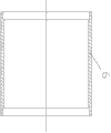
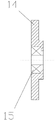
Fig. 2, Fig. 3, Fig. 4 and Fig. 5 are respectively the cutaway views of stator, casing, rotor and end cap combination in the utility model preferred embodiment;
Fig. 6 is the cutaway view after the assembling of the utility model preferred embodiment.
Embodiment
Fig. 1 and Fig. 6 show the basic structure of the utility model preferred embodiment, and described no iron core brush-less permanent magnetic direct current machine with inner and outer rotors, it comprises coaxial mounted columnar casing 6, rotor, stator and end cap combination.In conjunction with Fig. 2, shown in Figure 3, stator comprises: the circular base 1 of capping casing 6 left ends, be located at the clutch shaft bearing 5 in the circle in this circular base, be installed on the PCB terminal block 3 of the annular of this circular base 1 right side, be adhesively fixed in the three-phase solenoid coil winding 2 of circular base 1 right side.Lead-in wire and a power line 4 with three-phase solenoid coil winding 2 is welded on PCB terminal block 3 again.In conjunction with shown in Figure 5, end cap combination comprises: the annular end cap 14 of capping casing 6 right-hand members, be located at second bearing 15 in the circle in the annular end cap.In conjunction with shown in Figure 4, rotor is located in the casing 6, it comprise cup-shaped outer yoke 11, be connected with cup-shaped outer yoke and with the rotating shaft 7 of the interior round coaxial inner conductor of this cup-shaped outer yoke, be located at outer steel 10 on cup-shaped outer yoke 11 inner peripheral surfaces, be placed in the inner yoke 8 in the rotating shaft 7 and be placed in interior magnet steel 9 on this inner yoke 8.Form cylindrical air gap between outer steel 10 and the interior magnet steel 9, just in time insert three-phase solenoid coil winding 2 in this cylindrical air gap.The two ends of rotating shaft 7 are installed on respectively in the endoporus of the clutch shaft bearing 5 and second bearing 15, are provided with second sleeve pipe 13 and be provided with between clutch shaft bearing 5 and the inner yoke 8 between first sleeve pipe 12, second bearing 15 and the cup-shaped outer yoke 11.
Magnet steel 9, outer steel 10 are multipole annular shape in of the present utility model, can be by alternate being spliced of magnetic shoe of the several piece N utmost point, the S utmost point.The number of poles of interior magnet steel 9, outer steel 10 is 2 or 2 multiple.Interior magnet steel 9, outer steel 10 are made by the high energy product NdFeB material.Casing 6 is made by non-magnet material.Three-phase solenoid coil winding 2 adopts any processing technology of crossing, coiling or the uniform arrangement of concentrating coil to make.The magnetic field and the stator coil winding interaction generation electromagnetic push that produce by inside and outside magnet steel make the motor rotation.
Rotor of the present utility model is the magnetic structure of inside and outside two groups of magnet steel, and this structure can produce superpower air-gap field, increases the motor power output.Stator is the three-phase solenoid coil winding construction of no iron core, has avoided the generation of electric machine iron core eddy current loss, has reduced heating, the temperature rise of motor, and this motor do not have slot effect, and motor rotation is level and smooth, and vibration and noise are all had improvement.
Although the utility model and some advantages thereof are described in detail in the above-described embodiment; yet; the person of ordinary skill in the field should be realized that; within spirit of the present utility model and principle; can make any modification, improvement, expansion etc., these modifications, improvement, expansion all are encompassed within the protection range of the present utility model.
Claims (6)
1. the no iron core brush-less permanent magnetic direct current machine with inner and outer rotors comprises coaxial mounted columnar casing (6), rotor, stator and end cap combination, it is characterized in that:
Described stator comprises: the circular base (1) of described casing (6) one ends of capping, be located at the clutch shaft bearing (5) in the circle in this circular base, be located at PCB terminal block (3) and the three-phase solenoid coil winding (2) of the annular of this circular base one end face, the power line (4) that is connected with described this circular base;
The combination of described end cap comprises: the annular end cap (14) of the described casing of capping (6) other end, be located at second bearing (15) in the circle in the annular end cap;
Described rotor is located in the casing, and it comprises: cup-shaped outer yoke (11), be connected with cup-shaped outer yoke and with the rotating shaft (7) of the interior round coaxial inner conductor of this cup-shaped outer yoke, be located at outer steel (10) on the cup-shaped outer yoke inner peripheral surface, be placed in the inner yoke (8) in the described rotating shaft and be placed in interior magnet steel (9) on this inner yoke;
Form cylindrical air gap between described outer steel (10) and the interior magnet steel (9), just in time insert described three-phase solenoid coil winding (2) in this cylindrical air gap; The two ends of described rotating shaft (7) are installed on respectively in the endoporus of described clutch shaft bearing (5) and second bearing (15), are provided with second sleeve pipe (13) and be provided with between first sleeve pipe (12), second bearing (15) and the cup-shaped outer yoke (11) between clutch shaft bearing (5) and the inner yoke (8).
2. the no iron core brush-less permanent magnetic direct current machine with inner and outer rotors as claimed in claim 1 is characterized in that, described inside and outside magnet steel (9,10) is multipolar annular or by alternate being spliced of magnetic shoe of the several piece N utmost point, the S utmost point.
3. the no iron core brush-less permanent magnetic direct current machine with inner and outer rotors as claimed in claim 2 is characterized in that the number of poles of described inside and outside magnet steel (9,10) is 2 or 2 multiple.
4. the no iron core brush-less permanent magnetic direct current machine with inner and outer rotors as claimed in claim 3 is characterized in that described inside and outside magnet steel (9,10) is made by the high energy product NdFeB material.
5. the no iron core brush-less permanent magnetic direct current machine with inner and outer rotors as claimed in claim 4 is characterized in that described casing (6) is made by non-magnet material.
6. the no iron core brush-less permanent magnetic direct current machine with inner and outer rotors as claimed in claim 5 is characterized in that, described three-phase solenoid coil winding (2) adopts any processing technology of crossing, coiling or the uniform arrangement of concentrating coil to make.
Priority Applications (1)
| Application Number | Priority Date | Filing Date | Title |
|---|---|---|---|
| CN2011200234769U CN202004614U (en) | 2011-01-25 | 2011-01-25 | Ironless and brushless permanent magnet DC (Direct Current) motor with inner and outer rotors |
Applications Claiming Priority (1)
| Application Number | Priority Date | Filing Date | Title |
|---|---|---|---|
| CN2011200234769U CN202004614U (en) | 2011-01-25 | 2011-01-25 | Ironless and brushless permanent magnet DC (Direct Current) motor with inner and outer rotors |
Publications (1)
| Publication Number | Publication Date |
|---|---|
| CN202004614U true CN202004614U (en) | 2011-10-05 |
Family
ID=44707340
Family Applications (1)
| Application Number | Title | Priority Date | Filing Date |
|---|---|---|---|
| CN2011200234769U Expired - Lifetime CN202004614U (en) | 2011-01-25 | 2011-01-25 | Ironless and brushless permanent magnet DC (Direct Current) motor with inner and outer rotors |
Country Status (1)
| Country | Link |
|---|---|
| CN (1) | CN202004614U (en) |
Cited By (7)
| Publication number | Priority date | Publication date | Assignee | Title |
|---|---|---|---|---|
| CN103731001A (en) * | 2012-10-15 | 2014-04-16 | 东莞市吉铼升电机有限公司 | Direct-current coreless motor used for driving model airplane |
| CN105245037A (en) * | 2014-07-07 | 2016-01-13 | 翌能科技股份有限公司 | Coreless stepping motor and control method thereof |
| CN106849448A (en) * | 2017-04-13 | 2017-06-13 | 朱幕松 | Teeth groove type iron-core-free brshless DC motor |
| CN107800259A (en) * | 2017-11-28 | 2018-03-13 | 深圳市优必选科技有限公司 | A kind of micro hollow cup brushed DC motor and robot |
| CN107911000A (en) * | 2017-12-15 | 2018-04-13 | 王晓伟 | A kind of plug-in type permanent magnet direct current motor |
| CN108494210A (en) * | 2018-04-28 | 2018-09-04 | 杭州园心自动化科技有限公司 | A kind of brush DC hollow-cup motor |
| CN110311524A (en) * | 2019-06-18 | 2019-10-08 | 深圳市优必选科技股份有限公司 | A kind of drag cup brshless DC motor and robot |
-
2011
- 2011-01-25 CN CN2011200234769U patent/CN202004614U/en not_active Expired - Lifetime
Cited By (9)
| Publication number | Priority date | Publication date | Assignee | Title |
|---|---|---|---|---|
| CN103731001A (en) * | 2012-10-15 | 2014-04-16 | 东莞市吉铼升电机有限公司 | Direct-current coreless motor used for driving model airplane |
| CN105245037A (en) * | 2014-07-07 | 2016-01-13 | 翌能科技股份有限公司 | Coreless stepping motor and control method thereof |
| CN105245037B (en) * | 2014-07-07 | 2017-12-15 | 翌能科技股份有限公司 | Iron-core-free stepper motor and its control method |
| CN106849448A (en) * | 2017-04-13 | 2017-06-13 | 朱幕松 | Teeth groove type iron-core-free brshless DC motor |
| CN107800259A (en) * | 2017-11-28 | 2018-03-13 | 深圳市优必选科技有限公司 | A kind of micro hollow cup brushed DC motor and robot |
| CN107911000A (en) * | 2017-12-15 | 2018-04-13 | 王晓伟 | A kind of plug-in type permanent magnet direct current motor |
| CN107911000B (en) * | 2017-12-15 | 2024-02-09 | 王晓伟 | Plug-in type permanent magnet direct current motor |
| CN108494210A (en) * | 2018-04-28 | 2018-09-04 | 杭州园心自动化科技有限公司 | A kind of brush DC hollow-cup motor |
| CN110311524A (en) * | 2019-06-18 | 2019-10-08 | 深圳市优必选科技股份有限公司 | A kind of drag cup brshless DC motor and robot |
Similar Documents
| Publication | Publication Date | Title |
|---|---|---|
| CN202004614U (en) | Ironless and brushless permanent magnet DC (Direct Current) motor with inner and outer rotors | |
| CN203377758U (en) | Novel wind generator with axial-magnetic-flux multiple stator/rotor structure | |
| CN101267147A (en) | Permanent magnetic overlapped efficient power generator | |
| CN100585988C (en) | Permanent magnetic stacking energy-saving electromotor | |
| CN204858923U (en) | A directly drive formula permanent magnetism AC servo motor for forging press | |
| CN201383720Y (en) | Plate generator | |
| CN204652080U (en) | Efficient high-speed motor | |
| CN201191799Y (en) | Permanent magnetic overlapped efficient power generator | |
| CN103633801A (en) | Generator with stator consisting of magnetic poles and coils | |
| RU2005139844A (en) | ELECTRIC MACHINE (OPTIONS) | |
| CN102347669A (en) | Limited angle torque motor and method for manufacturing same | |
| CN104362821A (en) | Multistage outer-rotor switched reluctance motor | |
| JP2014099990A (en) | Rotary electric machine | |
| CN106655553A (en) | Motor with composite structure | |
| CN103618391B (en) | A kind of permanent magnet brushless electromotor of ten pole 12 grooves | |
| CN202616903U (en) | Radial-magnetic-field brushless coreless permanent magnet motor | |
| CN112994300A (en) | Permanent-magnet hollow coil generator | |
| CN104836361A (en) | Efficient high-speed motor | |
| CN210431043U (en) | Small-size efficient power generation device | |
| CN103208876A (en) | Wrap-around generator | |
| CN204425145U (en) | A kind of two pole generator | |
| CN103516124A (en) | Three-phase alternating current-direct current centrifugal generator | |
| RU77513U1 (en) | ELECTRIC MACHINE (OPTIONS) | |
| CN219718067U (en) | Permanent magnet synchronous and inductor hybrid magnetic field motor | |
| CN206389261U (en) | A kind of long-life three-phase brushless dc motor |
Legal Events
| Date | Code | Title | Description |
|---|---|---|---|
| C14 | Grant of patent or utility model | ||
| GR01 | Patent grant | ||
| CX01 | Expiry of patent term |
Granted publication date: 20111005 |
|
| CX01 | Expiry of patent term |