CN201997944U - Welding and drilling clamp with drilling machines - Google Patents
Welding and drilling clamp with drilling machines Download PDFInfo
- Publication number
- CN201997944U CN201997944U CN2010206843535U CN201020684353U CN201997944U CN 201997944 U CN201997944 U CN 201997944U CN 2010206843535 U CN2010206843535 U CN 2010206843535U CN 201020684353 U CN201020684353 U CN 201020684353U CN 201997944 U CN201997944 U CN 201997944U
- Authority
- CN
- China
- Prior art keywords
- fixedlyed connected
- drilling
- clamping fixture
- fixture seat
- boring
- Prior art date
- Legal status (The legal status is an assumption and is not a legal conclusion. Google has not performed a legal analysis and makes no representation as to the accuracy of the status listed.)
- Expired - Fee Related
Links
Images


Landscapes
- Drilling And Boring (AREA)
Abstract
The utility model relates to the field of a machining clamp and aims at providing a welding and drilling clamp with drilling machines, wherein the welding and drilling clamp has a simple structure, is fast and convenient to operate and can meet the requirements on the positioning and clamping in the welding and drilling for a vehicle frame, and cooling liquid can be recycled for use, does not affect the environment, reduces the amount of cleaning work for workpieces and has good cooling effect. The welding and drilling clamp comprises a clamp seat, a horizontal drilling machine, a vertical drilling machine, a fast compressor, a plug-in positioner and a drilling cooling device. In the welding and drilling clamp with the drilling machines, a special machine replaces general drilling equipment, the size is small, the structure is simple, the efficiency is high, and the drilling quality can be ensured. The fast compressor is used for positioning and compressing, so as to be fast and convenient. The plug-in positioner can meet the requirement on the positioning precision of the machining of drill holes. The cooling liquid of the drilling cooling device can be recycled for use, does not affect the environment, reduces the amount of cleaning work for the workpieces and has good cooling effect.
Description
Technical field
The utility model relates to the clamping tool for machine work field, especially a kind of weldering drill jig of band rig of automobile frame welding boring processing.
Background technology
During automobile frame is made, need welding between many zero, parts; In order to guarantee to reach position and dimensional requirement accurately after the automobile frame welding, often adopt some auxiliary weld jigs that the part of needs welding is positioned, position and dimensional requirement after guaranteeing to weld; Chinese patent application number: 200710131380.2 disclosure of the Invention a kind of welding clamp of vehicle frame, this welding clamp of vehicle frame comprises substrate; Substrate is provided with a plurality of locating supports, and vehicle frame is supported the location; The top of substrate is provided with the corresponding site that a plurality of movably briquettings or pressure head are pressed on vehicle frame, and part dislocation when avoiding welding guarantees that the welding position is accurate; This welding clamp of vehicle frame operation is trouble.The through hole of some punch forming part of automobile frame can not be gone out when punch forming because process conditions limit, and need weld after boring processing is finished; Because the automobile frame volume is bigger, boring processing is trouble comparatively, in existing drilling technique, processes with conventional equipment, and specification of equipment is very big, acquisition cost height, complicated operation; Adopt hand drill, locate to the hole by hand-held model, use electric hand drill to hole, labour intensity is big, and operation easier is also big, adds man-hour at shoulder hole especially, needs more bit change, and efficient is very low, and the shape in hole and position are difficult to reach requirement; The employing robot holes, and after workpiece was positioned, manipulator clamping drill bit up to specification was holed according to the program that weaves in advance, is the bore mode of comparison automation; But the acquisition cost height of robot needs professional operating personnel manipulation robot; Machine man-hour rotating range is very big, and occupied ground is also very big; Therefore these bore modes all are not suitable for the boring of automobile frame; And existing welding clamp of vehicle frame then can not satisfy the positioning accuracy request of boring processing as using as boring grab simultaneously; In addition, boring adds man-hour, in order to make workpiece indeformable, need cool off drill bit and boring, adopt at present in drill hole, large tracts of land is watered the open type of cooling of inject cooling liquid, cooling fluid can not just in time be cast in drill hole, has wasted a large amount of cooling fluids, and cooling fluid can't be recycled, influence environment, also increased the cleaning work of workpiece simultaneously; Therefore in order to overcome trouble of automobile frame weld jig operation, use as boring grab simultaneously as weld jig, then can not satisfy the positioning accuracy request of boring processing, the bore mode of automobile frame is not suitable for, the boring cooling fluid can't be recycled, influence environment, increased the deficiencies such as cleaning work of workpiece, become problem demanding prompt solution.
The utility model content
The purpose of this utility model is can not satisfy the requirement of boring setting accuracy on work in order to overcome the existing weld jig of automobile frame, existing drilling method efficient is low, difficulty of processing is big, quality be cannot say for sure to demonstrate,prove, the boring cooling fluid can't be recycled, influence environment, increased the deficiency of the cleaning work of workpiece, provide a kind of simple in structure, swift and convenient to operate, the location that can satisfy automobile frame welding and boring simultaneously compresses requirement, and cooling fluid can repeat to reclaim use, do not influence environment, alleviate the weldering drill jig of band rig of cleaning work amount, the good cooling results of workpiece.
Concrete technical scheme of the present utility model is:
A kind of weldering drill jig with rig comprises clamping fixture seat, and the weldering drill jig of described band rig also comprises horizontal boring machine, highwall-drilling machine, quick compactor, plug-in type locator, boring cooling device; Described highwall-drilling machine, horizontal boring machine are fixedlyed connected with clamping fixture seat; Described quick compactor, plug-in type locator are fixedlyed connected with clamping fixture seat; Described boring cooling device is fixedlyed connected with clamping fixture seat; Described clamping fixture seat is provided with datum level, cavity.The weldering drill jig of this band rig is according to the needs of automobile frame welding and boring, with horizontal boring machine, highwall-drilling machine, compactor, plug-in type locator, boring cooling device are combined into one compact conformation by certain quantity and status requirement and clamping fixture seat fast; Replace common apparatus with special planes such as horizontal boring machine, highwall-drilling machines, the body body is little, and is simple in structure, the efficient height, and drilling quality can guarantee; With quick compactor the automobile frame location is compressed, efficient and convenient; The alignment pin of plug-in type locator cooperates with locating hole on the automobile frame, when satisfying automobile frame welding processing positioning requirements, has satisfied the positioning accuracy request of boring processing; The boring cooling device cools off boring and drill bit, and cooling fluid can repeat to reclaim use, do not influence environment, alleviate cleaning work amount, the good cooling results of workpiece, and has improved drilling life of bit.
As preferably, described horizontal boring machine comprises horizontal base, horizontal base plate, is provided with guide rail one, feed mechanism one between described horizontal base, horizontal base plate; Described feed mechanism is a cylinder one; Described horizontal boring machine also comprises motor one, shaft coupling one, reduction box one, bushing plate one, drill bit one; Described motor one is connected with reduction box one by shaft coupling one; Described drill bit one passes bushing plate one and is connected with reduction box one; Described motor one is fixedlyed connected with horizontal base plate; Described reduction box one is fixedlyed connected with horizontal base plate; Described bushing plate one is fixedlyed connected with horizontal base; Described horizontal base is fixedlyed connected with clamping fixture seat.Replace common horizontal drilling machine with the horizontal boring machine special plane, volume is little, and is simple in structure; As feed mechanism one, make centripetal force adjustable and feeding is steady with cylinder one, withdraw from fast after the processing; Have bushing plate one, can improve borehole accuracy.
As preferably, described highwall-drilling machine comprises stand, swing seat, vertical base plate, and is hinged between described stand and swing; Be provided with guide rail two, feed mechanism two between described swing seat and vertical base plate; Described feed mechanism two is a cylinder two; Described highwall-drilling machine also comprises motor two, shaft coupling two, reduction box two, bushing plate two, drill bit two; Described motor two is connected with reduction box two by shaft coupling two; Described drill bit two passes bushing plate two and is connected with reduction box two; Described motor two is fixedlyed connected with vertical base plate; Described reduction box two is fixedlyed connected with vertical base plate; Described bushing plate two is fixedlyed connected with the swing seat; Be provided with wobble drive mechanism between described stand and swing seat; Described wobble drive mechanism is a cylinder three; Described stand is fixedlyed connected with clamping fixture seat.Replace common upright drill with the highwall-drilling machine special plane, the body body is little, and is simple in structure; Have bushing plate two, can improve borehole accuracy.Be provided with wobble drive mechanism between described stand and swing seat, the swing seat that makes highwall-drilling machine together with motor two, shaft coupling two, reduction box two, bushing plate two, drill bit is second-class can not influence the convenient lifting of vehicle frame from vehicle frame top swing turn-off.
As preferably, described quick compactor comprises toggle formula quick-speed jigs, and described toggle formula quick-speed jigs comprises pressure arm, handle, and described quick compactor also comprises pressure head, bearing, locating piece, side locating piece, adjustable locating piece down; Described pressure head is fixedlyed connected with the pressure arm front end; Described toggle formula quick-speed jigs is fixedlyed connected with bearing; Described locating piece, side locating piece, adjustable locating piece are down fixedlyed connected with bearing; Described bearing is fixedlyed connected with clamping fixture seat.Use toggle formula quick-speed jigs in quick compactor, make quick compactor simple in structure, easy to operate, the efficient height.The automobile frame position point is put into down between locating piece, side locating piece, the adjustable locating piece, one side of automobile frame location division and following locating piece and the side locating piece of being close to down respectively, rotate the adjustment screw of adjustable locating piece, make regulating block be close to the another side of automobile frame location division and compress; Pull the handle of toggle formula quick-speed jigs, pressure arm drive pressure head compress the automobile frame location division above.After machining, oppositely pull the handle of toggle formula quick-speed jigs, pressure arm drives pressure head and breaks away from the automobile frame location division, and the reverse rotation adjustment screw is unclamped adjustable locating piece, makes automobile frame location division constraint relief.
As preferably, described plug-in type locator comprises support, alignment pin, pin tube, supporting base; Described pin tube is fixedlyed connected with supporting base; Described supporting base is fixedlyed connected with support; Described alignment pin comprises latch, handle; Described handle is fixedlyed connected with the latch tail end; Described pin tube is provided with the pin-and-hole adaptive with latch; The length of described latch is longer than the length of pin tube; Described support is fixedlyed connected with clamping fixture seat.The alignment pin of described plug-in type locator be contained in that the pin tube is provided with the adaptive pin-and-hole of latch in, the pin tube is fixedlyed connected with supporting base; Supporting base is fixedlyed connected with support, makes alignment pin can keep accurate position, improves positioning accuracy and repetitive positioning accuracy, and convenient to operation.
As preferably, described boring cooling device comprises tank for coolant, coolant pump, collection box, woven hose, drain pipe, nozzle, liquid back pipe; Described tank for coolant is provided with liquid outlet, liquid return hole, and described coolant pump is provided with import, outlet; At the bottom of described collection box comprises box, gusset, described gusset is fixedlyed connected with at the bottom of the box; The liquid outlet of described tank for coolant is communicated with the import of coolant pump by drain pipe; Described woven hose is communicated with the cooling delivery side of pump; Described nozzle is communicated with woven hose; Described liquid back pipe one end is communicated with the liquid return hole of tank for coolant, and the other end is communicated with the collection box; Described tank for coolant is fixedlyed connected with clamping fixture seat in the cavity of clamping fixture seat.Cooling fluid has been saved in the repeated use that can circulate of described boring cooling device, cooling fluid; Nozzle is concentrated cooling fluid and is cast in drill hole, has improved cooling effect, alleviates the cleaning work amount of workpiece, and has lubrication; Collect box and reclaim cooling fluid and drilling cuttings, keep clean environment.
The beneficial effects of the utility model are:
The weldering drill jig of band rig is according to the needs of automobile frame welding and boring, with horizontal boring machine, highwall-drilling machine, compactor, plug-in type locator, boring cooling device are combined into one compact conformation by certain quantity and status requirement and clamping fixture seat fast; Replace common apparatus with special planes such as horizontal boring machine, highwall-drilling machines, the body body is little, and is simple in structure, the efficient height, and drilling quality can guarantee; With quick compactor the automobile frame location is compressed, efficient and convenient; The alignment pin of plug-in type locator cooperates with locating hole on the automobile frame, when satisfying automobile frame welding processing positioning requirements, has satisfied the positioning accuracy request of boring processing; The cooling fluid of boring cooling device can repeat to reclaim use, do not influence environment, alleviate cleaning work amount, the good cooling results of workpiece; The nozzle of boring cooling device is concentrated cooling fluid and is cast in drill hole, has improved cooling effect, alleviates the cleaning work amount of workpiece, and has lubrication; Collect box and reclaim cooling fluid and drilling cuttings, keep clean environment; And improved drilling life of bit.Be provided with wobble drive mechanism between the stand of highwall-drilling machine and swing seat, the swing seat that makes highwall-drilling machine together with motor two, shaft coupling two, reduction box two, bushing plate two, drill bit is second-class can not influence the convenient lifting of vehicle frame from vehicle frame top swing turn-off.Use toggle formula quick-speed jigs in quick compactor, make quick compactor simple in structure, easy to operate, the efficient height.
Description of drawings
Fig. 1 is a kind of structural representation of the present utility model;
Fig. 2 is the structural representation of horizontal boring machine among Fig. 1;
Fig. 3 is the structural representation of highwall-drilling machine among Fig. 1;
Fig. 4 is the structural representation of quick compactor among Fig. 1;
Fig. 5 is the structural representation of plug-in type locator among Fig. 1;
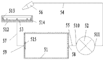
Fig. 6 is the structural representation of boring cooling device among Fig. 1.
Among the figure: horizontal boring machine-1, highwall-drilling machine-2, quick compactor-3, plug-in type locator-4, boring cooling device-5; Clamping fixture seat-6, datum level 7, cavity-8, horizontal base-11, horizontal base plate-12, motor one-13, shaft coupling one-14, bushing plate one-15, drill bit one-16, cylinder one-17, drill bushing one-18, gear reduction box one-19, line slideway-110, stand-21, swing seat-22, vertical base plate-23, motor two-24, shaft coupling two-25, bushing plate two-26, drill bit two-27, cylinder two-28, cylinder three-29, drill bushing two-210, gear reduction box two-211, line slideway two-212, pressure head-31, bearing-32, following locating piece-33, side locating piece-34, adjustable locating piece-35, pressure arm-36, guide pad-37, groove-38, compactor support-39, mounting blocks-310, projection one-311, projection two-312, projection three-313, toggle formula quick-speed jigs-314, adjustable location block-315, regulating block-316, adjustment screw-317, regulating block groove-318, locating notch-319, handle-320, support-41, alignment pin-42, pin tube-43, supporting base-44, latch-45, handle-46, pin-and-hole-47, handle slot-48, locating slot-49, transverse slat-410, support plate-411, base plate-412, column-413, installing plate-414, fagging-415;
Tank for coolant-51, coolant pump-52, collect at the bottom of box-53, woven hose-54, drain pipe-55, nozzle-56, liquid back pipe-57, liquid outlet-58, liquid return hole-59, import-510, outlet-511, the box-512, gusset-513, filter screen one-514, filter screen two-515.
The specific embodiment
Below in conjunction with shown in the accompanying drawing the utility model is described further.
As shown in Figure 1: a kind of weldering drill jig with rig comprises clamping fixture seat 6, horizontal boring machine 1, highwall-drilling machine 2, quick compactor 3, plug-in type locator 4, boring cooling device 5; Described clamping fixture seat is provided with datum level 7, cavity 8; Horizontal boring machine has two; Compactor has two fast; The plug-in type locator has two; Described horizontal boring machine comprises horizontal base 11, and described base is connected with the clamping fixture seat screw; Described highwall-drilling machine comprises stand 21, and described stand is connected with the clamping fixture seat screw; Described quick compactor comprises compactor support 39, and described compactor support is connected with the clamping fixture seat screw; Described plug-in type locator comprises base plate 412, and described base plate is connected with the clamping fixture seat screw; Described boring cooling device comprises tank for coolant 51, and described tank for coolant is connected with the clamping fixture seat screw in the cavity of clamping fixture seat.
As shown in Figure 2: horizontal boring machine also comprises horizontal base plate 12, line slideway 1; Line slideway one is connected with horizontal base, horizontal bottom plate screw respectively; The cylinder body one of cylinder 1 is connected with horizontal base screw, and expansion link one is connected with horizontal base thread; Described horizontal boring machine also comprises motor 1, shaft coupling 1, gear reduction box 1, bushing plate 1, drill bit 1; Motor one is connected with gear reduction box one by shaft coupling one; Bushing plate one is provided with drill bushing 1, and drill bushing one is adaptive with drill bit one; Drill bit one has two, and drill bit one passes drill bushing one and is connected with gear reduction box one; Motor one is connected with horizontal bottom plate screw; Gear reduction box one is connected with horizontal bottom plate screw; Described bushing plate one is fixedlyed connected with horizontal base.
As shown in Figure 3: highwall-drilling machine also comprises swing seat 22, vertical base plate 23, and is hinged between described stand and swing seat; Described highwall-drilling machine also comprises motor 2 24, shaft coupling 2 25, gear reduction box 2 211, bushing plate 2 26, drill bit 2 27; Described motor two is connected with gear reduction box two by shaft coupling two; Bushing plate two is provided with drill bushing 2 210, and drill bushing two is adaptive with drill bit two; Described drill bit two has two, and described drill bit two passes bushing plate two and is connected with gear reduction box two; Described motor two is connected with vertical bottom plate screw; Described gear reduction box two is connected with vertical bottom plate screw; Described bushing plate two is connected with swing seat screw; Line slideway 2 212 is connected with swing seat, vertical bottom plate screw respectively; The cylinder body two of cylinder 2 28 is connected with swing seat screw, and expansion link two is connected with vertical base thread; The cylinder body three of cylinder 3 29 is connected with the stand screw, and expansion link three is threaded with the swing seat.
As shown in Figure 4: quick compactor, comprise pressure head 31, toggle formula quick-speed jigs 314, described toggle formula quick-speed jigs comprises pressure arm 36, handle 320, described pressure head is connected with pressure arm front end screw; Described quick compactor also comprises bearing 32, following locating piece 33, side locating piece 34, adjustable locating piece 35; Described bearing also comprises mounting blocks 310; Described mounting blocks is provided with projection 1, projection 2 312, projection 3 313 successively, and projection three highly is higher than projection two, and projection two highly is higher than projection one; Described toggle formula quick-speed jigs is close to the projection two side faces and is connected with projection one end face screw; Described quick compactor also comprises guide pad 37, and described guide pad is provided with groove 38, and described recess width and pressure arm thickness are adaptive; Described guide pad is connected with projection three end face screws; Described side locating piece is connected with projection three side screws; Described locating piece down is connected with the end face screw of mounting blocks; Described adjustable locating piece comprises adjustable location block 315, regulating block 316, adjustment screw 317; Described adjustable location block is provided with regulating block groove 318, and the width and the regulating block of described regulating block groove are adaptive; Described adjustment screw is passed adjustable location block and is connected with regulating block; Described adjustable location block also is provided with locating notch 319, and described locating notch is the right angle excision, and direction is parallel with the regulating block groove.The end screw that the locating notch of described adjustable locating piece is close to mounting blocks connects; Described compactor support is connected with the other end screw of mounting blocks.
As shown in Figure 5: the plug-in type locator comprises support 41, alignment pin 42, pin tube 43, supporting base 44; Described supporting base comprises transverse slat 410, support plate 411, and described transverse slat becomes the T font to be connected with support plate, and described support plate length equates that with the pin tube thickness is less than pin tube external diameter; Described support plate and the welding of pin tube; Described alignment pin comprises latch 45, handle 46; Described pin tube is provided with the pin-and-hole 47 adaptive with latch: the length of described latch is longer than the length of pin tube; Described pin tube is axially arranged with handle slot 48; Described pin tube also is provided with locating slot 49, and described locating slot has two, becomes 90 degree to be communicated with respectively with two ends of handle slot; Described handle slot, locating slot penetrate into pin tube periphery from pin-and-hole; Described handle is cylindrical, and the width of described handle slot and locating slot is greater than the diameter of handle; Angle is the right angle between described handle and latch; Described handle passes handle slot and the welding of latch tail end; Described support also comprises column 413, installing plate 414, fagging 415; Described column lower end face and base plate welding; Described installing plate is shaped as rectangle, the lower surface welding of described column upper surface and installing plate; Described installing plate size is greater than the transverse slat of supporting base, and described transverse slat is connected with installing plate upper surface screw; The lower surface welding of described fagging one end and installing plate, the other end and column welding.
As shown in Figure 6: the boring cooling device also comprises coolant pump 52, collects box 53, woven hose 54, drain pipe 55, nozzle 56, liquid back pipe 57; Described tank for coolant is provided with liquid outlet 58, liquid return hole 59, and described coolant pump is provided with import 510, outlet 511; The liquid outlet of described tank for coolant is communicated with the import of coolant pump by drain pipe; Described woven hose is communicated with the cooling delivery side of pump; Described nozzle is communicated with woven hose; Described liquid back pipe one end is communicated with the liquid return hole of tank for coolant, and the other end is communicated with the collection box.Described collection box comprises at the bottom of the box 512, gusset 513; Described gusset and box back welding connect, and described collection box is provided with filter screen 1, and the mesh shape of described filter screen one is a rhombus, and the grid length of side is 1mm; Described filter screen one is connected with the gusset screw of collecting box; The liquid return hole place of described tank for coolant is provided with filter screen 2 515; The mesh shape of described filter screen two is a rhombus, and the grid length of side is 1mm; Described filter screen two is connected with the liquid return hole place screw of tank for coolant.
The weldering drill jig of band rig is according to the needs of automobile frame welding and boring, with horizontal boring machine, highwall-drilling machine, compactor, plug-in type locator, boring cooling device are combined into one compact conformation by certain quantity and status requirement and clamping fixture seat fast; Replace common apparatus with special planes such as horizontal boring machine, highwall-drilling machines, the body body is little, and is simple in structure, the efficient height, and drilling quality can guarantee; With the feed mechanism of cylinder as rig, make centripetal force adjustable and feeding is steady, withdraw from fast after the processing; Have bushing plate, can improve borehole accuracy; Be provided with wobble drive mechanism between the stand of highwall-drilling machine and swing seat, the swing seat that makes highwall-drilling machine together with motor two, shaft coupling two, reduction box two, bushing plate two, drill bit is second-class can not influence the convenient lifting of vehicle frame from vehicle frame top swing turn-off.With quick compactor the automobile frame location is compressed, efficient and convenient; Use toggle formula quick-speed jigs in quick compactor, make quick compactor simple in structure, easy to operate, the efficient height; The groove of guide pad blocks pressure arm, and pressure arm can not be rocked, and is more firm; Adjustable locating piece is regulated according to automobile frame location division actual size, compresses simple and reliable.The alignment pin of plug-in type locator cooperates with locating hole on the automobile frame, when satisfying automobile frame welding processing positioning requirements, has satisfied the positioning accuracy request of boring processing; The alignment pin of plug-in type locator be contained in that the pin tube is provided with the adaptive pin-and-hole of latch in, the pin tube is fixedlyed connected with supporting base; Supporting base is fixedlyed connected with support, makes alignment pin can keep accurate position, improves positioning accuracy and repetitive positioning accuracy, and convenient to operation.Described pin tube is provided with handle slot, two locating slots, and handle is in the operating position or withdraw from the position and can turn in the locating slot, to keep the alignment pin stable state.The cooling fluid of boring cooling device can repeat to reclaim use, do not influence environment, alleviate cleaning work amount, the good cooling results of workpiece; The nozzle of boring cooling device is concentrated cooling fluid and is cast in drill hole, has improved cooling effect, alleviates the cleaning work amount of workpiece, and has lubrication, has improved drilling life of bit; Collect box and reclaim cooling fluid and drilling cuttings, keep clean environment; Be provided with filter screen one, filter screen two can block drilling cuttings.Mesh shape is a rhombus, easily makes.The grid length of side is 1mm, and it is unimpeded and block drilling cuttings to take into account cooling fluid.
Claims (6)
1. the weldering drill jig with rig comprises clamping fixture seat, it is characterized in that: the weldering drill jig of described band rig also comprises horizontal boring machine (1), highwall-drilling machine (2), quick compactor (3), plug-in type locator (4), boring cooling device (5); Described highwall-drilling machine, horizontal boring machine are fixedlyed connected with clamping fixture seat; Described quick compactor, plug-in type locator are fixedlyed connected with clamping fixture seat; Described boring cooling device is fixedlyed connected with clamping fixture seat; Described clamping fixture seat (6) is provided with datum level (7), cavity (8).
2. the weldering drill jig of band rig according to claim 1 is characterized in that: described horizontal boring machine comprises horizontal base (11), horizontal base plate (12), is provided with guide rail one, feed mechanism one between described horizontal base, horizontal base plate; Described horizontal boring machine also comprises motor one (13), shaft coupling one (14), reduction box one, bushing plate one (15), drill bit one (16); Described motor one is connected with reduction box one by shaft coupling one; Described drill bit one passes bushing plate one and is connected with reduction box one; Described motor one is fixedlyed connected with horizontal base plate; Described reduction box one is fixedlyed connected with horizontal base plate; Described bushing plate one is fixedlyed connected with horizontal base; Described horizontal base is fixedlyed connected with clamping fixture seat.
3. the weldering drill jig of band rig according to claim 1 and 2 is characterized in that: described highwall-drilling machine comprises stand (21), swing seat (22), vertical base plate (23), and is hinged between described stand and swing seat; Be provided with guide rail two, feed mechanism two between described swing seat and vertical base plate; Described highwall-drilling machine also comprises motor two (24), shaft coupling two (25), reduction box two, bushing plate two (26), drill bit two (27); Described motor two is connected with reduction box two by shaft coupling two; Described drill bit two passes bushing plate two and is connected with reduction box two; Described motor two is fixedlyed connected with vertical base plate; Described reduction box two is fixedlyed connected with vertical base plate; Described bushing plate two is fixedlyed connected with the swing seat; Be provided with wobble drive mechanism between described stand and swing seat; Described stand is fixedlyed connected with clamping fixture seat.
4. the weldering drill jig of band rig according to claim 3, it is characterized in that: described quick compactor, comprise toggle formula quick-speed jigs (314), described toggle formula quick-speed jigs comprises pressure arm (36), handle (320), and described quick compactor also comprises pressure head (31), bearing (32), following locating piece (33), side locating piece (34), adjustable locating piece (35); Described pressure head is fixedlyed connected with pressure arm (36) front end; Described toggle formula quick-speed jigs is fixedlyed connected with bearing; Described locating piece, side locating piece, adjustable locating piece are down fixedlyed connected with bearing; Described bearing is fixedlyed connected with clamping fixture seat.
5. the weldering drill jig of band rig according to claim 4 is characterized in that: described plug-in type locator comprises support (41), alignment pin (42), pin tube (43), supporting base (44); Described pin tube is fixedlyed connected with supporting base; Described supporting base is fixedlyed connected with support; Described alignment pin comprises latch (45), handle (46); Described handle is fixedlyed connected with the latch tail end; Described pin tube is provided with the pin-and-hole adaptive with latch (47); The length of described latch is longer than the length of pin tube; Described support is fixedlyed connected with clamping fixture seat.
6. the weldering drill jig of band rig according to claim 5 is characterized in that: described boring cooling device comprises tank for coolant (51), coolant pump (52), collects box (53), woven hose (54), drain pipe (55), nozzle (56), liquid back pipe (57); Described tank for coolant is provided with liquid outlet (58), liquid return hole (59), and described coolant pump is provided with import (510), outlet (511); Described collection box comprises (512), gusset (513) at the bottom of the box, and described gusset is fixedlyed connected with at the bottom of the box; The liquid outlet of described tank for coolant is communicated with the import of coolant pump by drain pipe; Described woven hose is communicated with the cooling delivery side of pump; Described nozzle is communicated with woven hose; Described liquid back pipe one end is communicated with the liquid return hole of tank for coolant, and the other end is communicated with the collection box; Described tank for coolant is fixedlyed connected with clamping fixture seat in the cavity of clamping fixture seat.
?
Priority Applications (1)
| Application Number | Priority Date | Filing Date | Title |
|---|---|---|---|
| CN2010206843535U CN201997944U (en) | 2011-05-09 | 2011-05-09 | Welding and drilling clamp with drilling machines |
Applications Claiming Priority (1)
| Application Number | Priority Date | Filing Date | Title |
|---|---|---|---|
| CN2010206843535U CN201997944U (en) | 2011-05-09 | 2011-05-09 | Welding and drilling clamp with drilling machines |
Publications (1)
| Publication Number | Publication Date |
|---|---|
| CN201997944U true CN201997944U (en) | 2011-10-05 |
Family
ID=44700718
Family Applications (1)
| Application Number | Title | Priority Date | Filing Date |
|---|---|---|---|
| CN2010206843535U Expired - Fee Related CN201997944U (en) | 2011-05-09 | 2011-05-09 | Welding and drilling clamp with drilling machines |
Country Status (1)
| Country | Link |
|---|---|
| CN (1) | CN201997944U (en) |
Cited By (4)
| Publication number | Priority date | Publication date | Assignee | Title |
|---|---|---|---|---|
| CN102218661A (en) * | 2010-12-28 | 2011-10-19 | 上海英伦帝华汽车部件有限公司 | Welding and drilling clamp with driller |
| CN102941430A (en) * | 2012-12-18 | 2013-02-27 | 江西江铃底盘股份有限公司 | Quick assembling fixture for welding steel plate pedestal assembly |
| CN106271658A (en) * | 2016-09-18 | 2017-01-04 | 新乡学院 | A kind of fence automatic soldering device |
| CN106736575A (en) * | 2016-12-15 | 2017-05-31 | 江门市金力高锁业有限公司 | A kind of door handle automatic drilling, plus nail, welding processing equipment |
-
2011
- 2011-05-09 CN CN2010206843535U patent/CN201997944U/en not_active Expired - Fee Related
Cited By (6)
| Publication number | Priority date | Publication date | Assignee | Title |
|---|---|---|---|---|
| CN102218661A (en) * | 2010-12-28 | 2011-10-19 | 上海英伦帝华汽车部件有限公司 | Welding and drilling clamp with driller |
| CN102941430A (en) * | 2012-12-18 | 2013-02-27 | 江西江铃底盘股份有限公司 | Quick assembling fixture for welding steel plate pedestal assembly |
| CN102941430B (en) * | 2012-12-18 | 2014-10-01 | 江西江铃底盘股份有限公司 | Quick assembling fixture for welding steel plate pedestal assembly |
| CN106271658A (en) * | 2016-09-18 | 2017-01-04 | 新乡学院 | A kind of fence automatic soldering device |
| CN106271658B (en) * | 2016-09-18 | 2018-06-19 | 新乡学院 | A kind of fence automatic soldering device |
| CN106736575A (en) * | 2016-12-15 | 2017-05-31 | 江门市金力高锁业有限公司 | A kind of door handle automatic drilling, plus nail, welding processing equipment |
Similar Documents
| Publication | Publication Date | Title |
|---|---|---|
| CN111940788A (en) | Efficient high-accuracy drilling machine | |
| CN201997944U (en) | Welding and drilling clamp with drilling machines | |
| CN111230170A (en) | Radial drill of quick processing location | |
| CN112122641A (en) | Drilling machine capable of being positioned quickly for machine manufacturing | |
| CN102218661B (en) | Welding and drilling clamp with driller | |
| CN116423220A (en) | Efficient numerical control lathe with double machining stations | |
| CN213827106U (en) | Multi-station drilling machine | |
| CN210099010U (en) | Drilling machine for machining | |
| CN215545054U (en) | Drilling machine for quickly drilling side wall of oilless bearing | |
| CN214720674U (en) | Drilling machine capable of drilling inclined hole | |
| CN214816648U (en) | Automatic compressing and drilling device of numerical control machine tool | |
| CN212469862U (en) | Efficient high-accuracy drilling machine | |
| CN108788736B (en) | Tapping machine for permanent magnet motor processing production line | |
| CN210615173U (en) | Bench drilling machine | |
| CN113305319A (en) | Drilling machine convenient to drill holes on two sides of workpiece simultaneously | |
| CN220162841U (en) | Optical glass micro-drill bit drilling machine with adjustable operation table | |
| CN220901960U (en) | Perforating machine for steel pipe machining | |
| CN216858948U (en) | Oblique guide pillar hole processing tool | |
| CN221473629U (en) | Petroleum drill pipe thread milling groove auxiliary fixtures | |
| CN221675902U (en) | Vertical drilling machine for machining | |
| CN219598149U (en) | Drilling equipment for motorcycle parts | |
| CN219581768U (en) | Counter sinking device for cast tubular beams | |
| CN218746220U (en) | Machine tool machining positioning device | |
| CN221494315U (en) | Positioning tool for radial drilling machine drilling | |
| CN208147331U (en) | A kind of drilling and taping aggregate machine tool |
Legal Events
| Date | Code | Title | Description |
|---|---|---|---|
| C14 | Grant of patent or utility model | ||
| GR01 | Patent grant | ||
| C17 | Cessation of patent right | ||
| CF01 | Termination of patent right due to non-payment of annual fee |
Granted publication date: 20111005 Termination date: 20130509 |