CN201978962U - Closed steering knuckle extruding mould for double-action press - Google Patents
Closed steering knuckle extruding mould for double-action press Download PDFInfo
- Publication number
- CN201978962U CN201978962U CN 201020694588 CN201020694588U CN201978962U CN 201978962 U CN201978962 U CN 201978962U CN 201020694588 CN201020694588 CN 201020694588 CN 201020694588 U CN201020694588 U CN 201020694588U CN 201978962 U CN201978962 U CN 201978962U
- Authority
- CN
- China
- Prior art keywords
- mould
- cavity die
- punch
- knuckle
- die
- Prior art date
- Legal status (The legal status is an assumption and is not a legal conclusion. Google has not performed a legal analysis and makes no representation as to the accuracy of the status listed.)
- Expired - Fee Related
Links
Images
Abstract
The utility model discloses a closed steering knuckle extruding mould for a double-action press. The mould comprises an upper concave mould and a lower concave mould; a cavity for forming the outline of a steering knuckle is formed between the upper concave mould and the lower concave mould; the upper concave mould and the lower concave mould are connected with each other through a matching structure of a guide post and a guide sleeve; an upper concave mould pressing plate is arranged at the top of the upper concave mould; a convex mould pressing plate, a convex mould and an upper moulding plate are sequentially arranged at the top of the upper concave mould pressing plate upwardly; the convex mould pressing plate, the convex mould and the upper moulding plate are connected through a pull rod structure which is vertically arranged; punched notches I which are used for allowing the convex mould to move downwardly are arranged at the middle parts of the upper concave mould, the upper concave mould pressing plate and the convex mould pressing plate; a lower moulding plate is horizontally arranged on the bottom surface of the lower concave mould downwardly; a lower punching head structure consisting of a push rod and an ejector rod is arranged at the bottom of the lower moulding plate; and punched notches II which are communicated with each other are arranged at the middle parts of the lower concave mould and the lower moulding plate. The mould provided by the utility model can position a billet accurately and quickly; no flash is generated; raw materials are saved; and the following cleaning and machining time is effectively reduced.
Description
Technical field
The utility model relates to mould manufacturing industry, and particularly a kind of pair of dynamic compressor is with inaccessible formula extrusion molding knuckle mould.
Background technology
Automobile steering knuckle belongs to complicated branch class part, is the key components and parts on the automobile chassis.It is the supported cart body weight both, transmits steering moment again and bears front-wheel skidding moment.The quality of knuckle plays sizable effect to the safe handling of automobile, and therefore strict to its mechanical performance and contour structures, manufacture difficulty is big.The rapid growth of current car output, FMT constantly develops, and it is that core is selected rational mode of texturing that distinct issues show with the blank of refining.
The difficult point of this knuckle is that the most advanced and sophisticated position of branch fully is shaped, and adopts inaccessible formula extrusion molding then to possess good forming effect.If do not adopt inaccessible formula extrusion molding, but the shaping of general open die forging, impressing forging, then the overlap position has a large amount of waste materials to overflow and causes waste of material, and inaccessible formula is shaped and then can stock utilization is reached more than 95% by accurate blanking.
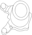
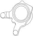
As depicted in figs. 1 and 2, use the knuckle forging of this mould manufacturing structurally to have following characteristics: 1. the part core is a cone boss with holes; 2. 4 sheet flanges are arranged, and thickness is 15mm; 3. the cross section is symmetrical substantially, but changes more violent; 4. boss one side has 2 shapes similar, the side leg that length is long.In addition, this knuckle dimensional accuracy (tolerance grade not noted ± 0.6mm, maximum dislocation 0.7mm), surface quality (surface does not allow lamination, lacks defectives such as material, crackle, corrosion) is strict.
Summary of the invention
In view of this, the purpose of this utility model provides a kind of pair of dynamic compressor with inaccessible formula extrusion molding knuckle mould, can be used in the extrusion molding of aforementioned knuckle, its accurate positioning, yield rate height.
The purpose of this utility model is achieved through the following technical solutions:
This pair dynamic compressor comprises upper cavity die and lower cavity die with inaccessible formula extrusion molding knuckle mould, and for being used to form the die cavity of knuckle exterior contour, the structure that cooperates by guide pillars and bushes between the described upper and lower die is connected between the described upper and lower die; The top, horizontal of described upper cavity die is provided with the upper cavity die pressing plate, the top of described upper cavity die pressing plate up is disposed with punch pad, punch and cope match-plate pattern, be connected by vertically disposed Tiebar structure between described punch pad, punch and the cope match-plate pattern, the middle part of described upper cavity die, upper cavity die pressing plate, punch pad offers and is used for the jet-bedding I that punch moves downward, the lower end of described punch and jet-bedding I are equipped with and with the form of upper punch blank are carried out Closed Extrusion, form the last endoporus of knuckle; The bottom surface of described lower cavity die has been horizontally disposed with lower bolster downwards, the bottom of described lower bolster is provided with the low punch structure of being made up of push rod and push rod, the middle part of described lower cavity die and lower bolster offers the jet-bedding II of perforation, described low punch structure and jet-bedding II are equipped with and with the form of low punch blank are carried out Closed Extrusion, form the following endoporus of knuckle.
Further, be provided with convex mould pad between described punch and the cope match-plate pattern;
Further, the cylindrical of described convex mould pad is arranged with the punch spacing collar;
Further, be provided with the die backing plate between described lower cavity die and the lower bolster, described jet-bedding II is by the die backing plate;
Further, described lower cavity die is arranged with lower cavity die centre circle and lower cavity die outer ring successively along its cylindrical, and described upper cavity die is arranged with upper cavity die centre circle and upper cavity die outer ring successively along its cylindrical;
Further, fix by screw and alignment pin between described upper cavity die outer ring and the upper cavity die pressing plate;
Further, described knuckle mould also comprises baroclinic block, and the cylindrical of described upper cavity die pressing plate is provided with the face of baroclining, and described baroclinic block is provided with the face of exerting pressure with the suitable shape of the face that baroclines, and the described face of exerting pressure cooperates with the face of baroclining and compresses;
Further, fix by screw between described lower bolster and the lower cavity die outer ring.
The beneficial effects of the utility model are:
(1) the blank accurate positioning is rapid: the blank external diameter that the utility model uses is identical with the lower cavity die aperture, blank is directly put into concave die cavity can accurately locate, overcome traditional open type or half-closed die forging blank can't or the inconvenience problem of accurately locating;
(2) the utility model adopts inaccessible formula Forging Technology to be shaped fully, after knuckle forging non-trimming, last lower cavity die are killed by baroclinic block, form the die cavity of a complete closed, thereby can not produce overlap, both save raw material, can reduce postorder cleaning and mach man-hour again;
(3) the upper and lower mould guiding does not accurately have offsetting, upper cavity die under the effect of pull bar, descending at punch with before blank does not also contact, the guide pillar guide pin bushing just freely imports accurate the guiding already, kill die again by baroclinic block and form near closed hollow ring, can not misplace thereby guarantee to go up lower cavity die;
(4) upward be equipped with reliable head part device for discharging in the lower cavity die, head part was reliable rapidly after shaping finished, and the stuck phenomenon in die of knuckle can not occur.
Other advantages of the present utility model, target and feature will be set forth to a certain extent in the following description, and to a certain extent, based on being conspicuous to those skilled in the art, perhaps can from practice of the present utility model, obtain instruction to investigating hereinafter.Target of the present utility model and other advantages can realize and obtain by following specification and claims.
Description of drawings
In order to make the purpose of this utility model, technical scheme and advantage clearer, below in conjunction with accompanying drawing the utility model is described in further detail, wherein:
Fig. 1 is the top structure schematic diagram of knuckle;
Fig. 2 is the polycrystalline substance schematic diagram of knuckle;
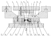
Fig. 3 is the perpendicular structural representation that cuts open of the present utility model.
The specific embodiment
Hereinafter with reference to accompanying drawing, preferred embodiment of the present utility model is described in detail.Should be appreciated that preferred embodiment only for the utility model is described, rather than in order to limit protection domain of the present utility model.
As shown in Figure 3, of the present utility model pair of dynamic compressor comprises upper cavity die 20 and lower cavity die 21 with inaccessible formula extrusion molding knuckle mould, for being used to form the die cavity of knuckle exterior contour, simultaneously, be connected with the structure that guide pin bushing 16 cooperates by guide pillar 15 between the upper and lower die between the upper and lower die; The top, horizontal of upper cavity die 20 is provided with upper cavity die pressing plate 7, the top of upper cavity die pressing plate 7 up is disposed with punch pad 6, punch 5 and cope match-plate pattern 2, be connected by vertically disposed Tiebar structure between punch pad 6, punch 5 and the cope match-plate pattern 2, the middle part of upper cavity die 20, upper cavity die pressing plate 7, punch pad 6 offers and is used for the jet-bedding I that punch 5 moves downward, the lower end of punch 5 and jet-bedding I are equipped with and with the form of upper punch blank are carried out Closed Extrusion, form the last endoporus of knuckle; The bottom surface of lower cavity die 21 has been horizontally disposed with lower bolster 24 and lower bolster 27 downwards successively, the bottom of lower bolster 27 is provided with the low punch structure of being made up of push rod 22 and push rod 23, the middle part of lower cavity die 21, lower bolster 24 and lower bolster 27 offers the jet-bedding II of perforation, low punch structure and jet-bedding II are equipped with and with the form of low punch blank are carried out Closed Extrusion, form the following endoporus of knuckle.
As further improvement, between punch 5 and cope match-plate pattern 2, be provided with convex mould pad 4, be arranged with the punch spacing collar at the cylindrical of convex mould pad 4, simultaneously, between lower cavity die 21 and lower bolster 27, be provided with die backing plate 24, jet-bedding II is by die backing plate 24.In mould, the area of convex mould pad 4 and convex mould pad 24 is big and certain thickness is arranged, and its role is to prevent that drift and die from directly affacting upper and lower template with power or the lathe table top causes distortion, extrudes pit.Add after such backing plate, the unit are active force of punch-die can be dropped to below the 400MPa.
As further improvement, lower cavity die 21 is arranged with lower cavity die centre circle 25 and lower cavity die outer ring 26 successively along its cylindrical, upper cavity die 20 is arranged with upper cavity die centre circle 19 and upper cavity die outer ring 17 successively along its cylindrical, in this way upper and lower die is carried out stationary positioned, avoids inconsistent phenomenon to take place.
As further improvement, the knuckle mould also comprises baroclinic block 9, as with the fit structure of baroclinic block, the cylindrical of upper cavity die pressing plate 7 is provided with the face of baroclining, and baroclinic block 9 is provided with and the face of exerting pressure that baroclines the suitable shape of face, matches with the face of baroclining by the face of exerting pressure, upper and lower die is imposed thrust, top at baroclinic block also is provided with the baroclinic block fixed head, avoids baroclinic block to shake, and influence compresses effect.
In the present embodiment, between upper cavity die outer ring 17 and upper cavity die pressing plate 7, fix by screw 14 and alignment pin 8, fixing by screw 18 between lower bolster 27 and lower cavity die outer ring 21.
In this mold, because the diameter of blank is identical with the lower cavity die internal diameter, naturally locate by die cavity so can directly be placed on blank in the lower cavity die 21, then baroclinic block 9 is under the effect of double action hydraulic press outer slide, tightly push down upper cavity die pressing plate 7, thereby push down the die cavity that upper and lower die forms sealing.In stroke, guide pillar 15 slips into and realizes the location in the guide pin bushing 16; After ram travel finished outside, inner slide drove punch 5 and continues descendingly, and punch 5 carries out Closed Extrusion with the form of upper punch to blank, and push rod 23 is with the form of low punch another endoporus that is shaped simultaneously, thereby finished the forming process of knuckle.After shaping finished, baroclinic block was unclamped in the backhaul of outer slide elder generation, and the while pull bar is fixed on the outer slide up, and it is up to drive upper cavity die 20, and guide pillars and bushes separates, and die cavity is opened, and last push rod 22 promotes push rod 23 and ejects workpiece, finishes a forming period.
In this mold, last lower cavity die and punch, push rod adopts 4Cr5MoSiV1(H13) hot die steel.This type of material is widely used, and has than higher calorific intensity and hardness and has good toughness, thermal fatigue property and certain wearability under mesophilic condition, is suitable as very much the material of the easy loss mould of inaccessible this molding mode of extruding.Simultaneously, its heat treatment deformation is little, and the oxide skin performance tendentiousness that produces during air quenching is little, and the erosion effect that can resist metal, satisfies the forging free from corrosion requirement in surface.
Explanation is at last, above embodiment is only unrestricted in order to the explanation the technical solution of the utility model, although the utility model is had been described in detail with reference to preferred embodiment, those of ordinary skill in the art is to be understood that, can make amendment or be equal to replacement the technical solution of the utility model, and not breaking away from the aim and the scope of the technical program, it all should be encompassed in the middle of the claim scope of the present utility model.
Claims (8)
1. two dynamic compressors are with inaccessible formula extrusion molding knuckle mould, it is characterized in that: described knuckle mould comprises upper cavity die and lower cavity die, for being used to form the die cavity of knuckle exterior contour, the structure that cooperates by guide pillars and bushes between the described upper and lower die is connected between the described upper and lower die; The top, horizontal of described upper cavity die is provided with the upper cavity die pressing plate, the top of described upper cavity die pressing plate up is disposed with punch pad, punch and cope match-plate pattern, be connected by vertically disposed Tiebar structure between described punch pad, punch and the cope match-plate pattern, the middle part of described upper cavity die, upper cavity die pressing plate, punch pad offers and is used for the jet-bedding I that punch moves downward, the lower end of described punch and jet-bedding I are equipped with and with the form of upper punch blank are carried out Closed Extrusion, form the last endoporus of knuckle; The bottom surface of described lower cavity die has been horizontally disposed with lower bolster downwards, the bottom of described lower bolster is provided with the low punch structure of being made up of push rod and push rod, the middle part of described lower cavity die and lower bolster offers the jet-bedding II of perforation, described low punch structure and jet-bedding II are equipped with and with the form of low punch blank are carried out Closed Extrusion, form the following endoporus of knuckle.。
2. pair dynamic compressor according to claim 1 is characterized in that: be provided with convex mould pad between described punch and the cope match-plate pattern with inaccessible formula extrusion molding knuckle mould.
3. pair dynamic compressor according to claim 2 is with inaccessible formula extrusion molding knuckle mould, and it is characterized in that: the cylindrical of described convex mould pad is arranged with the punch spacing collar.
4. pair dynamic compressor according to claim 1 is characterized in that with inaccessible formula extrusion molding knuckle mould: be provided with the die backing plate between described lower cavity die and the lower bolster, described jet-bedding II is by the die backing plate.
5. pair dynamic compressor according to claim 1 is with inaccessible formula extrusion molding knuckle mould, it is characterized in that: described lower cavity die is arranged with lower cavity die centre circle and lower cavity die outer ring successively along its cylindrical, and described upper cavity die is arranged with upper cavity die centre circle and upper cavity die outer ring successively along its cylindrical.
6. pair dynamic compressor according to claim 1 is characterized in that: fix by screw and alignment pin between described upper cavity die outer ring and the upper cavity die pressing plate with inaccessible formula extrusion molding knuckle mould.
7. pair dynamic compressor according to claim 1 is with inaccessible formula extrusion molding knuckle mould, it is characterized in that: described knuckle mould also comprises baroclinic block, the cylindrical of described upper cavity die pressing plate is provided with the face of baroclining, described baroclinic block is provided with the face of exerting pressure with the suitable shape of the face that baroclines, and the described face of exerting pressure cooperates with the face of baroclining and compresses.
8. pair dynamic compressor according to claim 1 is characterized in that: fix by screw between described lower bolster and the lower cavity die outer ring with inaccessible formula extrusion molding knuckle mould.
Priority Applications (1)
| Application Number | Priority Date | Filing Date | Title |
|---|---|---|---|
| CN 201020694588 CN201978962U (en) | 2010-12-31 | 2010-12-31 | Closed steering knuckle extruding mould for double-action press |
Applications Claiming Priority (1)
| Application Number | Priority Date | Filing Date | Title |
|---|---|---|---|
| CN 201020694588 CN201978962U (en) | 2010-12-31 | 2010-12-31 | Closed steering knuckle extruding mould for double-action press |
Publications (1)
| Publication Number | Publication Date |
|---|---|
| CN201978962U true CN201978962U (en) | 2011-09-21 |
Family
ID=44606430
Family Applications (1)
| Application Number | Title | Priority Date | Filing Date |
|---|---|---|---|
| CN 201020694588 Expired - Fee Related CN201978962U (en) | 2010-12-31 | 2010-12-31 | Closed steering knuckle extruding mould for double-action press |
Country Status (1)
| Country | Link |
|---|---|
| CN (1) | CN201978962U (en) |
Cited By (5)
| Publication number | Priority date | Publication date | Assignee | Title |
|---|---|---|---|---|
| CN104439010A (en) * | 2014-12-13 | 2015-03-25 | 遵义金惠机械制造有限责任公司 | Detachable female-die rigid clamping device |
| CN106825098A (en) * | 2017-01-07 | 2017-06-13 | 中北大学 | A kind of differential-velocity extrusion shaping dies of magnesium alloy high-performance cup shell |
| CN107774858A (en) * | 2016-08-30 | 2018-03-09 | 衡水市潴龙万向有限公司 | A kind of automobile steering joint closed die forging technique |
| CN112828217A (en) * | 2020-11-18 | 2021-05-25 | 重庆电子工程职业学院 | Material increase regulation and control method for reducing sinking depth of electric upsetting end face to improve mixed crystals |
| CN114247814A (en) * | 2021-12-23 | 2022-03-29 | 湖南顶立科技有限公司 | Extrusion forming device and die pressing method |
-
2010
- 2010-12-31 CN CN 201020694588 patent/CN201978962U/en not_active Expired - Fee Related
Cited By (9)
| Publication number | Priority date | Publication date | Assignee | Title |
|---|---|---|---|---|
| CN104439010A (en) * | 2014-12-13 | 2015-03-25 | 遵义金惠机械制造有限责任公司 | Detachable female-die rigid clamping device |
| CN104439010B (en) * | 2014-12-13 | 2017-01-25 | 遵义金惠机械制造有限责任公司 | Detachable female-die rigid clamping device |
| CN107774858A (en) * | 2016-08-30 | 2018-03-09 | 衡水市潴龙万向有限公司 | A kind of automobile steering joint closed die forging technique |
| CN106825098A (en) * | 2017-01-07 | 2017-06-13 | 中北大学 | A kind of differential-velocity extrusion shaping dies of magnesium alloy high-performance cup shell |
| CN106825098B (en) * | 2017-01-07 | 2018-09-18 | 中北大学 | A kind of differential-velocity extrusion shaping dies of magnesium alloy high-performance cup shell |
| CN112828217A (en) * | 2020-11-18 | 2021-05-25 | 重庆电子工程职业学院 | Material increase regulation and control method for reducing sinking depth of electric upsetting end face to improve mixed crystals |
| CN112828217B (en) * | 2020-11-18 | 2022-08-30 | 重庆电子工程职业学院 | Material increase regulation and control method for reducing sinking depth of electric upsetting end face to improve mixed crystals |
| CN114247814A (en) * | 2021-12-23 | 2022-03-29 | 湖南顶立科技有限公司 | Extrusion forming device and die pressing method |
| CN114247814B (en) * | 2021-12-23 | 2023-12-05 | 湖南顶立科技有限公司 | Extrusion molding device and molding method |
Similar Documents
| Publication | Publication Date | Title |
|---|---|---|
| CN203304399U (en) | Horn basin stand stamping progressive die | |
| CN201978962U (en) | Closed steering knuckle extruding mould for double-action press | |
| CN102319808B (en) | Hot stamping mould for nut | |
| CN108213295B (en) | Ozzle forging method and nuclear power main pump pump case profiling forging technology | |
| CN103191945A (en) | Method and device for high-pressure hydraulic flange plasticity forming | |
| CN203900355U (en) | Combined die for precise forging production of camshaft gear blanks | |
| CN201012375Y (en) | Eyelet punching flanging composite mold | |
| CN203265502U (en) | Hot forging device for transmission shaft joint fork with horizontal fork part | |
| CN103121075A (en) | Hot forging method for transmission shaft yoke with horizontal yoke part | |
| CN203304417U (en) | Flip-over type piercing and blanking die | |
| CN204449176U (en) | A kind of block forging mould for cross axle Warm Extrusion | |
| CN109482739A (en) | Formed punch blank holder integrated mould | |
| CN204974783U (en) | Wheel nut multistation extrusion die | |
| CN202123158U (en) | Special die for shaping lower supporting seat orifices of automobile shock absorber | |
| CN103736896A (en) | Die floating type forging die rack | |
| CN206122374U (en) | Floating plug extrusion die structure of ring gear | |
| CN110479938A (en) | The forging and molding mold and manufacturing process of flanged ball valve forging | |
| CN103624151A (en) | Novel progressive die | |
| CN109261802A (en) | A kind of mold and processing method of the stamping flange of rolled plate | |
| CN204638892U (en) | The drawing die of cylindrical shape sheet metal component | |
| CN209110000U (en) | A kind of mold of the stamping flange of rolled plate | |
| CN209318684U (en) | A kind of seamless steel pipe local contraction formed automobile axle tube hot-extrusion mold | |
| CN208495510U (en) | A kind of mold with inside and outside clip | |
| CN202803937U (en) | Novel progressive die | |
| CN102886477A (en) | Ball core closed-die forging process using valve body ball core forging die |
Legal Events
| Date | Code | Title | Description |
|---|---|---|---|
| C14 | Grant of patent or utility model | ||
| GR01 | Patent grant | ||
| C17 | Cessation of patent right | ||
| CF01 | Termination of patent right due to non-payment of annual fee |
Granted publication date: 20110921 Termination date: 20111231 |