CN201963278U - Oil well casing pipe gas pressurized and recycling device - Google Patents
Oil well casing pipe gas pressurized and recycling device Download PDFInfo
- Publication number
- CN201963278U CN201963278U CN2011200385256U CN201120038525U CN201963278U CN 201963278 U CN201963278 U CN 201963278U CN 2011200385256 U CN2011200385256 U CN 2011200385256U CN 201120038525 U CN201120038525 U CN 201120038525U CN 201963278 U CN201963278 U CN 201963278U
- Authority
- CN
- China
- Prior art keywords
- gas
- pressure
- pipeline
- casing
- casing pipe
- Prior art date
- Legal status (The legal status is an assumption and is not a legal conclusion. Google has not performed a legal analysis and makes no representation as to the accuracy of the status listed.)
- Expired - Lifetime
Links
Images
Abstract
An oil well casing pipe gas pressurized and recycling device is use for recycling the oil well casing pipe gas of oil fields. An oil pipe of a Christmas tree well head is connected with a constant pressure air evacuation valve. An air inlet of the constant pressure air evacuation valve is connected with a high pressure hose. The other end of the high pressure hose is connected with a gas booster pump outlet pipe which is connected with an outlet of the gas booster pump. A three-way connecting pipeline is arranged on the gas booster pump outlet pipe. The other end of the three-way connecting pipeline is connected with the outlet of a check valve. The inlet of the check valve is connected with a gas flow meter through the pipeline. The inlet pipeline of the gas flow meter is provided with a pressure gauge. The inlet pipeline of the gas flow meter is connected with a casing pipe joint. An inlet pipe of the gas booster pump is connected with the pipeline between the gas flow meter and the check valve through the three-way pipeline. The oil well casing pipe gas pressurized and recycling device has the advantages that when the pressure of the oil well casing pipe is higher than the oil pipe back pressure, the oil well casing pipe gas pressurized and recycling device can pressurize and recycle the casing pipe gas, thereby achieving the purpose of improving pump efficiency and crude oil output. When the pressure of the casing pipe is lower than the back pressure, the low pressure casing pipe gas is pressurized to a state of being larger than the oil well back pressure, thereby being capable of recycling the casing pipe gas.
Description
Technical field
The utility model relates to oil recovery technique field, oil field.Being particularly related to the recovery isolated plant of a kind of well casing gas in the oil recovery process, is a kind of well casing gas boosting recovery device.
Background technology
Well casing gas is as the retail natural gas resource of association in the oil well production process, and along with the natural depletion of oil-well strata energy, casing pressure progressively reduces.Casing pressure is lower than the back pressure of oil well main line and can't enters production trunk line automatically.But in a single day sleeve pipe gas build the pressure, and gas is invaded oil well pump, will cause the oil well underproduction.Therefore, generally adopt method, lower the pressure in the sleeve pipe empty exclusion sleeve gas.Caused sleeve pipe gas contaminated environment thus, the oil recovery well site is inflammable and explosive and the serious waste of natural gas resource.If will reclaim after the supercharging of low-tension bushing gas, and be used for gas for domestic use and natural gas power, not only have tangible economic benefit, reach energy-saving and emission-reduction, have good comprehensive social benefit.
At present, the method for domestic recovery low-tension bushing gas mainly contains two kinds.The one, cylinder is installed on oil pumper or the production tree, utilize the reciprocating motion of oil pumper walking beam or polished rod, the interlock cylinder piston moves back and forth, and reaches the purpose of supercharging sleeve pipe gas.But the interlock mode exists installation cost height, construction to get angry and employs engineering truck and running the time influences the drawback of the safe operation of oil pumper like this, even the accident of oil pumper " overturning " occurs.The 2nd, adopt vehicle-mounted compressor unit, the method for mobile recovery of casing gas.Two problems of main existence during this method is used: mainly be impossible reclaim each casing gas simultaneously; Secondly, it is low that rate is implemented in manpower and freight height and measure, can not produce the scale economic benefit.
The utility model content
The purpose of this utility model is: a kind of well casing gas boosting recovery device is provided, adopts the rely on oneself method of supercharging of sleeve pipe gas, reach the purpose of supercharging recovery of casing gas.
The technical solution adopted in the utility model is: the well casing gas boosting recovery device, mainly form by valve discharging gas under certain pressure, high-pressure hose, casing joint, pressure meter, gas flowmeter, one way valve and gas booster pump, it is characterized in that: production tree well head petroleum pipeline connects valve discharging gas under certain pressure, valve discharging gas under certain pressure set casing pressure under reasonable casing pressure in petroleum pipeline exclusion sleeve gas, and stop the crude oil of petroleum pipeline inside to flow backwards.The air inlet port of valve discharging gas under certain pressure connects high-pressure hose; The other end of high-pressure hose connects the gas boosting pump discharge pipe, and the gas boosting pump discharge pipe connects the gas boosting delivery side of pump; On the gas boosting pump discharge pipe threeway is arranged, be connected with pipeline by threeway, the other end of pipeline connects the outlet of one way valve, the inlet of one way valve has pipeline to connect the gas flowmeter outlet, be connected with pressure meter on the gas flowmeter suction line, the variation of pressure meter energy monitoring sleeve pressure, the variation of flow meter energy monitoring sleeve gas instantaneous delivery; The suction line of gas flowmeter is connected with casing joint; On the pipeline between gas flowmeter and the one way valve threeway is arranged, be connected with gas boosting pump inlet pipe by threeway, gas boosting pump inlet pipe is connected with the gas boosting pump inlet.One way valve and pneumatic booster pump parallel connection, when preventing that casing pressure is higher than back pressure suddenly, the throttling of gas boosting pump and the sleeve pipe that the produces phenomenon that builds the pressure takes place, and prevents that the sleeve pipe gas after the supercharging from returning in the sleeve pipe.Pneumatic booster pump is to rely on the sleeve pipe atmospheric pressure as driving pressure.Gas boosting pump and valve discharging gas under certain pressure are existing products, and city's field energy is purchased.
In order to protect boosting recovery device not to be subjected to the influence of wild environment.Be welded with airtight casing, casing is welded in the casing joint, and pressure meter, gas flowmeter, one way valve, gas boosting pump discharge pipe, gas boosting pump inlet pipe and gas booster pump are arranged in the casing.
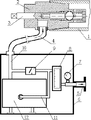
The operating principle of summary well casing gas boosting recovery device: consult Fig. 1.Casing joint 5 is connected with the casing of oil-pumping well outlet of producing; The end of petroleum pipeline 1 connects a valve discharging gas under certain pressure 2, and rotation vent valve pressure regulation bar 3 is also adjusted the pressure of the emission gases of valve discharging gas under certain pressure 2.When oil well casing pressure was higher than the pressure of setting, sleeve pipe gas directly entered valve discharging gas under certain pressure 2 by ball-and-seat 9 and venting high-pressure rubber pipe 4, and is discharged in the petroleum pipeline 1 according to the pressure of setting by valve discharging gas under certain pressure 2.When casing pressure during less than oil pipe back pressure (pressure of setting), gas enters pneumatic booster pump 12 after by gas flowmeter 8, when gas boosting pump 12 is pressurized to air pressure greater than the oil pipe back pressure, gas enters valve discharging gas under certain pressure 2 again, enter measuring station by oil well petroleum pipeline 1 then, reach the purpose of recovery.
The beneficial effects of the utility model: the utility model well casing gas boosting recovery device, when oil well casing pressure was higher than the oil pipe back pressure, energy level pressure recovery of casing gas reached the purpose that improves pump efficiency and crude output; When casing pressure is lower than back pressure, low-tension bushing gas is pressurized to greater than the Oil Well Back Pressure state, also can recovery of casing gas.
Description of drawings
Fig. 1 is the utility model well casing gas boosting recovery device structural profile schematic diagram.
Among the figure, the 1-petroleum pipeline; The 2-valve discharging gas under certain pressure; 3-vent valve pressure regulation bar; The 4-high-pressure hose; The 5-casing joint; The 6-casing; The 7-pressure meter; The 8-gas flowmeter; The 9-one way valve; 10-gas boosting pump discharge pipe; 11-gas boosting pump inlet pipe; 12-gas boosting pump.
The specific embodiment
Embodiment 1: with a well casing gas boosting recovery device is example, and the utility model is described in further detail.
Consult Fig. 1.The utility model well casing gas boosting recovery device mainly is made up of valve discharging gas under certain pressure 2, high-pressure hose 4, casing joint 5, casing 6, pressure meter 7, gas flowmeter 8, one way valve 9 and gas booster pump 12.
The end of production tree well head petroleum pipeline 1 connects a valve discharging gas under certain pressure 2.The air inlet port of valve discharging gas under certain pressure 2 connects a high-pressure hose 4.The other end of high-pressure hose 4 connects gas boosting pump discharge pipe 10.Gas boosting pump discharge pipe 10 connects the outlet of gas boosting pump 12; A threeway is arranged on the gas boosting pump discharge pipe 10, be connected with a pipeline by this threeway, the other end of pipeline connects the outlet of one way valve 9, and the inlet of one way valve 9 has pipeline to connect gas flowmeter 8 outlets.Be connected with pressure meter 7 on gas flowmeter 8 suction lines.The suction line of gas flowmeter 8 is connected with casing joint 5.A threeway is arranged on the pipeline between gas flowmeter 8 and the one way valve 9, be connected with gas boosting pump inlet pipe 11 by this threeway, gas boosting pump inlet pipe 11 is connected with 12 imports of gas boosting pump.
Be welded with an airtight casing 6, casing 6 is welded in the casing joint 5.Pressure meter 7, gas flowmeter 8, one way valve 9, gas boosting pump discharge pipe 10, gas boosting pump inlet pipe 11 and gas booster pump 12 are in casing 6.
Claims (2)
1. well casing gas boosting recovery device, mainly form by valve discharging gas under certain pressure (2), high-pressure hose (4), casing joint (5), pressure meter (7), gas flowmeter (8), one way valve (9) and gas booster pump (12), it is characterized in that: production tree well head petroleum pipeline (1) connects valve discharging gas under certain pressure (2), and the air inlet port of valve discharging gas under certain pressure (2) connects high-pressure hose (4); The other end of high-pressure hose (4) connects gas boosting pump discharge pipe (10), and gas boosting pump discharge pipe (10) connects the outlet of gas boosting pump (12); The gas boosting pump discharge pipe has threeway on (10), be connected with pipeline by threeway, the other end of pipeline connects the outlet of one way valve (9), and the inlet of one way valve (9) has pipeline to connect gas flowmeter (8) outlet, is connected with pressure meter (7) on gas flowmeter (8) suction line; The suction line of gas flowmeter (8) is connected with casing joint (5); On the pipeline between gas flowmeter (8) and the one way valve (9) threeway is arranged, be connected with gas boosting pump inlet pipe (11) by threeway, gas boosting pump inlet pipe (11) is connected with gas boosting pump (12) import.
2. well casing gas boosting recovery device according to claim 1, it is characterized in that: be welded with airtight casing (6), casing (6) is welded in the casing joint (5), and pressure meter (7), gas flowmeter (8), one way valve (9), gas boosting pump discharge pipe (10), gas boosting pump inlet pipe (11) and gas booster pump (12) are arranged in the casing (6).
Priority Applications (1)
| Application Number | Priority Date | Filing Date | Title |
|---|---|---|---|
| CN2011200385256U CN201963278U (en) | 2011-02-14 | 2011-02-14 | Oil well casing pipe gas pressurized and recycling device |
Applications Claiming Priority (1)
| Application Number | Priority Date | Filing Date | Title |
|---|---|---|---|
| CN2011200385256U CN201963278U (en) | 2011-02-14 | 2011-02-14 | Oil well casing pipe gas pressurized and recycling device |
Publications (1)
| Publication Number | Publication Date |
|---|---|
| CN201963278U true CN201963278U (en) | 2011-09-07 |
Family
ID=44525813
Family Applications (1)
| Application Number | Title | Priority Date | Filing Date |
|---|---|---|---|
| CN2011200385256U Expired - Lifetime CN201963278U (en) | 2011-02-14 | 2011-02-14 | Oil well casing pipe gas pressurized and recycling device |
Country Status (1)
| Country | Link |
|---|---|
| CN (1) | CN201963278U (en) |
Cited By (1)
| Publication number | Priority date | Publication date | Assignee | Title |
|---|---|---|---|---|
| CN107916912A (en) * | 2017-11-15 | 2018-04-17 | 长沙宁湖机械设备有限公司 | A kind of natural gas recovery device for oil well |
-
2011
- 2011-02-14 CN CN2011200385256U patent/CN201963278U/en not_active Expired - Lifetime
Cited By (2)
| Publication number | Priority date | Publication date | Assignee | Title |
|---|---|---|---|---|
| CN107916912A (en) * | 2017-11-15 | 2018-04-17 | 长沙宁湖机械设备有限公司 | A kind of natural gas recovery device for oil well |
| CN107916912B (en) * | 2017-11-15 | 2019-12-10 | 洋浦宇顺航空燃料有限公司 | Oil well natural gas recovery device |
Similar Documents
| Publication | Publication Date | Title |
|---|---|---|
| CN202064905U (en) | Gas lifting and liquid discharging device for vehicle natural gas compressor | |
| CN205137057U (en) | Turbocharging system | |
| CN108019190B (en) | Full-closed mixed transportation depressurization circulating gas lift system | |
| CN201614927U (en) | Pressurized deflating oil-extraction combining device linked with polished rod | |
| CN104405343A (en) | Recovery device for cluster well group associated gas and recovery method thereof | |
| CN102426084A (en) | Non-metal pipeline hydraulic pressure seepage verifying attachment | |
| CN205370896U (en) | Automobile repair workshop is with self -control air compressor machine station | |
| CN201963278U (en) | Oil well casing pipe gas pressurized and recycling device | |
| CN204312030U (en) | A kind of for collecting well group associated gas recovery device | |
| CN103822091A (en) | Natural gas recycling method for compressed natural gas stations | |
| CN202228028U (en) | Downhole bailing device in oil field | |
| CN202362121U (en) | Non-metal pipeline hydraulic pressure leakage inspection device | |
| CN202609903U (en) | Sulfuric acid pressure conveying system | |
| CN103821687A (en) | Air-liquid pump | |
| CN203683073U (en) | Containerized filling station | |
| CN202814805U (en) | Concrete pipe inner water pressure vertical type detection device | |
| CN207245680U (en) | Removable oil gas field well head recycling gas integral device | |
| CN105298949B (en) | A kind of portable gas supercharging device | |
| CN104179657A (en) | Passive pneumatic pressurizing device for underground coal mine | |
| CN202834758U (en) | Natural gas integrated standard station equipment | |
| CN204008315U (en) | A kind of skid-mounted type pipeline water filling pressure testing pumping plant | |
| CN204187267U (en) | A kind of hydraulic pressure aerating type bundled tube shipping container | |
| CN207599334U (en) | A kind of gas recovery system and device | |
| CN203476356U (en) | Portable single hydraulic prop type liquid supply device | |
| CN201763363U (en) | Portable pneumatic emulsion pump station |
Legal Events
| Date | Code | Title | Description |
|---|---|---|---|
| C14 | Grant of patent or utility model | ||
| GR01 | Patent grant | ||
| CX01 | Expiry of patent term | ||
| CX01 | Expiry of patent term |
Granted publication date: 20110907 |