CN201950461U - Automatic forming machine for metal fan impeller - Google Patents
Automatic forming machine for metal fan impeller Download PDFInfo
- Publication number
- CN201950461U CN201950461U CN2010206063247U CN201020606324U CN201950461U CN 201950461 U CN201950461 U CN 201950461U CN 2010206063247 U CN2010206063247 U CN 2010206063247U CN 201020606324 U CN201020606324 U CN 201020606324U CN 201950461 U CN201950461 U CN 201950461U
- Authority
- CN
- China
- Prior art keywords
- roll riveting
- blade
- installing rack
- roll
- impeller
- Prior art date
- Legal status (The legal status is an assumption and is not a legal conclusion. Google has not performed a legal analysis and makes no representation as to the accuracy of the status listed.)
- Expired - Lifetime
Links
Images


Landscapes
- Pinball Game Machines (AREA)
Abstract
The utility model relates to an automatic processing equipment for metal fan impellers, in particular to an automatic forming machine for metal fan impellers, which comprises a frame and a blade moulding mechanism, a blade cutting mechanism, a blade penetrating mechanism, a blade inserting mechanism, a middle disk division mechanism and an impeller rivet-rolling mechanism. The blade moulding mechanism, the blade cutting mechanism, the blade penetrating mechanism, the blade inserting mechanism, the middle disk division mechanism and the impeller rivet-rolling mechanism are arranged on the frame. The automatic forming machine for metal fan impellers has the advantages of novel structure, high automation degree and low production cost and reject rate. Meanwhile, the produced metal fan impeller is high in quality.
Description
Technical field
The utility model relates to a kind of automatic processing device of metal axial-flow fan impeller.
Background technology
The manufacturing process of existing metal axial-flow fan impeller is as follows: with raw metal punching out metal blade and cut-out on request into strips, be inserted into by hand in the sheet mid-game of circle with even slotted eye, put into mandrel then, again mid-game is split up into corresponding equidistant position by hand by technological requirement, utilize lathe or special-purpose riveting equipment, the mid-game outer rim is pushed with the roll riveting cutter, make closely fixing riveting molding of mid-game and blade, the impeller after at last moulding being finished takes out by hand.Adopt the defective of the metal axial-flow fan impeller existence that has production technology and device fabrication now as follows: 1: blade needs manual punching press or roll extrusion, and is cut to the blade of length unanimity; 2: must be with the qualified blade of forming, utilize manual the insertion in the corresponding groove of mid-game, carry out pre-assembled, this procedure takies a large amount of artificial; 3: during the roll extrusion built-up impeller, impeller must be penetrated in the roll riveting mandrel, because the flexible distortion of major axis, the impeller circular runout after the riveted joint is big, after general minor diameter impeller roll riveting finishes, no longer carries out dynamic balancing, and complete machine is subjected to the influence of impeller bigger, shake can occur; 4: the impeller after machining, must load and unload by hand, influence production efficiency.
In sum, adopt existing production technology and device fabrication metal axial-flow impeller to have that production efficiency is low, cost is high, the problem that product quality can not get ensureing.
Summary of the invention
Goal of the invention of the present utility model is the defective that exists in the above-mentioned existing metal axial-flow fan impeller production process in order to solve, and discloses a kind of working (machining) efficiency height, and the axiality of product is good, the metal axial-flow fan impeller automatic moulding machine that percent defective is low.
The utility model has adopted following technical scheme for achieving the above object:
A kind of metal blast fan automatic moulding machine comprises that frame and blade forming mechanism, blade shut-off mechanism, blade mounted thereto wear sheet mechanism, impeller inserted sheet mechanism, mid-game and divide disc mechanism and impeller roll riveting mechanism;
Blade forming mechanism comprises base plate, blade forming installing rack, stepper motor, organizes the roll extrusion wheels more and organizes hold-down devices more; Base plate in the blade forming mechanism is fixedly mounted on the frame, the blade forming installing rack is fixed on the base plate, many group roll extrusion wheels horizontally are installed on the blade forming installing rack, and hold-down devices is continuous with the roll extrusion wheels and quantity is corresponding, and hold-down devices is arranged on the blade forming installing rack;
The blade shut-off mechanism comprises shearing device, material casting device and base plate, and shearing device and material casting device all are installed on the frame by base plate;
Blade is worn sheet mechanism, comprises servomotor, gear-box, installing rack and organizes the merry-go-round type bunker device more; Servomotor links to each other with gear-box, and the merry-go-round type bunker device is installed on the installing rack, and gear-box links to each other with the merry-go-round type bunker device, and installing rack is fixed on the frame;
Impeller inserted sheet mechanism comprises inserted sheet cylinder, preceding mount pad, back mount pad, slide plate, guide pillar, many push rods and inlays cover; Preceding mount pad links to each other by guide pillar with the back mount pad, and slide plate is socketed on the guide pillar, and inserted sheet cylinder output links to each other with slide plate; The rear end of push rod is fixed on the tail skid, the edge cover before front end passes on the mount pad;
Mid-game divides disc mechanism, comprises branch dish cylinder, retainer cylinder, material supporting rack, material bearing shelf, many mid-game position-limited racks, impeller carriage, branch dish machine installing rack and pallet installing racks; Divide dish machine installing rack and pallet installing rack to be installed on the frame, the mid-game position-limited rack is arranged on the branch dish machine installing rack, and branch dish cylinder connects the mid-game position-limited rack; The retainer cylinder links to each other with material supporting rack, and the impeller carriage is installed in the top of material supporting rack, and the position of impeller carriage is corresponding with branch dish machine installing rack, and impeller carriage and material supporting rack are eccentric to be provided with, and material bearing shelf is fixed on the pallet installing rack;
Impeller roll riveting mechanism, comprise roll riveting base plate, roll riveting frame, last roll riveting device, following roll riveting device and bottom roller separator, the roll riveting base plate is fixedly mounted on the frame, the roll riveting frame is fixed on the roll riveting base plate, last roll riveting device is installed on the roll riveting frame, and following roll riveting device is arranged on the roll riveting base plate, and following roll riveting device comprises a plurality of rolling wheels down, last roll riveting device and following rolling wheel cooperate corresponding, and a following rolling wheel of following roll riveting device links to each other with the bottom roller separator.
As preferably, described blade forming mechanism also comprises motor installing rack, shaft coupling, idle wheel group, left limit post, right limit post, lack material shuts down inductive switch and adjuster; The motor installing rack that stepper motor is installed is on frame, and stepper motor links to each other with the roll extrusion wheels by shaft coupling; The left limit post is arranged on the outside of the roll extrusion wheels of high order end, the outside of the roll extrusion wheels that are arranged on low order end of right limit post; The position of adjuster is in the outside of right limit post, and adjuster is fixed on the blade forming installing rack by proofreading and correct installing plate; Lack material and shut down the outside that the position of inductive switch is in the left limit post.Further, described every group of roll extrusion wheels are taken turns and are constituted with the shaping cam of the band arc plush copper of its coupling by the moulding of band arc groove is recessed, divide two rows to be installed in the blade forming installing rack, to be that moulding is recessed take turns last row, following row is a shaping cam, wherein row's shaping cam directly is connected with blade forming installing rack mount down, and last row's moulding is recessed to be taken turns in the groove that is loaded on the blade forming installing rack; Adjacent roll extrusion wheels all connect by the idle wheel group, and the idle wheel group all is between two shaping cams of adjacent roll extrusion wheels, shaping cam on the roll extrusion wheels of low order end connects stepper motor by shaft coupling, and recessed the wheel with the shaping cam direction of rotation of moulding deviated from mutually; Described hold-down devices by pressure adjustment dish, compression press spring, suppress plate, depression bar, slide block, screw rod and adjustment cushion block and connect and compose; Compression press spring is contained in pressure adjustment dish and suppresses between the plate, the fixedly connected plate that suppresses in depression bar upper end, the lower end connects slide block, adjust cushion block be arranged on slider bottom and position be in moulding recessed take turns and shaping cam between the junction, the recessed wheel by slide block of moulding is loaded in the groove of blade forming installing rack; Adjuster is made of adjuster base plate, two row's adjuster side plates and correction roller, and two row's adjuster side plates are installed in parallel on the adjuster base plate, proofread and correct roller and are on the two adjuster base plates of arranging between the adjuster side plates.
As preferably, described blade shut-off mechanism also comprises guide rail and correcting plate, and shearing device and material casting device are respectively horizontal two groups; Guide rail is installed on the base plate, and wherein one group of shearing device is movably arranged on the guide rail.
As preferably, described shearing device comprises and cuts off die, movable punch and cut-out cylinder that movable punch is connected with the output that cuts off cylinder, on the cut-out die the fixedly die edge of a knife is set; Guide rail and base plate are provided for discharging the relief hole of waste material; The material casting device is made of material casting motor, driving gear set, protruding material casting wheel and recessed material casting wheel, the action of material casting driven by motor driving gear set, protruding material casting wheel all links to each other with driving gear set and synchronization action with recessed material casting wheel, and protruding material casting wheel and recessed material casting wheel cooperate corresponding up and down, and protruding material casting wheel deviates from mutually with recessed material casting wheel direction of rotation; The correcting plate is installed in the blade equipped at outlet port of the material casting device in the outside, on the correcting plate guiding groove is set, and the position of guiding groove is corresponding with the blade delivery outlet of material casting device.
As preferably, described merry-go-round type bunker device is two groups that are arranged in parallel, and is symmetrical arranged along the central plate of installing rack; Described merry-go-round type bunker device comprises feed bin fixed mount, bearing material storehouse, rotary cylinder and ratchet; The bearing material storehouse is installed on the installing rack by the feed bin fixed mount, and ratchet is arranged between bearing material storehouse and the feed bin fixed mount, and rotary cylinder links to each other with the bearing material storehouse, and what circular array was set in the bearing material storehouse is used to peg graft the vanes fixed groove of blade.
As preferably, many push rods in the described impeller inserted sheet mechanism are arranged in annular, and its shape is corresponding with the shape that the vanes fixed groove on the bearing material storehouse is arranged.
As preferably, described mid-game divides disc mechanism also to comprise shift fork, guide rail, fixed axis and support ear; Guide rail is fixed on the branch dish machine installing rack, and the mid-game position-limited rack is contained on the guide rail and can moves along guide rail, and the mid-game draw-in groove of grafting mid-game is set on the mid-game position-limited rack, and branch dish cylinder links to each other with every mid-game position-limited rack respectively by shift fork.The impeller carriage is connected with fixed axis on being assembled in the pallet installing rack by the support ear of its bottom; Material bearing shelf tilts to impeller roll riveting mechanism direction; Material bearing shelf is made of material bearing shelf base plate and two blocks of material bearing shelf side plates that are installed on the material bearing shelf base plate.
As preferably, the described roll riveting device of going up comprises upper mounted plate, upper slide, goes up rolling wheel, upper roller frame and roll riveting oil cylinder, upper mounted plate and upper slide are installed on the guide pillar of roll riveting frame, last rolling wheel is installed on the upper slide by the upper roller frame, the roll riveting oil cylinder is installed on the upper mounted plate, and roll riveting oil cylinder output connects goes up rolling wheel; Following roll riveting device comprises roll riveting installation side plate and gear train, position-limited rack and a plurality of rolling wheel down mounted thereto down, and following roll riveting is installed side plate and is fixed on the roll riveting base plate, and following rolling wheel links to each other with gear train; Each is equipped with the impeller stopper slot that many groups are parallel to each other on the rolling wheel down, and is respectively equipped with one group of impeller stopper slot on the two ends, the left and right sides of following rolling wheel; The bottom roller separator comprises separation cylinder, limited block, slide block and connecting plate, and outermost rolling wheel down is installed on the slide block, and slide block is fixedlyed connected with connecting plate; The output of separation cylinder links to each other with connecting plate, and limited block is installed in the outer end that side plate is installed in roll riveting under the roll riveting.
As preferably, described impeller roll riveting mechanism also comprises roll riveting motor and hydraulic system, guide pillar on the roll riveting frame is vertically fixed on the roll riveting base plate, roll riveting motor and hydraulic system are installed on the frame, hydraulic oil pipe on the hydraulic system links to each other with the roll riveting oil cylinder, the roll riveting motor be connected gear train by the rolling riveter belt pulley.
Adopted a kind of metal blast fan automatic moulding machine of technique scheme, only need the billot blade is put into blade forming mechanism, mid-game is put in mid-game divide disc mechanism, blade forming mechanism on the frame, blade shut-off mechanism, blade are worn sheet mechanism, impeller inserted sheet mechanism, mid-game and are divided disc mechanism and impeller roll riveting mechanism to work successively, metal blast fan automatic moulding machine can be finished all manufacturing procedures automatically, obtains the metal blast fan of finished product.The advantage of this metal blast fan automatic moulding machine is a novel structure, the automaticity height, and production cost is low, and the product percent defective is low, the metal blast fan quality height that obtains.
Description of drawings
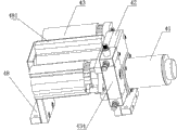
Fig. 1: the structural representation of the utility model embodiment.
Fig. 2: the schematic diagram of blade forming machine structure among the utility model embodiment.
Fig. 3: the schematic diagram of blade shut-off mechanism among the utility model embodiment.
Fig. 4: material casting schematic representation of apparatus in the utility model embodiment blade shut-off mechanism.
Fig. 5: blade is worn the schematic diagram of sheet mechanism among the utility model embodiment.
Fig. 6: blade is worn the side schematic view of sheet mechanism among the utility model embodiment.
Fig. 7: the schematic diagram of impeller plug-in sheet machine structure among the utility model embodiment.
Fig. 8: the utility model embodiment mid-game divides the schematic diagram of disc mechanism.
Fig. 9: the front schematic view that the utility model embodiment mid-game divides disc mechanism.
Figure 10: the schematic diagram of impeller rolling riveter structure among the utility model embodiment.
The specific embodiment
Make a detailed explanation below in conjunction with 1~10 pair of specific embodiment of the present utility model of accompanying drawing.
A kind of metal blast fan automatic moulding machine shown in Fig. 1~10 is worn sheet mechanism 4, impeller inserted sheet mechanism 5, mid-game by frame 1 and blade forming mechanism 2, blade shut-off mechanism 3, blade mounted thereto and is divided disc mechanism 6 and impeller roll riveting mechanism 7 to constitute.
Blade forming mechanism comprises base plate 21, blade forming installing rack 22, stepper motor 23, motor installing rack 24, shaft coupling 25, idle wheel group, organizes roll extrusion wheels 27, left limit post 28a, right limit post 28b more, organizes hold-down devices 29 more, lacks material shutdown inductive switch 211 and adjuster 26.Base plate 21 in the blade forming mechanism 2 is fixedly mounted on the frame 1, and blade forming installing rack 22 is fixed on the base plate 21, and the motor installing rack 24 that stepper motor 23 is installed is on frame 1.Roll extrusion wheels 27 are horizontal from left to right four groups, and hold-down devices 29 is four groups of corresponding also side disposed thereon with roll extrusion wheels 27 quantity.
Moulding on above-mentioned every group of roll extrusion wheels 27 is recessed, and to take turns radius of curvature with shaping cam be that radian is from left to right held gradually and diminished, the radius of curvature that is every group is all inequality, billot is by the roll extrusion wheels of 4 different radians, by repeatedly roll forming, the final blade radian unanimity that forms, whole piece bending blade radius error is minimum.
Hold-down devices 29 is arranged on the blade forming installing rack 22, hold-down devices 29 by pressure adjustment dish 291, compression press spring 292, suppress plate 296, depression bar 293, slide block 294, screw rod 295 and adjust cushion block and connect and compose.Compression press spring 292 is contained in pressure adjustment dish 291 and suppresses between the plate 296, the fixedly connected plate 296 that suppresses in depression bar 293 upper ends, the lower end connects slide block 294, adjust cushion block be arranged on slide block 294 bottoms and position be in moulding recessed take turns and shaping cam between the junction, by adjust cushion block be adjusted to type recessed take turns and shaping cam between the gap, guaranteed the blade of roll extrusion different-thickness.The recessed wheel by slide block 294 of moulding is loaded in the groove of blade forming installing rack 22.Rotation pressure adjustment dish 291 can be adjusted the pretightning force of compression spring 292, thereby adjusts the size of pressure, by moulding recessed take turns with shaping cam with the blade roll forming.
The outside that the position of adjuster 26 is in right limit post 28b promptly links to each other with discharging opening.Adjuster 26 is fixed on the blade forming installing rack 22 by proofreading and correct installing plate 26a.Adjuster 26 is made of adjuster base plate 261, two row's adjuster side plates 262 and correction roller 263, and two row's adjuster side plates 262 are installed in parallel on the adjuster base plate 261, proofread and correct roller 263 and are on the two adjuster base plates of arranging between the adjuster side plates 262 261.Blade after 26 pairs of rolls forming of inspection machine carries out alignment to be handled.
The outside that the position of scarce material shutdown inductive switch 211 is in left limit post 28a is corresponding charging aperture, and scarce material shutdown inductive switch 211 actuator blade shaping mechanisms 2 are closed automatically when lacking material.The discharging opening of blade forming mechanism is corresponding with the charging aperture position of blade shut-off mechanism;
Blade shut-off mechanism 3 mainly comprises two groups of shearing devices 31, two groups of material casting devices 32, guide rail 33, base plate 34 and correcting plates 35.Two groups of shearing devices 31 and two groups of material casting devices 32 all are installed on the frame 1 by base plate 34.
Blade is worn sheet mechanism 4, comprises servomotor 41, gear-box 42, installing rack 48 and two groups of merry-go-round type bunker devices 43.Installing rack 48 is fixed on the frame 1, servomotor 41 links to each other with gear-box 42, two groups of merry-go-round type bunker devices 43 are installed on the installing rack 48, and two groups of merry-go-round type bunker devices 43 link to each other with gear-box 42 respectively, and servomotor 41 is by two groups of merry-go-round type bunker device 43 transpositions of gear-box 42 controls.Two groups of merry-go-round type bunker devices 43 are arranged in parallel, and are symmetrical arranged along the central plate 481 of installing rack, and two groups of merry-go-round type bunker devices 43 are along central plate 481 rotation transformation positions.
Merry-go-round type bunker device 43 comprises feed bin fixed mount 437, bearing material storehouse 435, rotary cylinder 434 and ratchet 436.Bearing material storehouse 435 is installed on the installing rack 48 by feed bin fixed mount 437, ratchet 436 is arranged between bearing material storehouse 435 and the feed bin fixed mount 437, rotary cylinder 434 is installed on the installing rack 48, the output of rotary cylinder 434 links to each other with bearing material storehouse 435, storehouses 435 rotations of rotary cylinder 434 control bearing material, what circular array was set in the bearing material storehouse 435 is used to peg graft the vanes fixed groove of blade.
Blade is worn the benchmark of sheet mechanism 4 when assembling for entire equipment, one of them merry-go-round type bunker device 43 position is corresponding with the material casting outlet of material casting device 32, specifically be the vanes fixed groove position on the bearing material storehouse 435 of one of them merry-go-round type bunker device 43 and the material casting outlet parallel alignment of material casting device 32, and cooperate correspondence, vanes material casting device 32 is thrown in the vanes fixed groove in bearing material storehouse 435.The effect of ratchet 436 is to prevent 435 opposite spins of bearing material storehouse, causes blade can't be thrown into normally in the vanes fixed groove in bearing material storehouse 435.Whenever a slice of dishing out blade, the rotary cylinder 434 of merry-go-round type bunker device 43 rotates once, successively 435 li each the vanes fixed grooves in bearing material storehouse is all filled.The merry-go-round type bunker device 43 of filling blade turns to i.e. two groups of merry-go-round type bunker device 43 transpositions of opposite side under the effect of servomotor 41.
Impeller inserted sheet mechanism 5 is made of inserted sheet cylinder 51, preceding mount pad 52, back mount pad 57, slide plate 53, guide pillar 54, many push rods 55 and edge cover 56.
Preceding mount pad 52 links to each other by 4 guide pillars 54 with back mount pad 57, slide plate 53 is socketed on the guide pillar 54, inserted sheet cylinder 51 outputs link to each other with slide plate 53, inserted sheet cylinder 51 outputs control slide plate 53 moves forward and backward along guide pillar 54, the rear end of push rod 55 is fixed on the slide plate 53, the edge cover 56 before front end passes on the mount pad 52.Many push rods 55 are arranged in annular, and its shape is corresponding with the shape that the vanes fixed groove on the bearing material storehouse 435 is arranged.During action, inserted sheet cylinder 51 outputs push away slide plate 53 forward along guide pillar 54, and the vanes fixed groove on the front end of push rod 55 and the bearing material storehouse 435 aligns, and the front end that pushes up 5 bars 5 promotes blade.Guide pillar 54 is done the guide rail of slide plate 53 simultaneously, and slide plate 53 can be made back and forth movement on guide pillar 54.Push rod 55 is cylindrical, does not adopt with the similar sheet push rod of blade, and cylindricality push rod 55 is easily processed, and can adopt standard component, and push rod length is selected for use on request.
Mid-game divides disc mechanism 6 mainly to comprise branch dish cylinder 61, retainer cylinder 62, material supporting rack 63, material bearing shelf 64, shift fork 67, many mid-game position-limited racks 60, guide rail 66, impeller carriage 65, branch dish machine installing rack 68, pallet installing rack 69, fixed axis 624 and support ears 625.Divide dish machine installing rack 68 and pallet installing rack 69 to be installed on the frame 1.
Impeller roll riveting mechanism 7 comprises that mainly roll riveting base plate 71, roll riveting frame 75, last roll riveting device 74, following roll riveting device 73, bottom roller separate 72 devices, roll riveting motor and hydraulic system.Roll riveting base plate 71 is installed on the frame 1, and the guide pillar 751 on the roll riveting frame 75 is vertically fixed on the roll riveting base plate 71.
Last roll riveting device 74 is installed on the roll riveting frame 75.Last roll riveting device 74 comprises upper mounted plate 741, upper slide 742, goes up rolling wheel 743, upper roller frame 744 and roll riveting oil cylinder 745, upper mounted plate 741 and upper slide 742 are installed on the guide pillar 751 of roll riveting frame 75, last rolling wheel 743 is installed on the upper slide 742 by upper roller frame 744, roll riveting oil cylinder 745 is installed on the upper mounted plate 741, roll riveting oil cylinder 745 outputs connect goes up rolling wheel 743, rolling wheel 743 can move up and down under roll riveting oil cylinder 745 acts on, and impeller is carried out roll riveting.Upper slide 742 the position on the guide pillar 751 adjust up and down rolling wheel 743 and following roll riveting device 73 in the realization between the adjustment of height, impeller that promptly can the roll riveting different-diameter.
Following roll riveting device 73 comprises that side plate 731 is installed in roll riveting down, a plurality of rolling wheel 732, position-limited rack 733 and gear trains 734 down.Following roll riveting is installed side plate 731 and is fixed on the roll riveting base plate 71, a plurality of rolling wheel 732, position-limited rack 733 and gear trains 734 down are installed in roll riveting and install on the side plate 731, following rolling wheel 732 links to each other with gear train 734, and the position of position-limited rack 733 is in the top of rolling wheel 732 down.Roll riveting is installed side plate 731 rear portions and is provided with chute.Each is equipped with the impeller stopper slot 7321 that many groups are parallel to each other on the rolling wheel 732 down, and is respectively equipped with one group of impeller stopper slot 7321 on the two ends, the left and right sides of following rolling wheel 732, and the left side plate of position-limited rack 733 aligns with the left and right end portions of following rolling wheel 732.During roll riveting, the mid-game on the impeller is stuck in the impeller stopper slot 7321, has guaranteed can laterally not moving or beat of impeller, and impeller can be evenly stressed during roll riveting, the impeller quality height that roll riveting forms.
Above-mentioned down rolling wheel 732 is two groups, and one group is installed on roll riveting and installs on the side plate 731 and link to each other with gear train 734, and gear train 734 links to each other with the roll riveting motor, the rotation torque when the impeller roll riveting is provided.Another group and slide block 723 assembling, slide block 723 be along with the output of separation cylinder 721 is made back and forth movement, and after roll riveting was finished, separation cylinder 721 work broke away from rolling wheel 732 down and transmission idle wheel on the gear train 734, and rolling wheel 732 separates under two groups.The direction that material bearing shelf 64 tilts is over against impeller roll riveting mechanism 7, and rolling wheel 732 under the outlet correspondence of material bearing shelf 64, just falls into down on the rolling wheel 732 later in impeller rolls down from material bearing shelf 64.Roll riveting motor and hydraulic system are installed on the frame 1, and the hydraulic oil pipe on the hydraulic system links to each other with roll riveting oil cylinder 745, the roll riveting motor be connected gear train 734 by the rolling riveter belt pulley.
During use, billot blade one end is shut down inductive switch 211 by lacking material, in the roll extrusion wheels 27 of the blade forming mechanism 2 of packing into.Live 27 pairs of billot blades of roll extrusion wheels by four and carry out the roll extrusion processing, the size of pressure is regulated by hold-down devices 29, forms the blade of radian unanimity, and carries out alignment by the blade after 26 pairs of rolls forming of adjuster and handle.To send in the shearing device 31 of blade shut-off mechanism 3, blade is cut off by cutting off die 312 and movable punch 311.Feedstock direction is that the shearing device 31 on the left side does not produce waste material with the cut-out of the blade after the moulding, 31 head waste materials excisions of the shearing device on the right with the moulding rear blade, and waste material is discharged from relief hole.The blade pass of cutting off moulding is crossed material casting device 32 and is thrown into blade and wears in the bearing material storehouse 435 of merry-go-round type bunker device 43 of sheet mechanism 4, whenever a slice of dishing out blade, rotary cylinder 434 control merry-go-round type bunker devices 43 rotate once, successively 435 li each blade grooves in bearing material storehouse are all filled.The merry-go-round type bunker device 43 of filling blade under the effect of servomotor 41 with merry-go-round type bunker device 43 transpositions of an other side, another merry-go-round type bunker device 43 continues to accept the blade that material casting device 32 is dished out.Mid-game is packed in the mid-game draw-in groove of mid-game position-limited rack 60, and the quantity of impeller mid-game can be adjusted according to mid-game position-limited rack 60.Impeller inserted sheet mechanism 5 action, the blades that will fill by push rod 55 in that merry-go-round type bunker device 43 of blade push in the mid-game that is pre-assembled, and this moment, blade was packed in the blade groove of mid-game.Mid-game divides branch dish cylinder 61 actions of disc mechanism 6, and branch dish cylinder 61 moves on guide rail 66 by shift fork 67 control mid-game position-limited racks 60, is about to mid-game distance on request separately.Then retainer cylinder 62 actions, retainer cylinder 62 holds up impeller with impeller carriage 65 jack-up until impeller carriage 65, and height is seasonable with 64 pairs of material bearing shelfs, impeller carriage 65 is towards material bearing shelf 64 deflections, impeller rolls into material bearing shelf 64, rolls into impeller roll riveting mechanism 7 along material bearing shelf 64, just falls into down on the rolling wheel 732 later in impeller rolls down from material bearing shelf 64, following rolling wheel 732 high speed rotating, last rolling wheel 743 is descending to carry out roll riveting to impeller and fixes.Go up rolling wheel 743 after roll riveting is finished and return, the outermost rolling wheel 732 down on the slide block 723 is pulled out in separation cylinder 721 actions, and the impeller after the moulding falls into from gap location and falls, and sends by the deflector chute on the frame.Repeat said process, do roll riveting work next time.
Above-mentioned enforcement only is this patent embodiment preferably, for example to wear the merry-go-round type bunker device 43 in the sheet mechanism 4 also can be 3 groups, 4 groups, 5 groups, 6 groups or more groups to blade, with a certain fulcrum is the center, and servomotor 41 is that center rule rotation gets final product by the many groups of gear-box 42 controls merry-go-round type bunker 43 with this fulcrum; The roll riveting oil cylinder 745 of last roll riveting device 74 also can adopt the structure of cylinder.The protection domain that all belongs to this patent is modified in the structure that all employing the technical program are described, feature and the variation on its spiritual principle.
Claims (10)
1. metal blast fan automatic moulding machine is characterized in that comprising that frame and blade forming mechanism, blade shut-off mechanism, blade mounted thereto wear sheet mechanism, impeller inserted sheet mechanism, mid-game and divide disc mechanism and impeller roll riveting mechanism;
Blade forming mechanism comprises base plate, blade forming installing rack, stepper motor, organizes the roll extrusion wheels more and organizes hold-down devices more; Base plate in the blade forming mechanism is fixedly mounted on the frame, the blade forming installing rack is fixed on the base plate, many group roll extrusion wheels horizontally are installed on the blade forming installing rack, and hold-down devices is continuous with the roll extrusion wheels and quantity is corresponding, and hold-down devices is arranged on the blade forming installing rack;
The blade shut-off mechanism comprises shearing device, material casting device and base plate, and shearing device and material casting device all are installed on the frame by base plate;
Blade is worn sheet mechanism, comprises servomotor, gear-box, installing rack and organizes the merry-go-round type bunker device more; Servomotor links to each other with gear-box, and the merry-go-round type bunker device is installed on the installing rack, and gear-box links to each other with the merry-go-round type bunker device, and installing rack is fixed on the frame;
Impeller inserted sheet mechanism comprises inserted sheet cylinder, preceding mount pad, back mount pad, slide plate, guide pillar, many push rods and inlays cover; Preceding mount pad links to each other by guide pillar with the back mount pad, and slide plate is socketed on the guide pillar, and inserted sheet cylinder output links to each other with slide plate; The rear end of push rod is fixed on the tail skid, the edge cover before front end passes on the mount pad;
Mid-game divides disc mechanism, comprises branch dish cylinder, retainer cylinder, material supporting rack, material bearing shelf, many mid-game position-limited racks, impeller carriage, branch dish machine installing rack and pallet installing racks; Divide dish machine installing rack and pallet installing rack to be installed on the frame, the mid-game position-limited rack is arranged on the branch dish machine installing rack, and branch dish cylinder connects the mid-game position-limited rack; The retainer cylinder links to each other with material supporting rack, and the impeller carriage is installed in the top of material supporting rack, and the position of impeller carriage is corresponding with branch dish machine installing rack, and impeller carriage and material supporting rack are eccentric to be provided with, and material bearing shelf is fixed on the pallet installing rack;
Impeller roll riveting mechanism, comprise roll riveting base plate, roll riveting frame, last roll riveting device, following roll riveting device and bottom roller separator, the roll riveting base plate is fixedly mounted on the frame, the roll riveting frame is fixed on the roll riveting base plate, last roll riveting device is installed on the roll riveting frame, and following roll riveting device is arranged on the roll riveting base plate, and following roll riveting device comprises a plurality of rolling wheels down, last roll riveting device and following rolling wheel cooperate corresponding, and a following rolling wheel of following roll riveting device links to each other with the bottom roller separator.
2. a kind of metal blast fan automatic moulding machine according to claim 1 is characterized in that described blade forming mechanism also comprises motor installing rack, shaft coupling, idle wheel group, left limit post, right limit post, lacks material and shut down inductive switch and adjuster; The motor installing rack that stepper motor is installed is on frame, and stepper motor links to each other with the roll extrusion wheels by shaft coupling; The left limit post is arranged on the outside of the roll extrusion wheels of high order end, the outside of the roll extrusion wheels that are arranged on low order end of right limit post; The position of adjuster is in the outside of right limit post, and adjuster is fixed on the blade forming installing rack by proofreading and correct installing plate; Lack material and shut down the outside that the position of inductive switch is in the left limit post.
3. a kind of metal blast fan automatic moulding machine according to claim 2, it is characterized in that described every group of roll extrusion wheels take turns and constitute with the shaping cam of the band arc plush copper of its coupling by the moulding of band arc groove is recessed, divide two rows to be installed in the blade forming installing rack, to be that moulding is recessed take turns last row, following row is a shaping cam, wherein row's shaping cam directly is connected with blade forming installing rack mount down, and last row's moulding is recessed to be taken turns in the groove that is loaded on the blade forming installing rack; Adjacent roll extrusion wheels all connect by the idle wheel group, and the idle wheel group all is between two shaping cams of adjacent roll extrusion wheels, shaping cam on the roll extrusion wheels of low order end connects stepper motor by shaft coupling, and recessed the wheel with the shaping cam direction of rotation of moulding deviated from mutually; Described hold-down devices by pressure adjustment dish, compression press spring, suppress plate, depression bar, slide block, screw rod and adjustment cushion block and connect and compose; Compression press spring is contained in pressure adjustment dish and suppresses between the plate, the fixedly connected plate that suppresses in depression bar upper end, the lower end connects slide block, adjust cushion block be arranged on slider bottom and position be in moulding recessed take turns and shaping cam between the junction, the recessed wheel by slide block of moulding is loaded in the groove of blade forming installing rack; Adjuster is made of adjuster base plate, two row's adjuster side plates and correction roller, and two row's adjuster side plates are installed in parallel on the adjuster base plate, proofread and correct roller and are on the two adjuster base plates of arranging between the adjuster side plates.
4. a kind of metal blast fan automatic moulding machine according to claim 1 is characterized in that described blade shut-off mechanism also comprises guide rail and correcting plate, and shearing device and material casting device are respectively horizontal two groups; Guide rail is installed on the base plate, and wherein one group of shearing device is movably arranged on the guide rail.
5. a kind of metal blast fan automatic moulding machine according to claim 4, it is characterized in that described shearing device comprises cut-out die, movable punch and cut-out cylinder, movable punch is connected with the output that cuts off cylinder, cuts off on the die the fixedly die edge of a knife is set; Guide rail and base plate are provided for discharging the relief hole of waste material; The material casting device is made of material casting motor, driving gear set, protruding material casting wheel and recessed material casting wheel, the action of material casting driven by motor driving gear set, protruding material casting wheel all links to each other with driving gear set and synchronization action with recessed material casting wheel, and protruding material casting wheel and recessed material casting wheel cooperate corresponding up and down, and protruding material casting wheel deviates from mutually with recessed material casting wheel direction of rotation; The correcting plate is installed in the blade equipped at outlet port of the material casting device in the outside, on the correcting plate guiding groove is set, and the position of guiding groove is corresponding with the blade delivery outlet of material casting device.
6. a kind of metal blast fan automatic moulding machine according to claim 1 is characterized in that described merry-go-round type bunker device is two groups that are arranged in parallel, and is symmetrical arranged along the central plate of installing rack; Described merry-go-round type bunker device comprises feed bin fixed mount, bearing material storehouse, rotary cylinder and ratchet; The bearing material storehouse is installed on the installing rack by the feed bin fixed mount, and ratchet is arranged between bearing material storehouse and the feed bin fixed mount, and rotary cylinder links to each other with the bearing material storehouse, and what circular array was set in the bearing material storehouse is used to peg graft the vanes fixed groove of blade.
7. a kind of metal blast fan automatic moulding machine according to claim 1 is characterized in that many push rods in the described impeller inserted sheet mechanism are arranged in annular, and its shape is corresponding with the shape that the vanes fixed groove on the bearing material storehouse is arranged.
8. a kind of metal blast fan automatic moulding machine according to claim 1 is characterized in that described mid-game divides disc mechanism also to comprise shift fork, guide rail, fixed axis and support ear; Guide rail is fixed on the branch dish machine installing rack, the mid-game position-limited rack is contained on the guide rail and can moves along guide rail, the mid-game draw-in groove of grafting mid-game is set on the mid-game position-limited rack, divide the dish cylinder to link to each other with every mid-game position-limited rack respectively by shift fork, the support ear of impeller carriage bottom it is connected with fixed axis on being assembled in the pallet installing rack; Material bearing shelf tilts to impeller roll riveting mechanism direction; Material bearing shelf is made of material bearing shelf base plate and two blocks of material bearing shelf side plates that are installed on the material bearing shelf base plate.
9. a kind of metal blast fan automatic moulding machine according to claim 1, it is characterized in that the described roll riveting device of going up comprises upper mounted plate, upper slide, goes up rolling wheel, upper roller frame and roll riveting oil cylinder, upper mounted plate and upper slide are installed on the guide pillar of roll riveting frame, last rolling wheel is installed on the upper slide by the upper roller frame, the roll riveting oil cylinder is installed on the upper mounted plate, and roll riveting oil cylinder output connects goes up rolling wheel; Following roll riveting device comprises roll riveting installation side plate and gear train, position-limited rack and a plurality of rolling wheel down mounted thereto down, and following roll riveting is installed side plate and is fixed on the roll riveting base plate, and following rolling wheel links to each other with gear train; Each is equipped with the impeller stopper slot that many groups are parallel to each other on the rolling wheel down, and is respectively equipped with one group of impeller stopper slot on the two ends, the left and right sides of following rolling wheel; The bottom roller separator comprises separation cylinder, limited block, slide block and connecting plate, and outermost rolling wheel down is installed on the slide block, and slide block is fixedlyed connected with connecting plate; The output of separation cylinder links to each other with connecting plate, and limited block is installed in the outer end that side plate is installed in roll riveting under the roll riveting.
10. a kind of metal blast fan automatic moulding machine according to claim 9, it is characterized in that described impeller roll riveting mechanism also comprises roll riveting motor and hydraulic system, guide pillar on the roll riveting frame is vertically fixed on the roll riveting base plate, roll riveting motor and hydraulic system are installed on the frame, hydraulic oil pipe on the hydraulic system links to each other with the roll riveting oil cylinder, the roll riveting motor be connected gear train by the rolling riveter belt pulley.
Priority Applications (1)
| Application Number | Priority Date | Filing Date | Title |
|---|---|---|---|
| CN2010206063247U CN201950461U (en) | 2010-11-12 | 2010-11-12 | Automatic forming machine for metal fan impeller |
Applications Claiming Priority (1)
| Application Number | Priority Date | Filing Date | Title |
|---|---|---|---|
| CN2010206063247U CN201950461U (en) | 2010-11-12 | 2010-11-12 | Automatic forming machine for metal fan impeller |
Publications (1)
| Publication Number | Publication Date |
|---|---|
| CN201950461U true CN201950461U (en) | 2011-08-31 |
Family
ID=44494588
Family Applications (1)
| Application Number | Title | Priority Date | Filing Date |
|---|---|---|---|
| CN2010206063247U Expired - Lifetime CN201950461U (en) | 2010-11-12 | 2010-11-12 | Automatic forming machine for metal fan impeller |
Country Status (1)
| Country | Link |
|---|---|
| CN (1) | CN201950461U (en) |
Cited By (2)
| Publication number | Priority date | Publication date | Assignee | Title |
|---|---|---|---|---|
| CN102126135A (en) * | 2010-11-12 | 2011-07-20 | 四川朗迪塑胶电器有限公司 | Automatic forming machine for metal fan impeller |
| CN110181120A (en) * | 2019-06-28 | 2019-08-30 | 杭州老板电器股份有限公司 | Impeller manufacturing equipment |
-
2010
- 2010-11-12 CN CN2010206063247U patent/CN201950461U/en not_active Expired - Lifetime
Cited By (3)
| Publication number | Priority date | Publication date | Assignee | Title |
|---|---|---|---|---|
| CN102126135A (en) * | 2010-11-12 | 2011-07-20 | 四川朗迪塑胶电器有限公司 | Automatic forming machine for metal fan impeller |
| CN102126135B (en) * | 2010-11-12 | 2012-11-21 | 四川朗迪塑胶电器有限公司 | Automatic forming machine for metal fan impeller |
| CN110181120A (en) * | 2019-06-28 | 2019-08-30 | 杭州老板电器股份有限公司 | Impeller manufacturing equipment |
Similar Documents
| Publication | Publication Date | Title |
|---|---|---|
| CN102126135B (en) | Automatic forming machine for metal fan impeller | |
| CN102120297B (en) | Automatic assembly machine for metal fan impeller | |
| EP2145552B1 (en) | Manufacturing machine for producing combination cigarette filters | |
| CN101444813B (en) | Metal blade forming machine | |
| CN107599034B (en) | A kind of space cam formula broccoli automatic dicer and its block cutting method | |
| CN109494950A (en) | A kind of embedding paper equipment of stator | |
| CN201960214U (en) | Gear milling production line for bimetallic band saw blade | |
| CN105598532B (en) | Veneer color-coating line removes aluminium sheet burring machine | |
| CN103441618A (en) | Motor rotor automatic snap spring and bearing pressing machine | |
| CN201330094Y (en) | Blanking and delivery mechanism of PP plate cutting machine and PP plate cutting device | |
| CN201950461U (en) | Automatic forming machine for metal fan impeller | |
| CN209709905U (en) | A kind of embedding paper equipment of stator | |
| CN201881139U (en) | Automatic assembling machine for metal fan impeller | |
| CN109551816A (en) | A kind of crimping grooving systems of corrugated paper plate printing machines | |
| CN201333479Y (en) | Metal leaf forming machine | |
| CN205464607U (en) | Various coating line of veneer removes aluminum plate burr machine | |
| CN103085101A (en) | Fully automatic cuber | |
| CN110238331A (en) | A kind of bending machine of sleeper production | |
| CN205128811U (en) | Automatic line of little flat nail | |
| CN108996210B (en) | Cylindrical part feeding equipment and using method thereof | |
| CN203330310U (en) | Electronic component pin cutting device | |
| CN207712806U (en) | A kind of automatic positioning row disk device | |
| CN114148010B (en) | Belted layer feeding frame | |
| CN203857878U (en) | Production line of firework and firecracker fuse inserting machine | |
| CN103976599B (en) | Drawstring preform machine |
Legal Events
| Date | Code | Title | Description |
|---|---|---|---|
| C14 | Grant of patent or utility model | ||
| GR01 | Patent grant | ||
| CX01 | Expiry of patent term |
Granted publication date: 20110831 |
|
| CX01 | Expiry of patent term |