CN201933604U - Rainwater drainage multi-passage inspection well - Google Patents
Rainwater drainage multi-passage inspection well Download PDFInfo
- Publication number
- CN201933604U CN201933604U CN2010206056493U CN201020605649U CN201933604U CN 201933604 U CN201933604 U CN 201933604U CN 2010206056493 U CN2010206056493 U CN 2010206056493U CN 201020605649 U CN201020605649 U CN 201020605649U CN 201933604 U CN201933604 U CN 201933604U
- Authority
- CN
- China
- Prior art keywords
- rainwater
- manhole
- multichannel
- discharged
- discharge line
- Prior art date
- Legal status (The legal status is an assumption and is not a legal conclusion. Google has not performed a legal analysis and makes no representation as to the accuracy of the status listed.)
- Expired - Lifetime
Links
Images


Landscapes
- Sewage (AREA)
Abstract
The utility model discloses a rainwater drainage multi-passage inspection well, comprising a well body (2), wherein the well body (2) is internally provided with at least two rainwater outlets (6a, 6b, 6d) that are used for draining rainwater; and each rainwater outlet (6a, 6b, 6d) is connected with different rainwater drainage pipelines (7a, 7b, 7d) respectively. The additional rainwater drainage pipelines are used for being communicated with other rainwater branch pipelines of the system or rainwater line pipelines of adjacent systems, thus changing the condition that the original inspection well has one drainage outlet only. During the raining in the city, when a certain section of rainwater pipeline of the system is difficult to drain water, the rainwater flow that is accumulated in the rainwater pipeline and can not be drained in time can flow to other rainwater pipelines through the additional rainwater drainage pipelines in the inspection well; by adopting the method of additionally arranging the drainage outlets, the difficulty of water drainage can be relieved, and the phenomenon of accumulating water can be reduced.
Description
Technical field
The utility model relates to a kind of manhole, relates in particular to a kind of rainwater removal system self and manhole that is connected each other of being used for.
Background technology
The storm sewer system in urban construction district props up spool, storm sewer, manhole and river course outlet opening by inlet for stom water, inlet for stom water and forms, each bar storm sewer (comprising that inlet for stom water props up spool and river course outlet opening) is connected by manhole, a plurality of storm sewers that enter can be arranged in manhole, but discharge downstream have only a storm sewer.During rainfall, accept in the manhole through one and prop up the rainwater that spool enters to a plurality of inlets for stom water and inlet for stom water, the rainwater that enters to a plurality of upstreams storm sewer through can also be arranged, rainwater more on inspection in the well unique discharge storm sewer discharge rainwater downstream.When certain section storm sewer generation draining at need, the rainwater that can not in time drain can upstream manhole and storm sewer (comprising that inlet for stom water props up spool) savings, forms the pressure current draining, when serious, the rainwater of savings can rise to ground, forms excess surface water.
Summary of the invention
The purpose of this utility model is exactly only to have a rainwater discharge line for the manhole that overcomes above-mentioned prior art, when running into rainwater discharge difficult problem, provide a kind of rainwater to discharge the multichannel manhole, it is on the basis that existing manhole constitutes that this rainwater is discharged the multichannel manhole, increases the manhole of effective connection of rainwater discharge line.
The rainwater discharge line that increases is used to be communicated with the rainwater cable tubing of other rainwater branched line pipeline of native system or adjacent system, has changed the situation that former manhole has only a discharge outlet.In the rainfall of city, when certain section storm sewer draining of certain system at need, can allow the amount of rainfall that in time to get rid of in this storm sewer flow to other storm sewer by the rainwater discharge line that increases in the utility model manhole, utilize the way that increases discharge outlet, alleviate the draining difficulty, reduce the phenomenon that ponding takes place.
For realizing the purpose of this utility model, provide following technical scheme:
A kind of rainwater is discharged the multichannel manhole, has the well body, and well body inside has at least two rainwater outlets that are used to discharge rainwater, and each rainwater outlet connects different rainwater discharge lines respectively.
Wherein, well body inside has with inlet for stom water and props up the rainwater inlet that spool links to each other.
Wherein, well body inside has with rainwater and enters the rainwater inlet that pipeline links to each other.
Wherein, well body inside has with inlet for stom water and props up the rainwater inlet that spool links to each other, and enters the rainwater inlet that pipeline links to each other with rainwater.
Particularly, downward aspect in exit in each described rainwater discharge line self-check well or horizontal aspect are arranged.
Particularly, each described rainwater discharge line can be a different tube diameters; Its elevation of interior end of each described rainwater discharge line can be different.
Particularly, the manhole that is adjacent respectively of each described rainwater discharge line or river course outlet opening link to each other.
Perhaps, the manhole that the part in the described rainwater discharge line is adjacent respectively links to each other, and another part links to each other with the river course outlet opening respectively.
Particularly, described rainwater outlet opening and coupled rainwater discharge line can be the circle that can effectively discharge rainwater, square or polymorphic structure.
The beneficial effects of the utility model embody in the following areas:
1, rainwater discharge multichannel manhole of the present utility model is provided with the rainwater discharge line more than two, the storm sewer that increases is used to be communicated with the rainwater cable tubing of other rainwater branched line pipeline of native system and adjacent system, has changed the situation that former manhole has only a discharge outlet.In the rainfall of city, when certain section storm sewer draining of certain system at need, can allow the amount of rainfall that in time to get rid of in this storm sewer flow to other storm sewer by the rainwater discharge line that increases in the utility model manhole, utilize the way that increases discharge outlet, alleviate the draining difficulty, reduce the phenomenon that ponding takes place.
2, for the not enough present situation storm sewer of rain-water drainage standard, as rebuild existing storm sewer comparatively at need, can on existing storm sewer, rainwater be set and discharge the multichannel manhole,, improve the drainability of existing storm sewer by increasing the rainwater discharge line.
Description of drawings
Fig. 1 is the main pseudosection that rainwater of the present utility model is discharged the multichannel manhole;
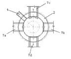
Fig. 2 is the top cross-sectional view that rainwater of the present utility model is discharged the multichannel manhole;
Fig. 3 adopts rainwater of the present utility model to discharge the rainwater removal system floor map that the multichannel manhole forms.
Description of reference numerals: the 1-rainwater is discharged the multichannel manhole; 2-well body; The 2a-pit shaft; The 3-well lid; The 4-inlet for stom water props up spool; 4a-rainwater inlet; The 5-shaft bottom; 6c-rainwater inlet; The 7c-rainwater enters pipeline; 6a, 6b, the outlet of 6d-rainwater; 7a, 7b, 7d-rainwater discharge line; 8-storm sewer manhole; Boundary line, 9-rainwater basin; The 10-river course.
The specific embodiment
Discharge the main pseudosection of multichannel manhole as Fig. 1 rainwater of the present utility model, and shown in the top cross-sectional view of Fig. 2 rainwater discharge of the present utility model multichannel manhole, rainwater of the present utility model is discharged multichannel manhole 1 and is had the well body 2 that is built into by concrete, masonry, the upper end of well body 2 forms pit shaft 2a, well lid 3 is stamped on the top of pit shaft 2a, and wherein the intracavity diameter of pit shaft 2a is little than the intracavity diameter of well body 2.The top of well body 2 has with inlet for stom water and props up the rainwater inlet 4a that spool 4 communicates, so that rainwater props up spool 4 by inlet for stom water and flows in the well body 2, well body 2 bottoms have with rainwater and enter the rainwater inlet 6c that pipeline 7c communicates, so that rainwater enters pipeline 7c by rainwater and flows in the well body 2, well body 2 bottoms have at least two and are used for rainwater outlet 6a, 6b, the 6d that rainwater is discharged, each rainwater outlet 6a, 6b, 6d connect different rainwater discharge line 7a, 7b, 7d respectively, as shown in Figure 1, 2, so that the rainwater that flows in the well body 2 is flowed out by this rainwater discharge line 7a, 7b, 7d.Rainwater discharge line shown in Fig. 1,2 is three, is respectively 7a, 7b, 7d.
Wherein, inlet for stom water prop up spool 4 and rainwater enter pipeline 7c can be for a plurality of, a plurality of inlets for stom water prop up that spool 4 and rainwater enter pipeline 7c and rainwater discharge line 7a, 7b, 7d can be the parts that rainwater of the present utility model is discharged the multichannel manhole.
Again as shown in Figure 1, 2, article three, rainwater discharge line 7a, 7b, 7d are along the downward aspect of water (flow) direction, also can be flat slope, but can not be aspect upwards, and the caliber of three rainwater discharge line 7a, 7b, 7d and elevation of the interior end can be the same also can be different.Like this, make the rainwater that accumulates in the well body 2 to flow out from three rainwater discharge line 7a, 7b, 7d, even a rainwater discharge line wherein takes place to stop up or the draining difficulty, rainwater still can flow away from other rainwater discharge line, thereby alleviates high water level pressure and reduce the phenomenon that ponding takes place.
Rainwater outlet opening 6a, 6b, 6d and coupled rainwater discharge line 7a, 7b, 7d can be the circle that can effectively discharge rainwater, square or polymorphic structure.
Be illustrated in figure 3 as and adopt rainwater of the present utility model to discharge the floor map of the storm sewer system of multichannel manhole formation, the rainwater among the figure is discharged multichannel manhole 1 and is had two rainwater discharge line 7a, 7b.As shown in Figure 3, because discharging multichannel manhole 1, rainwater has two rainwater discharge line 7a, 7b, article two, rainwater discharge line 7a, 7b links to each other with a manhole of adjacency respectively, perhaps directly link to each other with the rainwater outlet of leading to river course 10, the rainwater of make assembling is flowed through rainwater can be along two rainwater discharge line 7a after discharging multichannel manhole 1,7b flows to two different directions, like this, even a rainwater discharge line wherein takes place to stop up or the draining difficulty, rainwater still can flow away from other rainwater discharge line, more help the rapid discharge of rainwater, reduce the incidence of ponding, improve the unobstructed property of safety of draining.
Although above the utility model has been done detailed description; but the utility model is not limited thereto; those skilled in the art can make amendment according to principle of the present utility model; therefore, all various modifications of carrying out according to principle of the present utility model all should be understood to fall into protection domain of the present utility model.
Claims (10)
1. a rainwater is discharged the multichannel manhole, has well body (2), it is characterized in that, well body (2) inside has at least two rainwater outlets that are used to discharge rainwater, and each rainwater outlet connects different rainwater discharge lines respectively.
2. rainwater as claimed in claim 1 is discharged the multichannel manhole, it is characterized in that, described well body (2) inside has with inlet for stom water and props up the rainwater inlet that spool (4) links to each other.
3. rainwater as claimed in claim 1 is discharged the multichannel manhole, it is characterized in that, described well body (2) inside has with rainwater and enters the rainwater inlet that pipeline (7c) links to each other.
4. rainwater as claimed in claim 1 is discharged the multichannel manhole, it is characterized in that, described well body (2) inside has with inlet for stom water and props up the rainwater inlet that spool (4) links to each other, and enters the rainwater inlet that pipeline (7c) links to each other with rainwater.
5. discharge the multichannel manhole as the arbitrary described rainwater of claim 1-4, it is characterized in that downward aspect in exit in each described rainwater discharge line self-check well or horizontal aspect are arranged.
6. rainwater as claimed in claim 5 is discharged the multichannel manhole, it is characterized in that the caliber difference of each described rainwater discharge line.
7. rainwater as claimed in claim 6 is discharged the multichannel manhole, it is characterized in that its elevation difference of interior end of each described rainwater discharge line.
8. rainwater as claimed in claim 7 is discharged the multichannel manhole, it is characterized in that, manhole that each described rainwater discharge line is adjacent respectively or river course outlet opening link to each other.
9. rainwater as claimed in claim 7 is discharged the multichannel manhole, it is characterized in that, the manhole that the part in the described rainwater discharge line is adjacent respectively links to each other, and another part links to each other with the river course outlet opening respectively.
10. rainwater as claimed in claim 1 is discharged the multichannel manhole, it is characterized in that described rainwater outlet opening and coupled rainwater discharge line are circle, the square structures that can effectively discharge rainwater.
Priority Applications (1)
| Application Number | Priority Date | Filing Date | Title |
|---|---|---|---|
| CN2010206056493U CN201933604U (en) | 2010-06-01 | 2010-11-12 | Rainwater drainage multi-passage inspection well |
Applications Claiming Priority (3)
| Application Number | Priority Date | Filing Date | Title |
|---|---|---|---|
| CN201020219958.7 | 2010-06-01 | ||
| CN201020219958 | 2010-06-01 | ||
| CN2010206056493U CN201933604U (en) | 2010-06-01 | 2010-11-12 | Rainwater drainage multi-passage inspection well |
Publications (1)
| Publication Number | Publication Date |
|---|---|
| CN201933604U true CN201933604U (en) | 2011-08-17 |
Family
ID=44445129
Family Applications (1)
| Application Number | Title | Priority Date | Filing Date |
|---|---|---|---|
| CN2010206056493U Expired - Lifetime CN201933604U (en) | 2010-06-01 | 2010-11-12 | Rainwater drainage multi-passage inspection well |
Country Status (1)
| Country | Link |
|---|---|
| CN (1) | CN201933604U (en) |
Cited By (2)
| Publication number | Priority date | Publication date | Assignee | Title |
|---|---|---|---|---|
| CN104563159A (en) * | 2014-12-25 | 2015-04-29 | 永亨控股集团有限公司 | Anti-overflow inspection well |
| CN110700375A (en) * | 2019-10-12 | 2020-01-17 | 闫志伟 | Waterlogging prevention flood diversion equipment for urban heavy rain |
-
2010
- 2010-11-12 CN CN2010206056493U patent/CN201933604U/en not_active Expired - Lifetime
Cited By (3)
| Publication number | Priority date | Publication date | Assignee | Title |
|---|---|---|---|---|
| CN104563159A (en) * | 2014-12-25 | 2015-04-29 | 永亨控股集团有限公司 | Anti-overflow inspection well |
| CN104563159B (en) * | 2014-12-25 | 2015-11-25 | 永亨控股集团有限公司 | A kind of manhole of anti-spill-out |
| CN110700375A (en) * | 2019-10-12 | 2020-01-17 | 闫志伟 | Waterlogging prevention flood diversion equipment for urban heavy rain |
Similar Documents
| Publication | Publication Date | Title |
|---|---|---|
| CN204023750U (en) | Municipal drainage system | |
| CN105544698A (en) | Separate system pipe network based area fragmented rainwater abandoned flow treatment system | |
| CN206530363U (en) | One kind can the outer drainage system of maintenance type railway tunnel bottom structure | |
| CN205153099U (en) | Rainwater flow discarding device | |
| CN203383854U (en) | Buffering system for solving problem of tunnel local sudden water burst | |
| CN206844095U (en) | Grid type rain-water drainage and collection system | |
| CN201933604U (en) | Rainwater drainage multi-passage inspection well | |
| CN202273312U (en) | Vacuum drainage system for draining rainwater of urban underpass road | |
| CN206418520U (en) | A kind of comprehensive pipe gallery structure for accessing storm sewer | |
| CN203383853U (en) | Buffering system for solving problem of insufficient drainage ability of tunnel central ditch | |
| CN206385741U (en) | A kind of siphon drainge system for building | |
| CN102268896B (en) | Meshed rainwater pipeline drainage system | |
| CN201794149U (en) | Siphoning device for discharging clarified water of tailing reservoir | |
| CN103422566B (en) | Multifunctional flow-dividing well | |
| CN215630124U (en) | Urban rainwater pipe gallery | |
| CN104563200A (en) | Tunnel fire-fighting system taking road surface water and tunnel surge water as water sources | |
| CN201933503U (en) | Groundwater guiding and discharging system below anti-seepage membrane of storage yard of industrial waste residue | |
| CN204370519U (en) | A kind of domatic flowing water and road surface water of utilizing is as the tunnel fire protection system at water source | |
| CN214006283U (en) | Drainage structure for rainwater gravity flow crossing roof deformation joint | |
| CN104878822A (en) | Excess rainwater storage and drainage system and method | |
| CN107366294A (en) | A kind of combined drainage system of basement | |
| CN205935150U (en) | Rain water pipe assembly | |
| CN106193262A (en) | A kind of rain dirt mixed flow pipeline Vatch basin | |
| CN104652525A (en) | Tunnel fire-fighting system using slope surface flowing water and pavement water as water sources | |
| CN204370510U (en) | A kind of road surface water and Tunnel Gushing of utilizing is as the tunnel fire protection system at water source |
Legal Events
| Date | Code | Title | Description |
|---|---|---|---|
| C14 | Grant of patent or utility model | ||
| GR01 | Patent grant | ||
| CX01 | Expiry of patent term |
Granted publication date: 20110817 |
|
| CX01 | Expiry of patent term |