CN201916649U - Riffling buffer conveying pipe - Google Patents
Riffling buffer conveying pipe Download PDFInfo
- Publication number
- CN201916649U CN201916649U CN2010206572054U CN201020657205U CN201916649U CN 201916649 U CN201916649 U CN 201916649U CN 2010206572054 U CN2010206572054 U CN 2010206572054U CN 201020657205 U CN201020657205 U CN 201020657205U CN 201916649 U CN201916649 U CN 201916649U
- Authority
- CN
- China
- Prior art keywords
- pipeline
- steel ball
- delivery pipe
- sand setting
- riffling
- Prior art date
- Legal status (The legal status is an assumption and is not a legal conclusion. Google has not performed a legal analysis and makes no representation as to the accuracy of the status listed.)
- Expired - Fee Related
Links
Images

Abstract
The utility model relates to a riffling buffer conveying pipe in pipeline field, which comprises a pipeline A, a pipeline B and a steel ball, wherein a mouth at the lower end of the pipeline A is sealed, and the steel ball is placed in a sealed end; and one side of the pipeline wall of the pipeline A corresponding to the upper part of the steel ball is provided with an open mouth and is connected with one end of the pipeline B, and the other side of the pipeline wall of the pipeline A is provided with an observation hole with a hole cover. The buffer conveying pipe not only can efficiently solve the abrasion caused by impact of riffling on an elbow part of the conveying pipe, but also can efficiently ensure the normal operation of riffling conveying process.
Description
[technical field]
The utility model relates to the pipeline field, especially relates to the sand setting buffering delivery pipe that is used to carry sand setting.
[background technique]
At present, be used to carry the pipeline of sand setting to be the steel warp architecture in ore-dressing practice, its elbow portion will bear the sand setting impact that pressure is 0.6-0.7Mpa at work, with reference to accompanying drawing 1, so the easy utmost point wearing and tearing of the bend part of sand sediment pipe; In order to guarantee the normal operation of course of conveying, must regularly change the abrading section of sand sediment pipe, and long owing to changing the required time, labor intensity is big, not only increase user's cost of production, also influenced the normal operation of sand setting course of conveying greatly.
[summary of the invention]
In order to overcome the deficiency in the background technique, the utility model provides a kind of sand setting buffering delivery pipe, described buffering delivery pipe not only can effectively solve the wearing and tearing that the impact of sand setting causes the delivery pipe bend part, and can effectively guarantee the normal operation of sand setting course of conveying.
For achieving the above object, the utility model adopts following technological scheme:
A kind of sand setting buffering delivery pipe, described delivery pipe comprises pipeline A, pipeline B and steel ball; Described pipeline A lower end ferrule, and in sealed end, be placed with steel ball; Tube wall one side of the corresponding steel ball upper side of pipeline A position is provided with the end of opening and connecting tube B, and the tube wall opposite side setting of pipeline A simultaneously has the peep hole of port lid.
Described sand setting buffering delivery pipe, the steel ball in the described pipeline A sealed end is provided with three layers.
Described sand setting buffering delivery pipe, described pipeline A is clockwise horizontal angle with pipeline B and is connected for 20~30 °.
Owing to adopt aforesaid technological scheme, the utlity model has following beneficial effect:
The wearing and tearing that the impact that sand setting buffering delivery pipe described in the utility model can effectively solve sand setting causes the delivery pipe bend part, not only prolonged the working life of pipeline, reduced labor intensity of operating personnel, also effectively guaranteed the normal operation of sand setting course of conveying simultaneously, for the user has saved cost of production.
[description of drawings]
Fig. 1 is the schematic representation of existing sand sediment pipe;
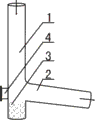
Fig. 2 is the schematic representation of buffering delivery pipe described in the utility model.
Among the figure: 1, pipeline A; 2, pipeline B; 3, steel ball; 4, peep hole; 5, sand sediment pipe.
[embodiment]
Can explain the utility model in more detail by the following examples, open the purpose of this utility model is intended to protect all changes and improvements in the utility model scope, and the utility model is not limited to the following examples;
2 described a kind of sand settings cushion delivery pipes in conjunction with the accompanying drawings, and described delivery pipe comprises pipeline A 1, pipeline B 2 and steel ball 3; Described pipeline A 1 lower end ferrule, and in sealed end, be placed with steel ball 3, promptly utilize steel ball 3 to cushion of the impact of the sand setting of whereabouts to bend part; For reaching better cushioning effect, the steel ball 3 in pipeline A 1 sealed end can be set to three layers, impact that not only can the efficient buffer sand setting, and the flow velocity of sand setting also influenced not quite; Higher slightly tube wall one side in pipeline A 1 corresponding steel ball, 3 upper side positions is provided with opening, and the corresponding end with pipeline B 2 of opening is tightly connected, and promptly the sand setting in the pipeline A 1 just flows to into pipeline B 2 after by steel ball 3 bufferings; For better making in the sand setting flow ipe B 2, pipeline A 1 can be connected for 20~30 ° with clockwise horizontal angle with pipeline B 2; The tube wall opposite side setting of pipeline A 1 has the peep hole 4 of port lid, promptly can utilize peep hole 4 to observe the abrasion condition of steel ball 3, so that in time add steel ball 3.
Implement sand setting buffering delivery pipe described in the utility model, when pressure is that the sand setting of 0.6-0.7MPa is when vertically falling, behind the steel ball 3 of sand setting among impulse piping A 1 that falls among the ability flow ipe B 2, so, the impact that sand setting produces in course of conveying will be born by steel ball 3, and direct shock delivery pipe, thereby formed protection to the delivery pipe bend part; In addition, observe the degree that steel ball 3 is worn, and in time add new steel ball 3 and just can effectively guarantee managing the buffering of interior sand setting by the port lid of opening peep hole 4.
Carefully not stating in the above content is prior art partly, does not state so run business into particular one.
Claims (3)
1. sand setting buffering delivery pipe, it is characterized in that: described delivery pipe comprises pipeline A(1), pipeline B(2) and steel ball (3); Described pipeline A(1) lower end ferrule, and in sealed end, be placed with steel ball (3); Pipeline A(1) tube wall one side of corresponding steel ball (3) upper side position is provided with opening and connecting tube B(2) an end, pipeline A(1 simultaneously) the setting of tube wall opposite side have the peep hole (4) of port lid.
2. sand setting buffering delivery pipe according to claim 1, it is characterized in that: described pipeline A(1) steel ball (3) in the sealed end is provided with three layers.
3. sand setting according to claim 1 buffering delivery pipe is characterized in that: described pipeline A(1) with pipeline B(2) be clockwise horizontal angle and be connected for 20~30 °.
Priority Applications (1)
| Application Number | Priority Date | Filing Date | Title |
|---|---|---|---|
| CN2010206572054U CN201916649U (en) | 2010-12-14 | 2010-12-14 | Riffling buffer conveying pipe |
Applications Claiming Priority (1)
| Application Number | Priority Date | Filing Date | Title |
|---|---|---|---|
| CN2010206572054U CN201916649U (en) | 2010-12-14 | 2010-12-14 | Riffling buffer conveying pipe |
Publications (1)
| Publication Number | Publication Date |
|---|---|
| CN201916649U true CN201916649U (en) | 2011-08-03 |
Family
ID=44416445
Family Applications (1)
| Application Number | Title | Priority Date | Filing Date |
|---|---|---|---|
| CN2010206572054U Expired - Fee Related CN201916649U (en) | 2010-12-14 | 2010-12-14 | Riffling buffer conveying pipe |
Country Status (1)
| Country | Link |
|---|---|
| CN (1) | CN201916649U (en) |
Cited By (2)
| Publication number | Priority date | Publication date | Assignee | Title |
|---|---|---|---|---|
| CN103851291A (en) * | 2014-01-13 | 2014-06-11 | 洛阳智邦石化设备有限公司 | Novel flushing-resistant air cushion elbow |
| CN104045039A (en) * | 2014-06-11 | 2014-09-17 | 苏州柏德纳科技有限公司 | Guide rod |
-
2010
- 2010-12-14 CN CN2010206572054U patent/CN201916649U/en not_active Expired - Fee Related
Cited By (2)
| Publication number | Priority date | Publication date | Assignee | Title |
|---|---|---|---|---|
| CN103851291A (en) * | 2014-01-13 | 2014-06-11 | 洛阳智邦石化设备有限公司 | Novel flushing-resistant air cushion elbow |
| CN104045039A (en) * | 2014-06-11 | 2014-09-17 | 苏州柏德纳科技有限公司 | Guide rod |
Similar Documents
| Publication | Publication Date | Title |
|---|---|---|
| CN201916649U (en) | Riffling buffer conveying pipe | |
| CN201827598U (en) | Buffer pipeline | |
| CN204051798U (en) | The online ball adding device of a kind of coal pulverizer | |
| CN205347468U (en) | Blast furnace stave prosthetic devices | |
| CN203173185U (en) | Down-stream type bin pump | |
| CN203927198U (en) | A kind of wear-resisting airduct elbow | |
| CN202228839U (en) | Washing-preventing pipeline elbow | |
| CN202927343U (en) | Novel wear-resistant elbow | |
| CN201066013Y (en) | Buffer elbow | |
| CN202195215U (en) | Wearable three-way pipeline | |
| CN204005254U (en) | A kind of novel lime slurry pipe controller | |
| CN203663802U (en) | Vacuum feeding and discharging device of reaction kettle | |
| CN202901662U (en) | Wear-resisting bend | |
| CN202203554U (en) | Negative pressure sealing flange connection device | |
| CN202402923U (en) | Device for recovering leaked oil of hammer lever | |
| CN203273158U (en) | Bend connection pipe | |
| CN202021082U (en) | Dredging funnel water gun | |
| CN204693021U (en) | A kind of LNG liquid addition machine safety protection device | |
| CN204784670U (en) | Take buffer's pressure vessel | |
| CN202056450U (en) | Pulp transmission pipeline elbow | |
| CN201154267Y (en) | By-path device of compressed air pipeline of pulsed bag-type collector | |
| CN203030251U (en) | Discharge pipe of reaction kettle | |
| CN201103762Y (en) | Buffering T-junction | |
| CN201949929U (en) | Wear-resisting sand sediment pipe | |
| CN202510986U (en) | Automatic pulp discharge device of low-fall pipeline |
Legal Events
| Date | Code | Title | Description |
|---|---|---|---|
| C14 | Grant of patent or utility model | ||
| GR01 | Patent grant | ||
| C17 | Cessation of patent right | ||
| CF01 | Termination of patent right due to non-payment of annual fee |
Granted publication date: 20110803 Termination date: 20121214 |