CN201896011U - Rope head device for tension automatic balancing of elevator traction steel rope - Google Patents
Rope head device for tension automatic balancing of elevator traction steel rope Download PDFInfo
- Publication number
- CN201896011U CN201896011U CN2010206379786U CN201020637978U CN201896011U CN 201896011 U CN201896011 U CN 201896011U CN 2010206379786 U CN2010206379786 U CN 2010206379786U CN 201020637978 U CN201020637978 U CN 201020637978U CN 201896011 U CN201896011 U CN 201896011U
- Authority
- CN
- China
- Prior art keywords
- pulley
- steel rope
- traction sheave
- counterweight
- walk around
- Prior art date
- Legal status (The legal status is an assumption and is not a legal conclusion. Google has not performed a legal analysis and makes no representation as to the accuracy of the status listed.)
- Expired - Fee Related
Links
Images


Abstract
The utility model provides a rope head device for tension automatic balancing of an elevator traction steel rope, which can realize automatic balancing of the tension of the elevator traction steel rope, improve the comfortableness of operation of an elevator, prolong the service life of the steel rope, and reduce the amount of onsite maintenance. The starting end and the termination end of the steel rope are respectively fixed on a car side pulley block and/or on a counterweight side pulley block, and the middle section of the steel rope repeatedly bypasses traction wheels, pulleys and traction wheels on the car side pulley block and pulleys on the counterweight side pulley block.
Description
Technical field
The utility model is a kind of steel wire rope tension self-equalizing fag end device.
Technical background
At present, the traction elevator of the various uses that in building, is provided with, according to its load carrying ability, speed, principal parameters such as hoisting depth, by the calculating of safety coefficient, general traction elevator will dispose several steel ropes.Like this, in elevator installation and debug process,, need the commissioning staff to adjust the elasticity of steel rope, thereby make several steel wire rope tension equilibriums in order to make the elevator operation more comfortable.But in actual Engineering Projects, the tension force complete equilibrium of several steel ropes often can not 100% realizes that it is stressed bigger to cause adjusting tighter steel rope, and the steel rope of adjusting pine is stressed less.When steel rope and rope sheave engagement, the vibration of generation interferes with each other, and influences the comfort level of elevator operation, and the service life of having reduced steel rope, and on-the-spot adjustment maintenance workload is also bigger.And the command speed of elevator is high more, and such phenomenon is obvious more.
The utility model content
The purpose of this utility model provides a kind of tension force automatic equalization that makes the elevator traction steel rope, thereby improves the comfort level of elevator operation, prolongs the service life of steel rope, reduces the on-the-spot steel wire rope tension self-equalizing fag end device of adjusting maintenance workload.
This towed elevator steel wire rope tension self-equalizing fag end device, the initiating terminal and the clearing end that are steel cable are separately fixed on cage side pulley base and/or the counterweight sideslip wheel seat, and the interlude of steel rope is walked around the pulley on pulley on traction sheave, the cage side pulley base, traction sheave, the counterweight sideslip wheel seat repeatedly.
Described fag end device can be that the initiating terminal of steel cable is fixed on the cage side pulley base, and this steel rope is walked around traction sheave then, walk around the pulley of counterweight sideslip wheel seat, walk around traction sheave, walk around the pulley on the cage side pulley base after, walk around traction sheave again, walk around again on the pulley of counterweight sideslip wheel seat, walk around traction sheave again, walk around the pulley on the cage side pulley base again, walk around traction sheave again, the rest may be inferred, and the clearing end of steel rope is fixed on cage side pulley base or the counterweight sideslip wheel seat.
Described fag end device can also be that the initiating terminal of steel cable is fixed on the counterweight sideslip wheel seat, and this steel rope is walked around traction sheave then, walk around the pulley of cage side pulley base, walk around traction sheave, walk around the pulley on the counterweight sideslip wheel seat after, walk around traction sheave again, walk around again on the pulley of cage side pulley base, walk around traction sheave again, walk around the pulley of counterweight sideslip wheel seat again, walk around traction sheave again, the rest may be inferred, and the clearing end of steel rope is fixed on cage side pulley base or the counterweight sideslip wheel seat.
Above-mentioned fag end device, the interlude of steel rope are walked around the pulley on pulley on traction sheave, track adjusting wheel, the cage side pulley base, track adjusting wheel, traction sheave, the counterweight sideslip wheel seat repeatedly.
Because the utility model steel rope is actual is that steel cable is by the fixing middle mode of walking around pulley in two ends, whenever walk around a pulley and be equivalent to one of traditional steel rope radical increase, but in fact with independently mode is different separately between traditional steel rope root and the root, therefore, when the steel rope bearing load, tension force on every steel rope is balanced, i.e. tension force=total weight on every steel rope/walk around number of share of stock of pulley.That is to say that the number of times of walking around pulley by steel cable forms number of share of stock, thereby replace in original traditional mode independently steel rope radical, reach the purpose of automatic equalization.Therefore no matter the traction steel-cable number of share of stock what, can be by this fag end device with the balancing tension of each strand steel wire rope.It is applicable to various traction elevators, such as passenger elevator, and sightseeing elevator, Medical Service Elevator, cargo lift etc.
Description of drawings
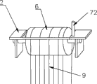
Fig. 1 is the scheme drawing of embodiment 1.
Fig. 2 is the partial enlarged drawing of cage side pulley base among Fig. 1 etc.
Fig. 3 is the scheme drawing of embodiment 2.
Fig. 4 is the partial enlarged drawing of cage side pulley base among Fig. 3 etc.
Fig. 5 is the partial enlarged drawing of counterweight sideslip wheel seat among Fig. 3 etc.
The specific embodiment
Referring to Fig. 1,3, steel wire rope tension self-equalizing fag end device comprises, cable wire end 7 (comprising steel rope initiating terminal 71, steel rope clearing end 72), steel rope 9 and be used for self-balanced pulley 6 and pulley base (comprising cage side pulley base 1 and counterweight sideslip wheel seat 2) of pulley 6 etc. is set.
Cage side pulley base 1 is fixed on car 3 one sides.Counterweight sideslip wheel seat 2 is fixed on counterweight 4 one sides.Steel rope initiating terminal 71 (causing with conventional cord is first) is fixed on an end of cage side pulley base 1.Steel rope is walked around traction sheave 5, return on the pulley of the counterweight sideslip wheel seat 2 of the track adjusting wheel grooving arrival other end, walk around traction sheave, the track adjusting wheel grooving arrives at the pulley on the cage side pulley base 1, after walking around the pulley on the cage side pulley base 1, turn back to the pulley on the counterweight sideslip wheel seat 2 again, walk around the pulley on the counterweight sideslip wheel seat 2 after, return again, the rest may be inferred, until satisfying steel rope 9 radicals (number of share of stock) that are fit to.When steel rope radical (number of share of stock) was even number, steel rope clearing end 72 was fixed on cage side pulley base 1, sees Fig. 2.When steel rope radical (number of share of stock) was odd number, steel rope clearing end 72 was fixed on the counterweight sideslip wheel seat 2, sees Fig. 5.
Technical characterstic of the present utility model is that pulley base is fixed on car and counterweight one side.Described cable wire end (causing with conventional cord is first) is fixed on an end of a pulley base (can be referred to as the initiating terminal pulley base, can be cage side pulley base 1, also counterweight sideslip wheel seat 2).Steel rope is walked around traction sheave, the track adjusting wheel grooving arrives on the pulley of another pulley base (can be referred to as the clearing end pulley base) and returns, and walks around traction sheave, the track adjusting wheel grooving, arrive at initiating terminal pulley base top sheave, after walking around the initiating terminal pulley, turn back to clearing end pulley base top sheave again, walk around clearing end pulley base pulley after, return again, the rest may be inferred, and after satisfying the steel rope radical that is fit to, cable wire end is fixed on the pulley base.When steel rope radical (number of share of stock) is even number, steel rope initiating terminal and steel rope clearing end all are fixed on the initiating terminal pulley base, when steel rope radical (number of share of stock) was odd number, the steel rope initiating terminal was fixed on the initiating terminal pulley base, and the steel rope clearing end is fixed on the clearing end pulley base.
The utility model is applicable to that lanyard is than n: 1 (n is a natural number).This fag end device is applicable to the elevator suspension system, both has been applicable to the traction elevator of direct drive, also is applicable to the traction elevator of indirect driving.
Claims (4)
1. towed elevator steel wire rope tension self-equalizing fag end device, it is characterized in that: the initiating terminal of steel cable and clearing end are separately fixed on cage side pulley base and/or the counterweight sideslip wheel seat, and the interlude of steel rope is walked around the pulley on pulley on traction sheave, the cage side pulley base, traction sheave, the counterweight sideslip wheel seat repeatedly.
2. fag end device as claimed in claim 1, it is characterized in that: the initiating terminal of steel cable is fixed on the cage side pulley base, this steel rope is walked around traction sheave then, walk around the pulley of counterweight sideslip wheel seat, walk around traction sheave, after walking around the pulley on the cage side pulley base, walk around traction sheave again, walk around again on the pulley of counterweight sideslip wheel seat, walk around traction sheave again, walk around the pulley on the cage side pulley base again, walk around traction sheave again, the rest may be inferred, and the clearing end of steel rope is fixed on cage side pulley base or the counterweight sideslip wheel seat.
3. fag end device as claimed in claim 1, it is characterized in that: the initiating terminal of steel cable is fixed on the counterweight sideslip wheel seat, this steel rope is walked around traction sheave then, walk around the pulley of cage side pulley base, walk around traction sheave, after walking around the pulley on the counterweight sideslip wheel seat, walk around traction sheave again, walk around again on the pulley of cage side pulley base, walk around traction sheave again, walk around the pulley of counterweight sideslip wheel seat again, walk around traction sheave again, the rest may be inferred, and the clearing end of steel rope is fixed on cage side pulley base or the counterweight sideslip wheel seat.
4. fag end device as claimed in claim 1 is characterized in that: the interlude of steel rope is walked around the pulley on pulley on traction sheave, track adjusting wheel, the cage side pulley base, track adjusting wheel, traction sheave, the counterweight sideslip wheel seat repeatedly.
Priority Applications (1)
| Application Number | Priority Date | Filing Date | Title |
|---|---|---|---|
| CN2010206379786U CN201896011U (en) | 2010-11-30 | 2010-11-30 | Rope head device for tension automatic balancing of elevator traction steel rope |
Applications Claiming Priority (1)
| Application Number | Priority Date | Filing Date | Title |
|---|---|---|---|
| CN2010206379786U CN201896011U (en) | 2010-11-30 | 2010-11-30 | Rope head device for tension automatic balancing of elevator traction steel rope |
Publications (1)
| Publication Number | Publication Date |
|---|---|
| CN201896011U true CN201896011U (en) | 2011-07-13 |
Family
ID=44253925
Family Applications (1)
| Application Number | Title | Priority Date | Filing Date |
|---|---|---|---|
| CN2010206379786U Expired - Fee Related CN201896011U (en) | 2010-11-30 | 2010-11-30 | Rope head device for tension automatic balancing of elevator traction steel rope |
Country Status (1)
| Country | Link |
|---|---|
| CN (1) | CN201896011U (en) |
Cited By (2)
| Publication number | Priority date | Publication date | Assignee | Title |
|---|---|---|---|---|
| CN102009897A (en) * | 2010-11-30 | 2011-04-13 | 江苏佛斯特电梯有限公司 | Elevator wire rope tension automatic balancing rope end device |
| CN104973490A (en) * | 2015-05-25 | 2015-10-14 | 上海浦东开灵电梯厂有限公司 | Novel floating type counterweight device capable of precisely adjusting balance |
-
2010
- 2010-11-30 CN CN2010206379786U patent/CN201896011U/en not_active Expired - Fee Related
Cited By (2)
| Publication number | Priority date | Publication date | Assignee | Title |
|---|---|---|---|---|
| CN102009897A (en) * | 2010-11-30 | 2011-04-13 | 江苏佛斯特电梯有限公司 | Elevator wire rope tension automatic balancing rope end device |
| CN104973490A (en) * | 2015-05-25 | 2015-10-14 | 上海浦东开灵电梯厂有限公司 | Novel floating type counterweight device capable of precisely adjusting balance |
Similar Documents
| Publication | Publication Date | Title |
|---|---|---|
| CN106315349A (en) | Automatic tension balancing device and method of multi-rope winding hoisting steel wire ropes for deep vertical shaft | |
| TW200702276A (en) | Elevator installation | |
| CN205419426U (en) | Tow wire rope tension balancing unit | |
| CN201896011U (en) | Rope head device for tension automatic balancing of elevator traction steel rope | |
| CN103803383B (en) | A kind of elevator traction system | |
| CN209383241U (en) | The heavy-load type elevator structure of traction ratio 6:1 | |
| CN105110140A (en) | Load change adaptive steel wire rope traction lifting system | |
| CN202124389U (en) | Fag end device capable of automatically balancing tensile force of steel wire rope | |
| CN102476772A (en) | Rope head device for automatically balancing tensile force of wire rope | |
| CN102491153B (en) | Design of traction system of 6:1 motor-room-free cargo elevator | |
| CN202148122U (en) | Traction device used for elevator traction and transmission | |
| CN202124390U (en) | Tensile force automatic-balance rope end device of steel wire rope | |
| CN102009897A (en) | Elevator wire rope tension automatic balancing rope end device | |
| CN207903714U (en) | Driven elevators are set in one kind | |
| CN203333119U (en) | Pulling rope elevator | |
| CN102476773A (en) | Automatic tension balancing rope head device for steel wire rope | |
| CN205442328U (en) | Two car elevators | |
| CN201217594Y (en) | Draw transmission mechanism with primary and secondary counterweight | |
| CN107673163A (en) | A kind of stable lift car guide wheel device | |
| CN202729537U (en) | Underlying indirect-drive elevator | |
| CN201686368U (en) | Right angle door opening knapsack frame elevator | |
| CN102515003A (en) | Traction elevator without counterpoise operation | |
| CN103303767A (en) | Stress balancing safety mechanism for elevator traction steel wire rope group | |
| CN201713185U (en) | Backpack-type car frame system for elevator | |
| CN202717479U (en) | Ultra high-speed elevator weight compensation device |
Legal Events
| Date | Code | Title | Description |
|---|---|---|---|
| C14 | Grant of patent or utility model | ||
| GR01 | Patent grant | ||
| C17 | Cessation of patent right | ||
| CF01 | Termination of patent right due to non-payment of annual fee |
Granted publication date: 20110713 Termination date: 20121130 |