CN201876148U - Heat energy recycling device for magnetic core material sintering furnace - Google Patents
Heat energy recycling device for magnetic core material sintering furnace Download PDFInfo
- Publication number
- CN201876148U CN201876148U CN2010206457709U CN201020645770U CN201876148U CN 201876148 U CN201876148 U CN 201876148U CN 2010206457709 U CN2010206457709 U CN 2010206457709U CN 201020645770 U CN201020645770 U CN 201020645770U CN 201876148 U CN201876148 U CN 201876148U
- Authority
- CN
- China
- Prior art keywords
- section
- energy recovery
- heat energy
- core material
- recovery pipe
- Prior art date
- Legal status (The legal status is an assumption and is not a legal conclusion. Google has not performed a legal analysis and makes no representation as to the accuracy of the status listed.)
- Expired - Fee Related
Links
Images


Classifications
-
- Y—GENERAL TAGGING OF NEW TECHNOLOGICAL DEVELOPMENTS; GENERAL TAGGING OF CROSS-SECTIONAL TECHNOLOGIES SPANNING OVER SEVERAL SECTIONS OF THE IPC; TECHNICAL SUBJECTS COVERED BY FORMER USPC CROSS-REFERENCE ART COLLECTIONS [XRACs] AND DIGESTS
- Y02—TECHNOLOGIES OR APPLICATIONS FOR MITIGATION OR ADAPTATION AGAINST CLIMATE CHANGE
- Y02P—CLIMATE CHANGE MITIGATION TECHNOLOGIES IN THE PRODUCTION OR PROCESSING OF GOODS
- Y02P10/00—Technologies related to metal processing
- Y02P10/25—Process efficiency
Landscapes
- Furnace Details (AREA)
Abstract
The utility model relates to a heat energy recycling device for a magnetic core material sintering furnace, which is mainly used for drying magnetic core materials. The magnetic core material sintering device which is commonly used at present has low utilization rate of energy sources, and is difficult to achieve purposes of energy saving and emission reduction. The heat energy recycling device comprises a heating pipe, a heating drainage section, a binder removal section, a fast temperature rise section, a holding section and an air-cooled cooling section, wherein the heating drainage section, the binder removal section, the fast temperature rise section, the holding section and the air-cooled cooling section are sequentially connected, and the heating pipe is connected onto the heating drainage section. The heat energy recycling device is characterized by also comprising a fan and a heat energy recovery pipe, and a hot air outlet is arranged in the air-cooled cooling section; one end of the heat energy recovery pipe is connected with the hot air outlet of the air-cooled cooling section, and the other end of the heat energy recovery pipe is connected with the heating drainage section; and the fan is arranged in the hot air outlet of the air-cooled cooling section and is matched with the heat energy recovery pipe. The heat energy recycling device has a reasonable structural design, low production cost, high work efficiency and high utilization rate of energy sources, and is easy to manufacture.
Description
Technical field
The utility model relates to a kind of core material drying unit, especially relates to a kind of core material sintering kiln energy recovery re-use device, is mainly used in the oven dry core material.
Background technology
The core material drying unit that is used to dry core material at present commonly used comprises heating tube, adds the warm water discharge section, binder removal section, the section of being rapidly heated, soaking zone and wind cooling temperature lowering section, wherein add warm water discharge section, binder removal section, the section of being rapidly heated, soaking zone and wind cooling temperature lowering section and be connected successively, heating tube with add the warm water discharge section and be connected.Core material to be dried enters from the import that adds the warm water discharge section and adds the warm water discharge section, then successively through binder removal section, the section of being rapidly heated, soaking zone and wind cooling temperature lowering section, exports from the outlet of wind cooling temperature lowering section at last.Outside heat energy is by in the heating tube input core material drying unit, dries, binder removal, intensification, insulation and temperature-fall period.Waste heat after the cooling is discharged from the wind cooling temperature lowering section.The heat of discharging has more than 100 ℃.
Because the core material sintering equipment generally all is installed in the workshop, and core material drying unit temperature inside is very high, can reach more than 1300 ℃ as the temperature in the soaking zone, make that a large amount of heat energy is discharged to the workshop from the wind cooling temperature lowering section in the core material drying unit, cause the room temperature in the workshop very high, the feasible non-constant of working environment that is positioned at the workman in workshop, serious threat is healthy to the workman's, simultaneously also natural environment has been caused thermal pollution, wasted the energy, improve production cost, made the energy be difficult to obtain reasonable use.
Summary of the invention
The purpose of this utility model is to overcome above shortcomings in the prior art, and a kind of reasonable in design is provided, and easy to manufacture, production cost is low, high efficiency, the core material sintering kiln energy recovery re-use device that energy utilization rate is high.
The technical scheme in the invention for solving the above technical problem is: this core material sintering kiln energy recovery re-use device comprises heating tube, add the warm water discharge section, the binder removal section, the section of being rapidly heated, soaking zone and wind cooling temperature lowering section, the described warm water discharge section that adds, the binder removal section, the section of being rapidly heated, soaking zone is connected successively with the wind cooling temperature lowering section, described heating tube is connected and adds on the warm water discharge section, its characteristics are: also comprise blower fan and energy recovery pipe, be provided with hot-blast outlet in the described wind cooling temperature lowering section, one end of described energy recovery pipe is connected with hot-blast outlet in the wind cooling temperature lowering section, the other end of this energy recovery pipe with add the warm water discharge section and be connected, described blower fan is installed in the hot-blast outlet of wind cooling temperature lowering section, and this blower fan matches with the energy recovery pipe.
Energy recovery pipe described in the utility model is provided with heat-insulation layer.
The section of being rapidly heated described in the utility model is provided with several exhaust outlets.
The utility model compared with prior art, have the following advantages and effect: inner waste heat enters in the energy recovery pipe by the hot-blast outlet of blower fan from the wind cooling temperature lowering section, enter once more by the energy recovery pipe then and add in the warm water discharge section, it is recycling to make heat energy obtain, improved rate of energy, reduce production cost, improved operating efficiency; Because inner waste heat is not discharged in the workshop by the wind cooling temperature lowering section, can effectively reduce the room temperature in the workshop, has reduced thermal pollution, helps improving workman's working environment.
Of the present utility model simple in structure, reasonable in design, scientific arrangement, energy-conserving and environment-protective, market prospects are wide.
Description of drawings
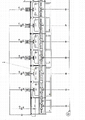
Fig. 1 is the structural representation of core material sintering kiln energy recovery re-use device among the utility model embodiment.
Fig. 2 is the structural representation that adds the warm water discharge section among the utility model embodiment.
Fig. 3 is the structural representation of binder removal section among the utility model embodiment.
Fig. 4 is the structural representation of the section of being rapidly heated among the utility model embodiment.
Fig. 5 is the structural representation of soaking zone among the utility model embodiment.
Fig. 6 is the structural representation of air-cooled temperature descending section among the utility model embodiment.
The specific embodiment
The utility model is described in further detail below in conjunction with accompanying drawing and by embodiment, and following examples are to explanation of the present utility model and the utility model is not limited to following examples.
Embodiment:
Referring to Fig. 1 to Fig. 6, core material sintering kiln energy recovery re-use device in the present embodiment comprises and adds warm water discharge section 1, binder removal section 2, the section of being rapidly heated 3, soaking zone 4, wind cooling temperature lowering section 5, heating tube 6, blower fan and energy recovery pipe 7, wherein the section of being rapidly heated 3 is provided with three exhaust outlets 31, and energy recovery pipe 7 is provided with heat-insulation layer.
Add warm water discharge section 1, binder removal section 2, the section of being rapidly heated 3, soaking zone 4 and wind cooling temperature lowering section 5 in the present embodiment are connected successively, core material to be dried enters from adding warm water discharge section 1, then successively through binder removal section 2, the section of being rapidly heated 3 and soaking zone 4, at last from 5 outputs of wind cooling temperature lowering section.
Heating tube 6 in the present embodiment is connected and adds on the warm water discharge section 1, extraneous heat energy can be by heating tube 6 supply in core material sintering kiln energy recovery re-use device.
Present embodiment is provided with hot-blast outlet in wind cooling temperature lowering section 5, an end of energy recovery pipe 7 is connected with hot-blast outlet in the wind cooling temperature lowering section 5, the other end of this energy recovery pipe 7 with add warm water discharge section 1 and be connected.Blower fan in the present embodiment is installed in the hot-blast outlet of wind cooling temperature lowering section 5, this blower fan matches with energy recovery pipe 7, waste heat in the wind cooling temperature lowering section 5 can be guided in the energy recovery pipe 7 by blower fan, be back to through energy recovery pipe 7 then add carry out in the warm water discharge section 1 recycling.
Core material sintering kiln energy recovery re-use device in the present embodiment is used to dry core material, core material to be dried is from add warm water discharge section 1, then successively through binder removal section 2, the section of being rapidly heated 3 and soaking zone 4, at last from 5 outputs of wind cooling temperature lowering section, core material promptly to be dried process is successively heated drainage period, binder removal phase, the phase of being rapidly heated, soak and wind cooling temperature lowering phase, thereby reaches the purpose of oven dry.The heat energy that is used for core material sintering kiln energy recovery re-use device is made up of two parts, a part is come in from extraneous supply by heating tube 6, another part is the heat energy by energy recovery pipe 7 recycling inside, this part heat energy is successively through adding warm water discharge section 1, binder removal section 2, the section of being rapidly heated 3, soaking zone 4 and wind cooling temperature lowering section 5, be back to by energy recovery pipe 7 at last and add in the warm water discharge section 1, reach the purpose of heat energy recycling thus, realized energy-saving and emission-reduction.
Certainly, in wind cooling temperature lowering section 5 of the present utility model, also can be provided with several hot-blast outlets, a blower fan all is installed in each hot-blast outlet, from energy recovery pipe 7, extend several arms and be connected with a hot-blast outlet respectively; In energy recovery pipe 7 of the present utility model, can also be provided with several air-introduced machines.Need to prove, in the utility model to add warm water discharge section 1, binder removal section 2, the section of being rapidly heated 3, soaking zone 4 and wind cooling temperature lowering section 5 same as the prior art or close, so locate no longer to describe in detail.
Above content described in this specification only is to the explanation of the utility model structure example.The utility model person of ordinary skill in the field can make various modifications or replenishes or adopt similar mode to substitute described specific embodiment; only otherwise depart from structure of the present utility model or surmount the defined scope of these claims, all should belong to protection domain of the present utility model.
Claims (3)
1. core material sintering kiln energy recovery re-use device, comprise heating tube, add the warm water discharge section, the binder removal section, the section of being rapidly heated, soaking zone and wind cooling temperature lowering section, the described warm water discharge section that adds, the binder removal section, the section of being rapidly heated, soaking zone is connected successively with the wind cooling temperature lowering section, described heating tube is connected and adds on the warm water discharge section, it is characterized in that: also comprise blower fan and energy recovery pipe, be provided with hot-blast outlet in the described wind cooling temperature lowering section, one end of described energy recovery pipe is connected with hot-blast outlet in the wind cooling temperature lowering section, the other end of this energy recovery pipe with add the warm water discharge section and be connected, described blower fan is installed in the hot-blast outlet of wind cooling temperature lowering section, and this blower fan matches with the energy recovery pipe.
2. core material sintering kiln energy recovery re-use device according to claim 1, it is characterized in that: described energy recovery pipe is provided with heat-insulation layer.
3. core material sintering kiln energy recovery re-use device according to claim 1, it is characterized in that: the described section of being rapidly heated is provided with several exhaust outlets.
Priority Applications (1)
| Application Number | Priority Date | Filing Date | Title |
|---|---|---|---|
| CN2010206457709U CN201876148U (en) | 2010-12-07 | 2010-12-07 | Heat energy recycling device for magnetic core material sintering furnace |
Applications Claiming Priority (1)
| Application Number | Priority Date | Filing Date | Title |
|---|---|---|---|
| CN2010206457709U CN201876148U (en) | 2010-12-07 | 2010-12-07 | Heat energy recycling device for magnetic core material sintering furnace |
Publications (1)
| Publication Number | Publication Date |
|---|---|
| CN201876148U true CN201876148U (en) | 2011-06-22 |
Family
ID=44164065
Family Applications (1)
| Application Number | Title | Priority Date | Filing Date |
|---|---|---|---|
| CN2010206457709U Expired - Fee Related CN201876148U (en) | 2010-12-07 | 2010-12-07 | Heat energy recycling device for magnetic core material sintering furnace |
Country Status (1)
| Country | Link |
|---|---|
| CN (1) | CN201876148U (en) |
Cited By (3)
| Publication number | Priority date | Publication date | Assignee | Title |
|---|---|---|---|---|
| CN111649581A (en) * | 2020-06-24 | 2020-09-11 | 河南科技大学 | Calcination binder removal system that alloy powder extruded part used |
| CN112944902A (en) * | 2021-02-01 | 2021-06-11 | 高帅 | Sintering furnace convenient for recycling residual heat and utilization method thereof |
| CN113470956A (en) * | 2021-06-04 | 2021-10-01 | 罗延平 | Device for processing binder removal before sintering of soft magnetic ferrite by positive and negative bevel method |
-
2010
- 2010-12-07 CN CN2010206457709U patent/CN201876148U/en not_active Expired - Fee Related
Cited By (5)
| Publication number | Priority date | Publication date | Assignee | Title |
|---|---|---|---|---|
| CN111649581A (en) * | 2020-06-24 | 2020-09-11 | 河南科技大学 | Calcination binder removal system that alloy powder extruded part used |
| CN111649581B (en) * | 2020-06-24 | 2021-12-03 | 河南科技大学 | Calcination binder removal system that alloy powder extruded part used |
| CN112944902A (en) * | 2021-02-01 | 2021-06-11 | 高帅 | Sintering furnace convenient for recycling residual heat and utilization method thereof |
| CN113470956A (en) * | 2021-06-04 | 2021-10-01 | 罗延平 | Device for processing binder removal before sintering of soft magnetic ferrite by positive and negative bevel method |
| CN113470956B (en) * | 2021-06-04 | 2023-06-30 | 海宁凌通磁业科技有限公司 | Device for processing glue discharged before sintering soft magnetic ferrite by positive and negative oblique angles |
Similar Documents
| Publication | Publication Date | Title |
|---|---|---|
| CN201876148U (en) | Heat energy recycling device for magnetic core material sintering furnace | |
| CN103820963B (en) | Setting machine with drying oven | |
| CN103017501A (en) | Wet object drying method and wet object drying device | |
| CN209459461U (en) | Coating machine oven waste-heat recovery device | |
| CN202209852U (en) | Hot air drying device | |
| CN102853538A (en) | Novel hot-blast stove | |
| CN202973806U (en) | Energy-saving type drying device | |
| CN104567334A (en) | Energy-saving type heat recovery air source high-temperature drying machine | |
| CN205747699U (en) | A kind of baking room of band dehumidification function | |
| CN108344260A (en) | Wood industry plank drying unit | |
| CN201868156U (en) | Energy-saving hot-air circulatory heating furnace for drying enamelled wire | |
| CN204115496U (en) | A kind of residual heat of tunnel kiln utilize device | |
| CN202254730U (en) | Energy-saving drying device | |
| CN206540399U (en) | A kind of device of multistage continuous drying material | |
| CN203116487U (en) | Waste-heat utilization drying kiln | |
| CN202630102U (en) | Intercooling tower hot-air recycling system in thermal power plant | |
| CN202599067U (en) | Drying tower waste heat recycling device | |
| CN204373367U (en) | A kind of energy-saving recuperation of heat air source high temperature drying machine | |
| CN203157350U (en) | Drying box thermal circulation system for printer | |
| CN205939363U (en) | Utilize thermal system of keeping warm in winter of enamelling machine baker | |
| CN204678679U (en) | A kind of used heat reuse hot-cast socket type air-heater | |
| CN203795176U (en) | Setting machine with drying oven | |
| CN202178113U (en) | Apparatus enabling waste heat of enamelling machine to be used for continuous annealing of drawing machine | |
| CN204421503U (en) | A kind of energy-conservation building machine of all things drying machine | |
| CN204227739U (en) | A kind of novel warm-air machine |
Legal Events
| Date | Code | Title | Description |
|---|---|---|---|
| C14 | Grant of patent or utility model | ||
| GR01 | Patent grant | ||
| CF01 | Termination of patent right due to non-payment of annual fee |
Granted publication date: 20110622 Termination date: 20141207 |
|
| EXPY | Termination of patent right or utility model |