CN201868579U - Grounding wire clip used for testing - Google Patents
Grounding wire clip used for testing Download PDFInfo
- Publication number
- CN201868579U CN201868579U CN201020571419XU CN201020571419U CN201868579U CN 201868579 U CN201868579 U CN 201868579U CN 201020571419X U CN201020571419X U CN 201020571419XU CN 201020571419 U CN201020571419 U CN 201020571419U CN 201868579 U CN201868579 U CN 201868579U
- Authority
- CN
- China
- Prior art keywords
- wire clip
- sawtooth
- clip body
- saw teeth
- wire
- Prior art date
- Legal status (The legal status is an assumption and is not a legal conclusion. Google has not performed a legal analysis and makes no representation as to the accuracy of the status listed.)
- Expired - Fee Related
Links
Images

Landscapes
- Installation Of Indoor Wiring (AREA)
Abstract
The utility model discloses a grounding wire clip used for testing which belongs to the field of power transmission, and comprises a wire clip body, wherein a bolt is fixed on the wire clip on body, a lower side plate of the wire clip body is provided with a threaded hole, a rotating part is arranged in the threaded hole, the top end of the rotating part is provided with a fastener, and the inner side of an upper side plate of the wire clip body is provided with saw teeth which comprise triangular saw teeth and rectangular saw teeth. In the utility model, the saw teeth arranged at the inner side of the upper side plate of the wire clip body are the triangular saw teeth and the rectangular saw teeth which are arranged at intervals, the bottoms of the triangular saw teeth are relatively sharp so as to wear off an insulating layer on a grounding down wire, while the rectangular saw teeth can ensure better contact between the wire clip and the grounding down wire.
Description
Technical field
The utility model belongs to field of power transmission, is specifically related to a kind of earthing clamp of testing usefulness.
Background technology
In electric power apparatus examination and maintenance process, need be fixed on the down conductor with earthing clamp, existing earthing clamp as shown in Figure 1, comprise wire clip body 2, be fixed with bolt 6 on the wire clip body 2, wire clip body 2 lower side panels are provided with screwed hole, be provided with revolving part 7 in the screwed hole, revolving part 7 tops are provided with securing member 3, wire clip body 2 epipleural inboards are provided with sawtooth, sawtooth on this device all is triangular in shape, when the surface oxidation of down conductor or surface have when insulating barrier such as spraying paint, by moving of earthing clamp, utilize leg-of-mutton sharp sawtooth to grind off the insulating barrier on down conductor 1 surface, can realize being communicated with between wire clamp and the down conductor 1, but owing to be a contact or line contact between triangle sawtooth bottom and the down conductor, the contact between wire clamp and the down conductor 1 is still undesirable.
The utility model content
The technical problems to be solved in the utility model be earthing clamp with down conductor between contact badly, a kind of test earthing clamp that can well contact with down conductor is provided.
The technical solution of the utility model realizes in the following manner:
A kind of test earthing clamp, comprise wire clip body, be fixed with bolt on the wire clip body, the wire clip body lower side panel is provided with screwed hole, be provided with revolving part in the screwed hole, the revolving part top is provided with securing member, and wire clip body epipleural inboard is provided with sawtooth, and described sawtooth comprises triangle sawtooth and rectangle sawtooth.
Described triangle sawtooth and rectangle zigzag intervals distribute.
Described securing member end face is provided with triangle sawtooth spaced apart and rectangle sawtooth.
In the utility model, the sawtooth of wire clip body epipleural inboard is that triangle and rectangle are spaced, the bottom of triangle sawtooth is more sharp-pointed, can grind off the insulating barrier on the down conductor, and the rectangle sawtooth then can be so that the contact gear ratio between wire clamp and the down conductor be better.
Description of drawings
Fig. 1 is the user mode figure of prior art.
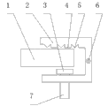
Fig. 2 is the user mode schematic diagram of the utility model embodiment 1.
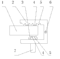
Fig. 3 is the user mode schematic diagram of the utility model embodiment 2.
Embodiment
As shown in Figure 2, present embodiment comprises wire clip body 2, be fixed with bolt 6 on the wire clip body 2, wire clip body 2 lower side panels are provided with screwed hole, be provided with revolving part 7 in the screwed hole, revolving part 7 tops are provided with securing member 3, and wire clip body 2 epipleural inboards are provided with sawtooth, and described sawtooth comprises triangle sawtooth 5 and rectangle sawtooth 4.Described triangle sawtooth 5 and rectangle sawtooth 4 are spaced apart.
The utility model use is as follows: the top that down conductor 1 is placed on securing member 3, turning revolving part 7 moves up securing member 3, clamp down conductor, if there is insulating barrier on down conductor 1 top layer, move left and right wire clip body then, utilize triangle sawtooth 5 to grind off insulating barrier, making has excellent contact between wire clamp and the down conductor.
As shown in Figure 3, securing member 3 end faces are provided with triangle sawtooth 5 spaced apart and rectangle sawtooth 4.Other structures and execution mode are with embodiment 1.
Claims (3)
1. test earthing clamp, comprise wire clip body (2), be fixed with bolt (6) on the wire clip body (2), wire clip body (2) lower side panel is provided with screwed hole, be provided with revolving part (7) in the screwed hole, revolving part (7) top is provided with securing member (3), and wire clip body (2) epipleural inboard is provided with sawtooth, it is characterized in that: described sawtooth comprises triangle sawtooth (5) and rectangle sawtooth (4).
2. test earthing clamp according to claim 1 is characterized in that: described triangle sawtooth (5) and rectangle sawtooth (4) are spaced apart.
3. test earthing clamp according to claim 1 is characterized in that: described securing member (3) end face is provided with triangle sawtooth (5) spaced apart and rectangle sawtooth (4).
Priority Applications (1)
| Application Number | Priority Date | Filing Date | Title |
|---|---|---|---|
| CN201020571419XU CN201868579U (en) | 2010-10-22 | 2010-10-22 | Grounding wire clip used for testing |
Applications Claiming Priority (1)
| Application Number | Priority Date | Filing Date | Title |
|---|---|---|---|
| CN201020571419XU CN201868579U (en) | 2010-10-22 | 2010-10-22 | Grounding wire clip used for testing |
Publications (1)
| Publication Number | Publication Date |
|---|---|
| CN201868579U true CN201868579U (en) | 2011-06-15 |
Family
ID=44139724
Family Applications (1)
| Application Number | Title | Priority Date | Filing Date |
|---|---|---|---|
| CN201020571419XU Expired - Fee Related CN201868579U (en) | 2010-10-22 | 2010-10-22 | Grounding wire clip used for testing |
Country Status (1)
| Country | Link |
|---|---|
| CN (1) | CN201868579U (en) |
Cited By (2)
| Publication number | Priority date | Publication date | Assignee | Title |
|---|---|---|---|---|
| CN103311689A (en) * | 2013-05-18 | 2013-09-18 | 马栋梁 | Wire clamp system for power equipment |
| CN103378424A (en) * | 2012-04-16 | 2013-10-30 | 国家电网公司 | Emergency live-line processing device for high voltage joint heating |
-
2010
- 2010-10-22 CN CN201020571419XU patent/CN201868579U/en not_active Expired - Fee Related
Cited By (3)
| Publication number | Priority date | Publication date | Assignee | Title |
|---|---|---|---|---|
| CN103378424A (en) * | 2012-04-16 | 2013-10-30 | 国家电网公司 | Emergency live-line processing device for high voltage joint heating |
| CN103378424B (en) * | 2012-04-16 | 2016-10-05 | 国家电网公司 | The emergent electrical treatment device of high pressure connection heating |
| CN103311689A (en) * | 2013-05-18 | 2013-09-18 | 马栋梁 | Wire clamp system for power equipment |
Similar Documents
| Publication | Publication Date | Title |
|---|---|---|
| CN201868579U (en) | Grounding wire clip used for testing | |
| CN204558687U (en) | A kind of earth potential live operation penetrating cable clamp for insulated conductor connection | |
| CN202225160U (en) | Assembly and disassembly device for porcelain insulator base screw | |
| CN201853584U (en) | Automatic junction device for furnace bottom of bogie-hearth resistance furnace | |
| CN202690601U (en) | Base connection part | |
| CN204927774U (en) | Manual terminal press -connection machine | |
| CN203673902U (en) | Resistor element for brake resistor device | |
| CN203895646U (en) | Novel crimping-type quick binding post and LED linear lamp | |
| CN202564578U (en) | Cable line connector | |
| CN202949062U (en) | Large current joint device | |
| CN202768588U (en) | Bolt for putting up iron of automobile | |
| CN106990377B (en) | 10kV switch cabinet current transformer test fixture | |
| CN202280715U (en) | Conducting bolt | |
| CN203013971U (en) | A grounding wire clamp in a power transmission line | |
| CN203056263U (en) | Anti-loosening power strip with elastic metal clamping pieces | |
| CN203386588U (en) | Sleeve pipe with high insulating performance | |
| CN204216831U (en) | Photovoltaic module support and photovoltaic component system | |
| CN203567335U (en) | Scraping strip device for polycrystalline silicon solar positive electrode printing oblique angles | |
| CN203150451U (en) | Illuminated toggle switch | |
| CN203278149U (en) | Compression type strain clamp for power transmission conductor on power transmission line pole tower | |
| CN203085433U (en) | Tripod rocker switch | |
| CN206523536U (en) | A kind of ammeter converter | |
| CN202495381U (en) | Flexible connection component for solid-sealed polar pole | |
| CN202308582U (en) | Plug set-down device | |
| CN202391910U (en) | Adjustable bolt |
Legal Events
| Date | Code | Title | Description |
|---|---|---|---|
| C14 | Grant of patent or utility model | ||
| GR01 | Patent grant | ||
| C17 | Cessation of patent right | ||
| CF01 | Termination of patent right due to non-payment of annual fee |
Granted publication date: 20110615 Termination date: 20121022 |