CN201848791U - Assembly locator - Google Patents
Assembly locator Download PDFInfo
- Publication number
- CN201848791U CN201848791U CN2010205766620U CN201020576662U CN201848791U CN 201848791 U CN201848791 U CN 201848791U CN 2010205766620 U CN2010205766620 U CN 2010205766620U CN 201020576662 U CN201020576662 U CN 201020576662U CN 201848791 U CN201848791 U CN 201848791U
- Authority
- CN
- China
- Prior art keywords
- fixed axis
- locator
- crossbeam
- backstay
- fixed shaft
- Prior art date
- Legal status (The legal status is an assumption and is not a legal conclusion. Google has not performed a legal analysis and makes no representation as to the accuracy of the status listed.)
- Expired - Fee Related
Links
- 230000004323 axial length Effects 0.000 description 1
- 230000002950 deficient Effects 0.000 description 1
- 238000005457 optimization Methods 0.000 description 1
- 230000001105 regulatory effect Effects 0.000 description 1
- 239000011435 rock Substances 0.000 description 1
Images
Landscapes
- Automatic Assembly (AREA)
Abstract
The utility model discloses an assembly locator, which solves the problem that the relative distance between a bearing and an end cover of the prior tension wheel is large. The locator is characterized in that a fixed shaft is arranged in the middle of a crossbeam; location rods are respectively arranged on both sides of the fixed shaft in which the cross beam is positioned; and the location rods and the fixed shaft extend in the same direction, and are parallel to each other. The locator can determine the relative position of the riveted end cover and a tensioning shifting fork, so as to improve the work efficiency of a machine tool and the product yield, and effectively prevent product rejection due to the deviation of relative position of two parts.
Description
Technical field
The utility model belongs to assembly tool, a kind ofly specifically assembles the locator that the automobile regulating wheel is used.
Background technology
During traditional pure hand assembled tension wheel shaft bearing end cap, the relative position of keyway is to estimate (end cap and tensioning shift fork lay respectively at the two ends of bearing) with eyes on breach on the end cap and the tensioning shift fork, uses the punch press riveted then.The bearing that assembling is come out, relative position relation differs greatly, and installs to when using on the main frame and does not reach the main frame requirement, influences the main frame quality.
The utility model content
The technical assignment of the technical problems to be solved in the utility model and proposition is to overcome the defective that the relative position relation of existing tension wheel shaft bearing end cap differs greatly, and a kind of assembling locator is provided.
For this reason, the utility model is by the following technical solutions: the assembling locator, it is characterized in that: the interposition at a crossbeam installs a fixed axis, position in the described fixed axis of being positioned at of this crossbeam both sides is established a positioning rod respectively, and this two backstay and described fixed axis extend and parallel with fixed axis to same direction.
As the optimization technique means: a more described fixedly axial length in described two backstays, another more described fixed axis is short.The described front end of a long backstay is arranged to flat.Described fixed axis extends holding section to opposite direction.Described crossbeam and fixed axis are structure as a whole or weld together or be assembled together; Described crossbeam and backstay are structure as a whole or weld together or be assembled together.
Locator of the present utility model can be decided the relative position of riveted end cap and tensioning shift fork, thereby improves the operating efficiency of lathe and the yield rate of product, has prevented that effectively two part relative positions from departing from and the product rejection phenomenon.
Description of drawings
Fig. 1 is the structural representation of the utility model locator.
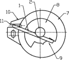
Fig. 2 is the view of locator shown in Figure 1 when assembling.
Number in the figure explanation: 1-crossbeam, the backstay that the backstay that 2-fixed axis, 3-are long, 4-are short, 5-flat front end, 6-holding section, 7-bearing, 8-end cap, 9-breach, 10-tensioning shift fork, 11-keyway.
The specific embodiment
Below in conjunction with Figure of description the utility model is elaborated.
As shown in Figure 1, locator of the present utility model is that the interposition at a crossbeam 1 installs a fixed axis 2, the position that is positioned at fixed axis 2 both sides at this crossbeam 1 is established a positioning rod 3,4 respectively, and this two backstay 3,4 and fixed axis 2 extend and parallel with fixed axis 2 to same direction.Concrete: in two backstays 3,4 is long than fixed axis 2, and another is short than fixed axis 2, and the front end 5 of a long backstay 3 is arranged to flat; Fixed axis 2 extends holding section 6 to opposite direction.Crossbeam 1 is structure as a whole with fixed axis 2 or welds together or be assembled together; Crossbeam 1 is structure as a whole with backstay 3,4 or welds together or be assembled together.
When using this locator, before the punch press riveted, end cap 8 is placed on the mandrel of bearing 7, the fixed axis 2 of locator is inserted in the endoporus of mandrel (for accurate positioning, the mandrel internal diameter that can insert with fixed axis does not rock again to good, external diameter as fixed axis is designed to the identical clearance fit relationship of reference dimension with the mandrel internal diameter), the flat front end 5 than long backstay 3 of locator is inserted in the keyway 11 of tensioning shift forks 10, an edge of the breach 9 of end cap 8 is abutted in be about to end cap 8 on another short backstay 4 of locator and decide (common, require the keyway 11 of edge of breach of end cap 8 and tensioning shift fork 10 will be point-blank) with the relative position of tensioning shift fork 10; Take away locator then, be about to end cap and mandrel riveted under the punch press drift, correct by mandrel the fixed-site of end cap and tensioning shift fork.Improve the operating efficiency of lathe and the yield rate of product thus, prevented that effectively end cap and tensioning shift fork relative position from departing from and the product rejection phenomenon.
Claims (6)
1. assemble and use locator, it is characterized in that: the interposition at a crossbeam (1) installs a fixed axis (2), the position that is positioned at described fixed axis (2) both sides at this crossbeam (1) is established a positioning rod (3,4) respectively, and this two backstay (3,4) and described fixed axis (2) extend and parallel with fixed axis (2) to same direction.
2. assembling locator according to claim 1 is characterized in that the more described fixed axis (2) in described two backstays (3,4) is long, and another more described fixed axis (2) is short.
3. assembling locator according to claim 2 is characterized in that the front end (5) of a described backstay (3) of growing is arranged to flat.
4. assembling locator according to claim 1 is characterized in that described fixed axis (2) extends holding section (6) to opposite direction.
5. assembling locator according to claim 1 is characterized in that described crossbeam (1) and fixed axis (2) are structure as a whole or weld together or be assembled together.
6. assembling locator according to claim 5 is characterized in that described crossbeam (1) and backstay (3,4) are structure as a whole or weld together or be assembled together.
Priority Applications (1)
| Application Number | Priority Date | Filing Date | Title |
|---|---|---|---|
| CN2010205766620U CN201848791U (en) | 2010-10-26 | 2010-10-26 | Assembly locator |
Applications Claiming Priority (1)
| Application Number | Priority Date | Filing Date | Title |
|---|---|---|---|
| CN2010205766620U CN201848791U (en) | 2010-10-26 | 2010-10-26 | Assembly locator |
Publications (1)
| Publication Number | Publication Date |
|---|---|
| CN201848791U true CN201848791U (en) | 2011-06-01 |
Family
ID=44091202
Family Applications (1)
| Application Number | Title | Priority Date | Filing Date |
|---|---|---|---|
| CN2010205766620U Expired - Fee Related CN201848791U (en) | 2010-10-26 | 2010-10-26 | Assembly locator |
Country Status (1)
| Country | Link |
|---|---|
| CN (1) | CN201848791U (en) |
-
2010
- 2010-10-26 CN CN2010205766620U patent/CN201848791U/en not_active Expired - Fee Related
Similar Documents
| Publication | Publication Date | Title |
|---|---|---|
| CN203003385U (en) | Inner reinforcing plate assembly fixture of rear side member | |
| CN203062169U (en) | Positioning device for assembling and welding H section steel | |
| CN202539882U (en) | Clamp for welding motorcycle frame | |
| CN201848791U (en) | Assembly locator | |
| US20090126548A1 (en) | Punch press | |
| CN203664688U (en) | Automatic cutter loosening and unloading structure of machine tool spindle | |
| CN204584704U (en) | Automobile Drive Shaft assembling special equipment | |
| CN202317575U (en) | Tube bank assembly clamping fixture | |
| CN202114496U (en) | Pneumatic fixture for boring lug holes of forks | |
| CN202508232U (en) | Entire stamping frame of bicycle | |
| CN103028879B (en) | A kind of steering drive axle assembly tooling | |
| CN202138917U (en) | Automatic locking device of flat wire winding machine | |
| CN202574344U (en) | Improved lower transmission shaft of lightweight automobile direction pipe column | |
| CN202684411U (en) | Auxiliary frame welding fixture | |
| CN202684416U (en) | Auxiliary frame welding fixture | |
| CN203184990U (en) | Vise applied to machining and positioning of nonstandard parts | |
| CN202271001U (en) | Rough and fine composite boring device for coaxial sleeve part | |
| CN102363250A (en) | Welding rod | |
| CN202291947U (en) | Welding device of drive for elevator | |
| CN202130260U (en) | Three-sectional welding rear axle | |
| CN204565706U (en) | A kind of cutting machine fixture for high pressure direct injection fuel injector | |
| CN202684373U (en) | Welding equipment | |
| CN205184349U (en) | A push up tight positioner that is used for gear shift pendulum rod wavy surface to process | |
| CN202114406U (en) | Welding rod | |
| CN202847928U (en) | Handlebar of bicycle kick scooter |
Legal Events
| Date | Code | Title | Description |
|---|---|---|---|
| C14 | Grant of patent or utility model | ||
| GR01 | Patent grant | ||
| C17 | Cessation of patent right | ||
| CF01 | Termination of patent right due to non-payment of annual fee |
Granted publication date: 20110601 Termination date: 20111026 |