The magnetic conductive media assembly that magnetic separator is used
Technical field
The utility model relates to the magnetic conductive media technical field that magnetic separator is used, the magnetic conductive media assembly that particularly a kind of magnetic separator is used.
Background technology
The strong magnetizing mediums of vertical-ring magnetic separator adopts three corrosion resistant plates as at interval at present, closely welds the magnetic conductive media bar between three block plates, forms the magnetic conductive media box.Find that in long term production there are many defectives in this magnetic conductive media box:
1) because medium strip adopts the mode of welding, so medium strip comes off from the solder joint position easily;
2) medium strip is tightr, and is when foreign material enter the medium strip slit, difficult especially clear saturating.For the foreign material in the clear saturating medium strip slit, the scene all is with things such as saw blades.When foreign material, sludge silt into one for a long time up when whole between medium strip, soak, saw blade clear saturating, whip to fall etc. and all be difficult to appear clearly.This moment, whole cartridge was just scrapped.Owing to adopt brute force saturating clearly, medium strip is out of shape, the phenomenon that wrecks especially severe simultaneously, and therefore large quantities of cartridges are scrapped;
3) medium strip is welded on the steel plate, and foreign material, sludge etc. adhere to, pile up at weld easily.Experience shows that cartridge stops up all from steel plate and medium strip weld;
4) owing to there is the steel plate of sealing to hinder the circulation of ore pulp, foreign material and current, so concentrate is mingled with manyly, and it is unclean to unload the ore deposit, and concentrate grade is low, the tailings grade height;
5) because the frequent jams of medium has been taken the free air space of ore pulp, and mine-supplying quantity does not increase, treating capacity is lower during platform.
Summary of the invention
The purpose of this utility model is for the defective of existing magnetic conductive media box, the magnetic conductive media assembly that provides a kind of full open model magnetic separator to use are provided.
The purpose of this utility model realizes by following technical proposals:
The magnetic conductive media assembly that magnetic separator of the present utility model is used, it is characterized in that by being provided with bar seam and fixing one group of magnetic conductive media plate with square hole, be located at two square hole packing rings between the magnetic conductive media plate, the square hole of this square hole packing ring and described fixing coincide with square hole, pass these square hole packing rings, two ends are provided with the connecting rod of screw thread, the hold-down nut of the two ends threaded engagement of connecting rod therewith, and the otic placode that is located at the fixedly usefulness on the top layer magnetic conductive media plate is formed.
Described magnetic conductive media plate is a monoblock magnetic conductive media plate or is formed by stacking by 2~4 blocks of dielectric-slabs, described dielectric-slab is provided with one or more groups main bar seam that is parallel to each other, when the main bar seam that is provided with that many groups are parallel to each other, each is organized and is provided with between the main bar seam and the perpendicular counterlath seam of main bar seam, also is provided with at the position of this counterlath seam and fixedly uses square hole.
The thickness of described magnetic conductive media plate is 1mm~4mm, the width of the bar seam of described magnetic conductive media plate is 1mm~4mm, retain between the bar of the described magnetic conductive media plate seam that width is arranged is the blind plate bar of 1mm~4mm, the width that two edges that described magnetic conductive media plate is provided with and main bar seam is parallel, the width at this edge equal another edge adds the width that a bar stitches.
In described one group of magnetic conductive media plate stagger mutually in the bar of adjacent two blocks of magnetic conductive media plates seam position.
Described connecting rod is a four prism type, and terminal is cylindrical near the screw thread place.
Describedly fixingly be no more than the outward flange of described square hole packing ring with the square hole size, the material of described square hole packing ring adopts stainless steel.
The fixing of described magnetic conductive media plate becomes the center symmetry status with square hole: the left side is fixing to be equated with the distance of square hole to lower limb with the right side is fixing with the distance of square hole to top edge.
The preparation method of the magnetic conductive media assembly that magnetic separator of the present utility model is used is:
1) dielectric-slab is left bar seam and fixingly use square hole, on top layer magnetic conductive media plate, is welded the fixedly otic placode of usefulness, make square hole packing ring, connecting rod,
2) replace through on the connecting rod with the square hole packing ring of making holding fixing dielectric-slab with square hole successfully, the broad edge of adjacent two blocks of dielectric-slabs places different orientation, is staggered in the bar seam position of dielectric-slab, avoids the medium lath to sew on down the phenomenon that connects,
3) reach the number of plies of installation after, the otic placode nut on the upright ring framework that is fixed to magnetic separator through tightening in the otic placode above the superiors' dielectric-slab.
Characteristics of the present utility model are:
1) avoided because medium strip adopts the mode of welding, the problem that medium strip comes off from the solder joint position easily;
2) do not adopt independent medium strip.When having avoided foreign material to enter the medium strip slit, difficult clear especially saturating problem has prolonged service life of cartridge simultaneously, has reduced production cost;
3) owing to there is not fixation steel plate, therefore avoided foreign material, sludge etc. easily in the phenomenon of weld adhesion, accumulation, medium is not easy to stop up;
4) owing to adopt full open model, not have the steel plate etc. of sealing to hinder the circulation of ore pulp, foreign material and current, so concentrate is mingled with and lack, it is clean to unload the ore deposit, has improved concentrate grade, treating capacity when having improved platform.
The utility model has solved following problem:
1) when stopping up appears in medium, as long as nut is backed out, the dielectric-slab that just can all scatter, easily clear saturating;
2) when dielectric-slab is out of shape, as long as take media set apart, just can beat gently with things such as hammers, the position of distortion is revised come;
3) owing to be to adopt independent dielectric-slab assembling, can separately stock up when therefore buying spare part.When certain a part of well damage, as long as local replacing is just passable, the possibility of having avoided whole cartridge to scrap has reduced cost;
4) owing to adopt full open model, not have the steel plate of sealing etc., so concentrate is mingled with less, it is clean to unload the ore deposit, has improved concentrate grade; Adopt the full open model media set, be not easy to stop up, be beneficial to the ore pulp circulation, certain effect is arranged reducing mine tailing;
5) this technology also can be used for the magnetic separator of other types except can being used for the slon vertical-ring magnetic separator, as imitative strong magnetic machine of Jones type and other high gradient vertical-ring magnetic separator etc.
Description of drawings
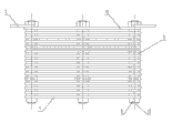
Fig. 1 is a structural representation of the present utility model.
Fig. 2 is the side view of Fig. 1.
The specific embodiment
Below in conjunction with the given embodiment of accompanying drawing, further specify the specific embodiment of the present utility model.
As shown in Figure 1, 2, the magnetic conductive media assembly that magnetic separator of the present utility model is used, it is characterized in that by being provided with bar seam and fixing one group of magnetic conductive media plate 1 with square hole 6, be located at two square hole packing rings 9 between the magnetic conductive media plate 1, the square hole of this square hole packing ring 9 and described fixingly coincide with square hole 6, pass these square hole packing rings 9, two ends are provided with the connecting rod 11 of screw thread, the hold-down nut 8 of the two ends threaded engagement of connecting rod 11 therewith, and the otic placode 2 that is located at the fixedly usefulness on the top layer magnetic conductive media plate 10 is formed.
Described magnetic conductive media plate 1 is a monoblock magnetic conductive media plate or is formed by stacking by 2~4 blocks of magnetic conductive media plates, described magnetic conductive media plate is provided with one or more groups main bar seam 4 that is parallel to each other, when being provided with main bar that many groups are parallel to each other and stitching 4, each is organized and is provided with between the main bar seam 4 and the perpendicular counterlath seam 5 of main bar seam, also is provided with at the position of this counterlath seam 5 and fixedly uses square hole.
The thickness of described magnetic conductive media plate 1 is 1mm~4mm, the width of the bar seam of described magnetic conductive media plate is 1mm~4mm, the width of retaining between the bar seam of described magnetic conductive media plate is the blind plate bar of 1mm~4mm, the width that two edges that described magnetic conductive media plate is provided with and main bar seam is parallel, the width at this edge 3 equal another edge 7 adds the width that a bar stitches.
In described one group of magnetic conductive media plate stagger mutually in the bar of adjacent two blocks of magnetic conductive media plates seam position.
Described connecting rod 11 is a four prism type, and terminal is cylindrical near the screw thread place.
Describedly fixingly be no more than the outward flange of described square hole packing ring 9 with the square hole size, the material of described square hole packing ring adopts stainless steel.
The fixing of described magnetic conductive media plate 1 becomes the center symmetry status with square hole: the left side is fixing to be equated with the distance of square hole to lower limb with the right side is fixing with the distance of square hole to top edge.
The preparation method of the magnetic conductive media assembly that magnetic separator of the present utility model is used is:
1) magnetic conductive media plate 1 is left bar seam and the fixing square hole 6 of using, on top layer magnetic conductive media plate 10, is welded the fixedly otic placode 2 of usefulness, make square hole packing ring 9, connecting rod 11,
2) replace through on the connecting rod 11 with the square hole packing ring of making 9 holding fixing magnetic conductive media plate 1 successfully with square hole 6, the broad edge of adjacent two blocks of magnetic conductive media plates places different orientation, staggered in the bar seam position of magnetic conductive media plate 1, avoid the magnetic conductive media lath to sew on down the phenomenon that connects
3) reach the number of plies of installation after, the otic placode nut on the upright ring framework that is fixed to magnetic separator through in the otic placode above the superiors' dielectric-slab 2, is tightened, nut is no more than outward flange.
The utility model has solved following problem:
1) when stopping up appears in medium, as long as nut is backed out, the medium that just can all scatter, easily clear saturating;
2) when deformation of media, as long as take medium apart, both can beat gently with things such as hammers, the position of distortion is revised come;
3) owing to be to adopt independent medium block assembling, can divide when therefore advancing spare part and drive into.When certain a part of well damage, as long as local replacing is just passable, the possibility of having avoided the monoblock medium to scrap has reduced cost;
4) owing to adopt full open model, not have the steel plate of sealing etc., so concentrate is mingled with less, it is clean to unload the ore deposit, has improved concentrate grade; Adopt the full open model dielectric-slab, be not easy to stop up, be beneficial to the ore pulp circulation, certain effect is arranged reducing mine tailing.