CN201848135U - Quick-changing cartridge filter - Google Patents
Quick-changing cartridge filter Download PDFInfo
- Publication number
- CN201848135U CN201848135U CN2010205538728U CN201020553872U CN201848135U CN 201848135 U CN201848135 U CN 201848135U CN 2010205538728 U CN2010205538728 U CN 2010205538728U CN 201020553872 U CN201020553872 U CN 201020553872U CN 201848135 U CN201848135 U CN 201848135U
- Authority
- CN
- China
- Prior art keywords
- filter core
- gland
- quick
- unsteady gland
- guide plate
- Prior art date
- Legal status (The legal status is an assumption and is not a legal conclusion. Google has not performed a legal analysis and makes no representation as to the accuracy of the status listed.)
- Expired - Lifetime
Links
- 210000004907 gland Anatomy 0.000 claims description 90
- 230000008878 coupling Effects 0.000 claims description 4
- 238000010168 coupling process Methods 0.000 claims description 4
- 238000005859 coupling reaction Methods 0.000 claims description 4
- 230000005540 biological transmission Effects 0.000 abstract 5
- 238000009434 installation Methods 0.000 description 7
- 230000000694 effects Effects 0.000 description 3
- 238000005516 engineering process Methods 0.000 description 3
- 238000010586 diagram Methods 0.000 description 2
- 238000000926 separation method Methods 0.000 description 2
- 125000006850 spacer group Chemical group 0.000 description 2
- 230000009286 beneficial effect Effects 0.000 description 1
- 238000006243 chemical reaction Methods 0.000 description 1
- 238000004140 cleaning Methods 0.000 description 1
- 239000003814 drug Substances 0.000 description 1
- 238000004043 dyeing Methods 0.000 description 1
- 238000001914 filtration Methods 0.000 description 1
- 239000012467 final product Substances 0.000 description 1
- 239000012530 fluid Substances 0.000 description 1
- 239000007788 liquid Substances 0.000 description 1
- 238000005272 metallurgy Methods 0.000 description 1
- 238000000034 method Methods 0.000 description 1
- 239000003921 oil Substances 0.000 description 1
- 239000003973 paint Substances 0.000 description 1
- 238000007747 plating Methods 0.000 description 1
- 238000007639 printing Methods 0.000 description 1
- 238000000746 purification Methods 0.000 description 1
- 239000007787 solid Substances 0.000 description 1
- 239000000126 substance Substances 0.000 description 1
- 239000000758 substrate Substances 0.000 description 1
- XLYOFNOQVPJJNP-UHFFFAOYSA-N water Substances O XLYOFNOQVPJJNP-UHFFFAOYSA-N 0.000 description 1
- 238000009941 weaving Methods 0.000 description 1
- 238000004804 winding Methods 0.000 description 1
Images


Landscapes
- Filtration Of Liquid (AREA)
Abstract
The utility model discloses a quick-changing cartridge filter which comprises a tank body, a separating plate and filter cartridges, wherein the separating plate is provided with fixing holes; the filter cartridges are respectively fixed in the fixing holes of the separating plate by a locking mechanism; the locking mechanism comprises a hand wheel, a transmission rod and a movable component, wherein the upper end of the transmission rod is fixed at a middle shaft of the hand wheel; the transmission rod is connected with the movable component, and the movable component is driven to move along the axial direction by the transmission rod; the movable component comprises a floating press sleeve guide plate and at least one floating press sleeve; the floating press sleeve guide plate is driven to make linear motion along the axial direction of the transmission rod; the inner wall of the floating press sleeve is provided with at least two support clamping blocks and clamping grooves in a convex way; one ends of the filter cartridges are provided with filter cartridge joints which are inserted into the floating press sleeve; the outer walls of the filter cartridge joints are provided with convex blocks in a convex way, and the convex blocks are clamped with the clamping grooves; the filter cartridge joints pass through the floating press sleeve downwards; and after being rotated, the convex blocks of the filter cartridge joints can be clamped at the lower ends of the support clamping blocks of the floating press sleeve. The quick-changing cartridge filter is simple and convenient to replace the filter cartridges, thus greatly improving the efficiency of disassembling and assembling the filter cartridges.
Description
Technical field
The utility model relates to a kind of filtering separation device, relates in particular to a kind of quick-changing type candle filter.
Background technology
Candle filter is a kind of Multifunction filter, has been widely used in the Separation of Solid and Liquid in the industries such as fluid purifications such as water, oil, paint and machinery, metallurgy, chemical industry, weaving, printing and dyeing, plating, medicine, food.
Application number is that 00267003.8 Chinese patent discloses a kind of candle filter, comprise a tank body and the end cap that is positioned at the tank body two ends, be provided with filter body in the tank body, filter body comprises filter core, realizes the fixing of filter core on the demarcation strip in the tank body thereby described filter core is screwed onto by screw thread, so when needs are changed the filter core that has stopped up, the end cap of only need outwarding winding unscrews filter core and takes out demarcation strip, and then takes out old filter core, change new filter core, screw end cap again and get final product.
Yet when relating to the fixing and demolition of many filter cores, because filter core is distributed in tank interior, the restriction that setting tool (as spanner) is subjected to the space is difficult to put to good use, brings very big inconvenience, influence dismounting and installation effectiveness so for the operation of dismounting and installation filter core.
The utility model content
The technical problem that the utility model mainly solves provides a kind of quick-changing type candle filter, and dismounting and installation filter core are all simple, convenient, fast.
For solving the problems of the technologies described above, the technical scheme that the utility model adopts is: a kind of quick-changing type candle filter is provided, comprise a tank body, be arranged in the horizontally disposed demarcation strip of tank body, and the filter core that is arranged in tank body, the lower end of described filter core is fixed on the described demarcation strip, it is characterized in that: described demarcation strip is provided with and the fixing fixing hole of described filter core, and described filter core is fixed on by a retaining mechanism in the fixing hole of described demarcation strip, and described retaining mechanism comprises:
Handwheel;
With the drive link that described filter core be arranged in parallel, the drive link upper end is fixed on the described handwheel axis;
With the moving assembly that described drive link is connected, described moving assembly is driven along the axial direction of drive link by described drive link and moves;
Described moving assembly comprises a unsteady gland guide plate and an at least one unsteady gland, described unsteady gland guide plate is positioned at the demarcation strip top and be arranged in parallel with described demarcation strip, offer on the described unsteady gland guide plate and corresponding first locating hole of described unsteady gland, described unsteady gland is inserted in described first locating hole from top to bottom, described drive link drives described unsteady gland guide plate along the axial moving linearly of drive link, convex with the fixture block that balances or cancel each other at least on the described unsteady gland inwall, adjacent balancing or cancel each other is recessed to form draw-in groove between the fixture block, one end of described filter core is provided with the filter core joint, described filter core joint is inserted in the described unsteady gland, convex with the projection that fastens with described draw-in groove on the outer wall of described filter core joint, described filter core joint can pass unsteady gland downwards, and the postrotational projection of filter core joint may be stuck in the gland that floats and supports the fixture block lower end.
Wherein, described moving assembly comprises a moving press plate, and described moving press plate and described demarcation strip be arranged in parallel, and described moving press plate is positioned at the top of described unsteady gland guide plate, the center of described moving press plate is provided with a feed screw nut, and described feed screw nut is driven by described drive link and does axially-movable.
Wherein, convex with screw mandrel on the described unsteady gland guide plate, be connected by a shaft coupling between screw mandrel and the described drive link.
Wherein, be provided with stage clip between described moving press plate and the described unsteady gland guide plate, described stage clip is positioned at described unsteady gland.
Wherein, offer a plurality of first through holes on the described moving press plate, described first through hole is corresponding with described first locating hole, described moving assembly also comprises spring press-cover, the butt ring that described spring press-cover has a sleeve and is connected with sleeve one end periphery, described sleeve is inserted in described first through hole and is connected on the described stage clip, described butt ring is connected on the surface of described moving press plate, described filter core joint is inserted in the sleeve of described spring press-cover and is pressed on the described stage clip, one end of described unsteady gland is set in the described sleeve, and the other end is plugged in described first locating hole.
Wherein, described moving press plate is provided with the hollow reference column, and described unsteady gland guide plate is provided with the axis of guide, and an end of the described axis of guide is inserted in the described hollow reference column.
Wherein, described demarcation strip is provided with the 3rd locating hole, and the described axis of guide runs through described unsteady gland guide plate vertically, and the other end of the described axis of guide is plugged in described the 3rd locating hole.
Wherein, offer the 4th locating hole on the described unsteady gland guide plate, convex with alignment pin on the described demarcation strip, described alignment pin is inserted in described the 4th locating hole.
Wherein, described is four to the fixture block number, is symmetricly set on the inwall of described unsteady gland, and the projection number on the described filter core joint is four, and is symmetrical arranged.
Wherein, described is two to the fixture block number, is symmetricly set on the inwall of described unsteady gland, and described projection number is two, is symmetricly set on the filter core joint.
The beneficial effects of the utility model are: the filter core that is different from prior art is to be screwed onto in the tank body by screw thread, when relating to the fixing and demolition of many filter cores, the restriction that setting tool is subjected to the space is difficult to put to good use, brings the situation of very big inconvenience and influence dismounting and installation effectiveness so for the operation of dismantling and installing filter core.The utility model drives drive link by rotation hand wheel and rotates, drive link drive to float gland guide plate and the gland that floats together along the axial moving linearly of drive link, become flexible between gland and the described filter core joint thereby making floats, manually rotate filter core then, filter core can be taken out; And when needs are fastening again with filter core, only the filter core joint need be inserted in the gland that floats, hand-held filter core rotates to an angle, and then reverse rotation handwheel, drive the to float projection that fixture block presses described filter core joint that supports of gland of drive link fastens, thereby make filter core and described unsteady gland fastening, so more the renew cartridge operation is all simple and convenient, can improve the efficient that removes and installs of filter core greatly.
Description of drawings
Fig. 1 is the schematic cross-section of the utility model quick-changing type candle filter;
Fig. 2 is the enlarged drawing of A part in the utility model quick-changing type candle filter among Fig. 1;
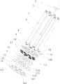
Fig. 3 is the exploded view after the utility model quick-changing type candle filter is removed tank body;
Fig. 4 is the filter core joint stereogram of the utility model quick-changing type candle filter;
Fig. 5 is the unsteady gland stereogram of the utility model quick-changing type candle filter;
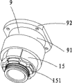
Fig. 6 is the filter core joint of the utility model quick-changing type candle filter, the installation diagram of float gland and spring press-cover;
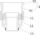
Fig. 7 is a filter core joint among Fig. 6, the sectional view of the installation diagram of float gland and spring press-cover.
The specific embodiment
By describing technology contents of the present utility model, structural feature in detail, realized purpose and effect, give explanation below in conjunction with embodiment and conjunction with figs. are detailed.
See also Fig. 1, Fig. 2 and Fig. 3, the utility model quick-changing type candle filter comprises a tank body 4, is positioned at the end cap 1 of tank body 4 upper and lower ends, is arranged in tank body 4 horizontally disposed demarcation strips 14, and is arranged in a plurality of inclinations of tank body 4 or vertical filter core 5.The upper end of described filter core is fixed on the described demarcation strip 14.Described demarcation strip 14 is provided with the fixing hole of fixing with described filter core 5 141, and described filter core 5 is fixed in the fixing hole 141 of described demarcation strip 14 by a retaining mechanism.
See also Fig. 4 to Fig. 7, described retaining mechanism comprises a handwheel 2, drive link 3 and moving assembly, and an end of described drive link 3 is connected with the axis of described handwheel 2 and be arranged in parallel with described filter core 5; Described moving assembly is connected with described drive link 3, and by the axial direction moving linearly of described drive link 3 drives along drive link 3; Described moving assembly is connected with described demarcation strip 14.
Described moving assembly comprises a unsteady gland guide plate 13 and an at least one unsteady gland 12, described unsteady gland guide plate 13 be arranged in parallel with described demarcation strip 14, offer on the described unsteady gland guide plate 13 and described unsteady gland 12 corresponding first locating holes 131, described unsteady gland 12 is inserted in described first locating hole 131 from top to bottom, described drive link 3 drives the axial moving linearly of described unsteady gland guide plate 13 along drive link 3, thereby drive described unsteady gland 12 moving linearly vertically together, convex with the fixture block 121 that balances or cancel each other at least on described unsteady gland 12 inwalls, adjacent balancing or cancel each other is recessed to form draw-in groove 122 between the fixture block 121, one end of described filter core is provided with filter core joint 15, described filter core joint 15 is inserted in the described unsteady gland 12, convexes with the projection 151 that fastens with described draw-in groove 122 on the outer wall of described filter core joint 15.Described filter core joint 15 can pass the gland 12 that floats downwards, and filter core joint 15 postrotational projections 151 may be stuck in the lower end that the gland that floats supports fixture block 121.
When the utility model quick-changing type candle filter breaks down needs replacing or cleaning at filter core 5, only need open the end cap 1 of tank body 4 upper ends, rotation hand wheel 2 drives drive link 3 and rotates, drive link 3 makes to float and becomes flexible between gland 12 and the described filter core joint 15, manually rotate filter core then, filter core 5 can be taken out; And when needs retighten filter core 5, only filter core 5 joints need be inserted in the gland 12 that floats, hand-held filter core rotates to an angle, and then reverse rotation handwheel 2, the projection 151 that fixture block presses described filter core joint 15 that supports that drive link 3 drives the gland 12 that floats fastens, thereby makes filter core 5 fastening with described unsteady gland 12.
Please continue to consult Fig. 3, in the present embodiment, described moving assembly comprises a moving press plate 10, described moving press plate 10 be arranged in parallel with described demarcation strip 14, the center of described moving press plate 10 is connected with a feed screw nut 8, described feed screw nut 8 is driven by described drive link 3 and does axially-movable, and the described moving press plate 10 of described feed screw nut 8 drives is done axially-movable together.
Described moving assembly also comprises a unsteady gland guide plate 13, described unsteady gland guide plate 13 be arranged in parallel with described moving press plate 10, described unsteady gland guide plate 13 centers are provided with a screw mandrel 7, and described screw mandrel 7 runs through described feed screw nut 8 and is connected by a shaft coupling 6 with described drive link 3.Described feed screw nut 8 drives described screw mandrel 7 and drives described unsteady gland guide plate 13 together along screw mandrel 7 axial moving linearlies by shaft coupling 6.
Offer a plurality of first through holes 101 on the described moving press plate 10, first locating hole 131 that offers on described first through hole 101 and the described unsteady gland guide plate 13 is corresponding.Be provided with stage clip 11 between described moving press plate 10 and the described unsteady gland guide plate 13, described stage clip 11 is positioned at described unsteady gland 12.Described moving assembly also comprises spring press-cover 9, and the butt ring 92 that described spring press-cover 9 has a sleeve 91 and is connected with sleeve 91 1 end peripheries, described sleeve 91 are inserted in described first through hole 101 and are connected on the described stage clip 11.One end of described unsteady gland 12 is set in the described sleeve 91, and the other end is inserted in described first locating hole 131.Described butt ring 92 is connected on the surface of described moving press plate 10, and described filter core joint 15 is inserted in the sleeve 91 of described spring press-cover 9 and is pressed on the described stage clip 11.
Described moving press plate 10 is provided with hollow reference column 102, described unsteady gland guide plate 13 is provided with the axis of guide 132, one end of the described axis of guide 132 is inserted in the described hollow reference column 102, thereby to playing the effect of guide-localization between moving press plate 10 and the unsteady gland guide plate 13.
Described demarcation strip 14 is provided with the 3rd locating hole 142, and the described axis of guide 132 runs through described unsteady gland guide plate 13 vertically, and the other end of the described axis of guide 132 is plugged in described the 3rd locating hole 142.
Offer the 4th locating hole 133 on the described unsteady gland guide plate 13, convex with alignment pin 145 on the described demarcation strip 14, described alignment pin 145 is inserted in described the 4th locating hole 133.
When filter core generation fault causes filter to filter inefficacy, stop up or breakage such as filter core, the filter core that needs to break down takes out when dealing with and (cleans or renewal), only need open the end cap 1 of tank body 4 upper ends, rotation hand wheel 2 drives drive link 3 and rotates, drive link 3 makes to float and becomes flexible between gland 12 and the described filter core joint 15, manually rotates filter core then, filter core 5 can be taken out; And when needs retighten filter core 5, only filter core 5 joints need be inserted in the gland 12 that floats, hand-held filter core rotates to an angle, and then reverse rotation handwheel 2, the projection 151 that fixture block presses described filter core joint 15 that supports that drive link 3 drives the gland 12 that floats fastens, thereby makes filter core 5 fastening with described unsteady gland 12.
In the present embodiment, in the gland 12 that floats is four to fixture block, and on the inwall that is arranged on described unsteady gland 12 of symmetry, the projection on the described filter core joint 5 is four, is symmetrical arranged respectively; So, described filter core rotation 45 degree can take out filter core or be fastening.
Among another embodiment, described be arranged on gland 12 inwalls that float to support fixture block can also be two, and be symmetrical arranged, projection on the described filter core joint 5 is two, be symmetrical arranged, described operation principle is identical with the foregoing description substrate, and difference is described filter core revolved to turn 90 degrees filter core to be taken out or fastening.
The filter core that is different from prior art is to be screwed onto in the tank body by screw thread, when relating to the fixing and demolition of many filter cores, the restriction that setting tool is subjected to the space is difficult to put to good use, brings the situation of very big inconvenience and influence dismounting and installation effectiveness so for the operation of dismantling and installing filter core.The utility model drives drive link 3 by rotation hand wheel 2 and rotates, and drive link 3 makes to float and becomes flexible between gland 12 and the described filter core joint 15, manually rotates filter core then, filter core 5 can be taken out; And when needs retighten filter core 5, only filter core 5 joints need be inserted in the gland 12 that floats, hand-held filter core rotates to an angle, and then reverse rotation handwheel 2, the projection 151 that fixture block presses described filter core joint 15 that supports that drive link 3 drives the gland 12 that floats fastens, thereby make filter core 5 and described unsteady gland 12 fastening, so more the renew cartridge operation is all simple and convenient, can improve the efficient that removes and installs of filter core greatly.
The above only is embodiment of the present utility model; be not so limit claim of the present utility model; every equivalent structure or equivalent flow process conversion that utilizes the utility model specification and accompanying drawing content to be done; or directly or indirectly be used in other relevant technical fields, all in like manner be included in the scope of patent protection of the present utility model.
Claims (10)
1. quick-changing type candle filter, comprise a tank body, be arranged in the horizontally disposed demarcation strip of tank body, and the filter core that is arranged in tank body, the lower end of described filter core is fixed on the described demarcation strip, it is characterized in that: described demarcation strip is provided with and the fixing fixing hole of described filter core, described filter core is fixed on by a retaining mechanism in the fixing hole of described demarcation strip, and described retaining mechanism comprises:
Handwheel;
With the drive link that described filter core be arranged in parallel, the drive link upper end is fixed on the described handwheel axis;
With the moving assembly that described drive link is connected, described moving assembly is driven along the axial direction of drive link by described drive link and moves;
Described moving assembly comprises a unsteady gland guide plate and an at least one unsteady gland, described unsteady gland guide plate is positioned at the demarcation strip top and be arranged in parallel with described demarcation strip, offer on the described unsteady gland guide plate and corresponding first locating hole of described unsteady gland, described unsteady gland is inserted in described first locating hole from top to bottom, described drive link drives described unsteady gland guide plate along the axial moving linearly of drive link, convex with the fixture block that balances or cancel each other at least on the described unsteady gland inwall, adjacent balancing or cancel each other is recessed to form draw-in groove between the fixture block, one end of described filter core is provided with the filter core joint, described filter core joint is inserted in the described unsteady gland, convex with the projection that fastens with described draw-in groove on the outer wall of described filter core joint, described filter core joint can pass unsteady gland downwards, and the postrotational projection of filter core joint may be stuck in the gland that floats and supports the fixture block lower end.
2. quick-changing type candle filter according to claim 1, it is characterized in that: described moving assembly comprises a moving press plate, described moving press plate and described demarcation strip be arranged in parallel, described moving press plate is positioned at the top of described unsteady gland guide plate, the center of described moving press plate is provided with a feed screw nut, and described feed screw nut is driven by described drive link and does axially-movable.
3. quick-changing type candle filter according to claim 1 is characterized in that: convex with screw mandrel on the described unsteady gland guide plate, be connected by a shaft coupling between screw mandrel and the described drive link.
4. quick-changing type candle filter according to claim 3 is characterized in that: be provided with stage clip between described moving press plate and the described unsteady gland guide plate, described stage clip is positioned at described unsteady gland.
5. quick-changing type candle filter according to claim 4, it is characterized in that: offer a plurality of first through holes on the described moving press plate, described first through hole is corresponding with described first locating hole, described moving assembly also comprises spring press-cover, the butt ring that described spring press-cover has a sleeve and is connected with sleeve one end periphery, described sleeve is inserted in described first through hole and is connected on the described stage clip, described butt ring is connected on the surface of described moving press plate, described filter core joint is inserted in the sleeve of described spring press-cover and is pressed on the described stage clip, one end of described unsteady gland is set in the described sleeve, and the other end is plugged in described first locating hole.
6. quick-changing type candle filter according to claim 5 is characterized in that: described moving press plate is provided with the hollow reference column, and described unsteady gland guide plate is provided with the axis of guide, and an end of the described axis of guide is inserted in the described hollow reference column.
7. quick-changing type candle filter according to claim 6 is characterized in that: described demarcation strip is provided with the 3rd locating hole, and the described axis of guide runs through described unsteady gland guide plate vertically, and the other end of the described axis of guide is plugged in described the 3rd locating hole.
8. according to claim 6 or 7 described quick-changing type candle filters, it is characterized in that: offer the 4th locating hole on the described unsteady gland guide plate, convex with alignment pin on the described demarcation strip, described alignment pin is inserted in described the 4th locating hole.
9. quick-changing type candle filter according to claim 8 is characterized in that: described is four to the fixture block number, is symmetricly set on the inwall of described unsteady gland, and the projection number on the described filter core joint is four, and is symmetrical arranged.
10. quick-changing type candle filter according to claim 8 is characterized in that: described is two to the fixture block number, is symmetricly set on the inwall of described unsteady gland, and described projection number is two, is symmetricly set on the filter core joint.
Priority Applications (1)
| Application Number | Priority Date | Filing Date | Title |
|---|---|---|---|
| CN2010205538728U CN201848135U (en) | 2010-10-09 | 2010-10-09 | Quick-changing cartridge filter |
Applications Claiming Priority (1)
| Application Number | Priority Date | Filing Date | Title |
|---|---|---|---|
| CN2010205538728U CN201848135U (en) | 2010-10-09 | 2010-10-09 | Quick-changing cartridge filter |
Publications (1)
| Publication Number | Publication Date |
|---|---|
| CN201848135U true CN201848135U (en) | 2011-06-01 |
Family
ID=44090550
Family Applications (1)
| Application Number | Title | Priority Date | Filing Date |
|---|---|---|---|
| CN2010205538728U Expired - Lifetime CN201848135U (en) | 2010-10-09 | 2010-10-09 | Quick-changing cartridge filter |
Country Status (1)
| Country | Link |
|---|---|
| CN (1) | CN201848135U (en) |
Cited By (12)
| Publication number | Priority date | Publication date | Assignee | Title |
|---|---|---|---|---|
| CN101972562A (en) * | 2010-10-09 | 2011-02-16 | 深圳市森科妍科技有限公司 | Filter with rapidly-replaced filter element |
| CN103316518A (en) * | 2013-07-18 | 2013-09-25 | 浙江方明塑胶管道有限公司 | Precision filter |
| CN103446810A (en) * | 2013-08-19 | 2013-12-18 | 常熟市上海飞奥压力容器制造有限公司 | Natural gas filter |
| CN104096398A (en) * | 2014-07-28 | 2014-10-15 | 苏州台合达环保设备有限公司 | Filtration barrel |
| CN105032048A (en) * | 2015-07-31 | 2015-11-11 | 俞升洋 | Waste gas treatment device with valve |
| CN105107256A (en) * | 2015-08-04 | 2015-12-02 | 达格玛(厦门)环保科技有限公司 | Conveniently assembled and disassembled water purifier |
| CN107684766A (en) * | 2016-07-05 | 2018-02-13 | 胡玥 | A kind of parallel ceramic water purification apparatus of more filter cores |
| CN109794114A (en) * | 2017-11-16 | 2019-05-24 | 崇鸣投资有限公司 | Unsupported filter including multiple built-in filter tubes and filter assembly composed of the filter |
| CN110416575A (en) * | 2019-07-31 | 2019-11-05 | 吴与琛 | A kind of new-energy automobile fuel cell filter assemblies |
| CN110779195A (en) * | 2019-10-18 | 2020-02-11 | 河南中烟工业有限责任公司 | Air conditioner dust removal filter cartridge support |
| CN111035982A (en) * | 2018-10-12 | 2020-04-21 | 中国石油天然气股份有限公司 | oil filter |
| CN120305751A (en) * | 2025-06-16 | 2025-07-15 | 山西鑫海环境治理股份有限公司 | Waste oil treatment decolorization device and decolorization method |
-
2010
- 2010-10-09 CN CN2010205538728U patent/CN201848135U/en not_active Expired - Lifetime
Cited By (18)
| Publication number | Priority date | Publication date | Assignee | Title |
|---|---|---|---|---|
| CN101972562B (en) * | 2010-10-09 | 2012-10-03 | 深圳市森科妍科技有限公司 | Filter with rapidly-replaced filter element |
| CN101972562A (en) * | 2010-10-09 | 2011-02-16 | 深圳市森科妍科技有限公司 | Filter with rapidly-replaced filter element |
| CN103316518B (en) * | 2013-07-18 | 2016-04-13 | 浙江方明塑胶管道有限公司 | A kind of accurate filter |
| CN103316518A (en) * | 2013-07-18 | 2013-09-25 | 浙江方明塑胶管道有限公司 | Precision filter |
| CN103446810A (en) * | 2013-08-19 | 2013-12-18 | 常熟市上海飞奥压力容器制造有限公司 | Natural gas filter |
| CN104096398A (en) * | 2014-07-28 | 2014-10-15 | 苏州台合达环保设备有限公司 | Filtration barrel |
| CN104096398B (en) * | 2014-07-28 | 2016-01-20 | 苏州台合达环保设备有限公司 | A kind of filter cylinder |
| CN105032048A (en) * | 2015-07-31 | 2015-11-11 | 俞升洋 | Waste gas treatment device with valve |
| CN105107256A (en) * | 2015-08-04 | 2015-12-02 | 达格玛(厦门)环保科技有限公司 | Conveniently assembled and disassembled water purifier |
| CN107684766A (en) * | 2016-07-05 | 2018-02-13 | 胡玥 | A kind of parallel ceramic water purification apparatus of more filter cores |
| CN107684766B (en) * | 2016-07-05 | 2018-08-28 | 惠州市沃特科尔电器有限公司 | A kind of parallel ceramic water purification apparatus of more filter cores |
| CN109794114A (en) * | 2017-11-16 | 2019-05-24 | 崇鸣投资有限公司 | Unsupported filter including multiple built-in filter tubes and filter assembly composed of the filter |
| CN109794114B (en) * | 2017-11-16 | 2021-09-17 | 崇鸣投资有限公司 | Unsupported filter comprising a plurality of built-in filter tubes and filter assembly comprising such a filter |
| CN111035982A (en) * | 2018-10-12 | 2020-04-21 | 中国石油天然气股份有限公司 | oil filter |
| CN110416575A (en) * | 2019-07-31 | 2019-11-05 | 吴与琛 | A kind of new-energy automobile fuel cell filter assemblies |
| CN110779195A (en) * | 2019-10-18 | 2020-02-11 | 河南中烟工业有限责任公司 | Air conditioner dust removal filter cartridge support |
| CN110779195B (en) * | 2019-10-18 | 2022-01-11 | 河南中烟工业有限责任公司 | Air conditioner dust removal filter cartridge support |
| CN120305751A (en) * | 2025-06-16 | 2025-07-15 | 山西鑫海环境治理股份有限公司 | Waste oil treatment decolorization device and decolorization method |
Similar Documents
| Publication | Publication Date | Title |
|---|---|---|
| CN201848135U (en) | Quick-changing cartridge filter | |
| CN101972562B (en) | Filter with rapidly-replaced filter element | |
| CN104258612B (en) | A kind of water purifier of fast changeable filter core | |
| KR20120114848A (en) | High purity distillation apparatus of continuous type | |
| CN104128027B (en) | A backwash laminated filter | |
| CN104248871B (en) | A kind of water purifier filter element component of fast changeable | |
| CN216725977U (en) | Waste water filtering device convenient to change and keep apart filter screen | |
| CN212107000U (en) | High-strength composite core valve | |
| CN200951349Y (en) | Filtration element | |
| CN204147884U (en) | A kind of ion exchange resin column of improvement | |
| CN113351151B (en) | Design method of suspension type eccentric downcomer float valve tower plate | |
| CN213467763U (en) | Efficient material recycling circulation tank | |
| CN107973363A (en) | A kind of packaging type removal of heavy metal ions device and its adsorbing sphere installation method | |
| CN211302250U (en) | Filter element mounting structure of household water purifier | |
| CN202654785U (en) | Filtering device of oil-water separator | |
| CN221093859U (en) | DTRO membrane module convenient to dismouting | |
| CN213159453U (en) | High mass transfer efficiency bubble cap trays | |
| CN216654095U (en) | Novel one-level reverse osmosis equipment | |
| CN222540504U (en) | A water treatment filter bottle | |
| CN214286930U (en) | Stainless steel folding filter element | |
| CN116688613A (en) | Metal filter element convenient to change | |
| CN220370573U (en) | Filtering device for lubricating oil tank | |
| CN221618741U (en) | Pressure pipeline filter | |
| CN219481760U (en) | Bundling filter | |
| CN212327803U (en) | Harmful gas treatment equipment for plastic pellet production |
Legal Events
| Date | Code | Title | Description |
|---|---|---|---|
| C14 | Grant of patent or utility model | ||
| GR01 | Patent grant | ||
| AV01 | Patent right actively abandoned |
Granted publication date: 20110601 Effective date of abandoning: 20121003 |