CN201848131U - Table-flap type multi-stage mud-discharge settling tank applied to sewage treatment - Google Patents
Table-flap type multi-stage mud-discharge settling tank applied to sewage treatment Download PDFInfo
- Publication number
- CN201848131U CN201848131U CN201020582708XU CN201020582708U CN201848131U CN 201848131 U CN201848131 U CN 201848131U CN 201020582708X U CN201020582708X U CN 201020582708XU CN 201020582708 U CN201020582708 U CN 201020582708U CN 201848131 U CN201848131 U CN 201848131U
- Authority
- CN
- China
- Prior art keywords
- pond
- tank
- mud
- water
- flap
- Prior art date
- Legal status (The legal status is an assumption and is not a legal conclusion. Google has not performed a legal analysis and makes no representation as to the accuracy of the status listed.)
- Expired - Lifetime
Links
- 239000010865 sewage Substances 0.000 title claims abstract description 19
- XLYOFNOQVPJJNP-UHFFFAOYSA-N water Substances O XLYOFNOQVPJJNP-UHFFFAOYSA-N 0.000 claims abstract description 33
- 239000010802 sludge Substances 0.000 claims abstract description 24
- 238000004062 sedimentation Methods 0.000 claims description 30
- VYPSYNLAJGMNEJ-UHFFFAOYSA-N Silicium dioxide Chemical compound O=[Si]=O VYPSYNLAJGMNEJ-UHFFFAOYSA-N 0.000 claims description 26
- 239000000377 silicon dioxide Substances 0.000 claims description 13
- 230000000694 effects Effects 0.000 abstract description 7
- 238000007790 scraping Methods 0.000 abstract description 6
- 239000002893 slag Substances 0.000 abstract 3
- 238000011900 installation process Methods 0.000 abstract 1
- 238000010586 diagram Methods 0.000 description 4
- 239000000725 suspension Substances 0.000 description 4
- 238000005516 engineering process Methods 0.000 description 3
- 238000000034 method Methods 0.000 description 3
- 238000001556 precipitation Methods 0.000 description 2
- 230000009286 beneficial effect Effects 0.000 description 1
- 238000004140 cleaning Methods 0.000 description 1
- 238000000975 co-precipitation Methods 0.000 description 1
- 238000010276 construction Methods 0.000 description 1
- 230000001186 cumulative effect Effects 0.000 description 1
- 239000003344 environmental pollutant Substances 0.000 description 1
- 238000009434 installation Methods 0.000 description 1
- 231100000719 pollutant Toxicity 0.000 description 1
- 230000002035 prolonged effect Effects 0.000 description 1
- 230000000630 rising effect Effects 0.000 description 1
- 239000010801 sewage sludge Substances 0.000 description 1
Images
Landscapes
- Sewage (AREA)
Abstract
The utility model discloses a table-flap type multi-stage mud-discharge settling tank applied to sewage treatment. The table-flap type multi-stage mud-discharge settling tank comprises a tank body; a water inlet strobe and a water outlet are arranged on the tank body; a water distribution porous plate, a mud scraping machine, a slag removing pipe and a water collecting tank are sequentially arranged in the tank body from the water inlet strobe to the water outlet; the slag removing pipe is connected with a floating slag well which is provided with a sewage drainage pipe; a plurality of sludge hoppers are arranged at the bottom of the tank body; the surface of the tank bottom is horizontal; the tank body is internally provided with a plurality of table-flaps with the length the same as the width of the tank body; the plurality of table-flaps are arranged at two height positions close to the tank top and the tank bottom and are arranged along the water flow direction; and the table-flaps close to the tank top and the table-flaps close to the tank bottom are arranged in a staggered manner. The table-flap type multi-stage mud-discharge settling tank solves the technical problem that the sludge at an inlet of the traditional parallel flow type settling tank floats up; the treatment effect can be improved; and the electric consumption of the mud scraping machine can be reduced. Simultaneously the difficulty of the mud scraping equipment can be lightened during the installation process.
Description
Technical field
The utility model relates to a kind of sewage treatment plant rectangular sedimentation tank, relates in particular to a kind of multistage spoil disposal sedimentation basin.
Background technology
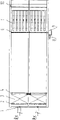
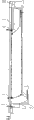
Rectangular sedimentation tank is the form that preliminary sedimentation tank more often adopts, and is used for separating the sewage suspension.Its basic structure as depicted in figs. 1 and 2, the pond body is provided with inlet gate 1 and delivery port 10; Be provided with water distribution orifice plate 2, chain-plate type mud scraper 4, skimming pipe 6 and water leg 7 from described inlet gate 1 successively between the described delivery port 10 in the body of described pond; Described skimming pipe 6 is connected to a scum silica frost well 9, described scum silica frost well 9 is provided with effluent outfall 8, described pond basal surface is the inclined-plane with vertical waviness, establish sludge bucket 11 in the bottom of sedimentation basin porch, the sewage bottom horizontal flow sheet, chain-plate type mud scraper 4 is advanced to inlet from pond body delivery port 10, promptly as shown in Figure 2, the chain that has cleaning shoe turns round along clockwise direction, along with the operation of mud scraper, mud is scraped to sludge bucket 11.Find that in actual motion there are the following problems for traditional rectangular sedimentation tank: 1. when the water inlet suspension content was high, the pollutant burden of pond body was higher, and treatment effect is not satisfactory; 2. drain into the bucket that inlet is handled setting because mud is concentrated, have mud come-up problem in the porch; 3. in the process that inlet is advanced, sludge quantity can be cumulative from outlet for mud scraper, and to having relatively high expectations of mud scraper, power consumption in service is bigger.
The utility model content
At above-mentioned prior art, the utility model provides a kind of multistage spoil disposal sedimentation basin of folded plate type that is applied in the sewage disposal.The utility model has solved the technical problem of the mud come-up of traditional rectangular sedimentation tank porch existence, can improve treatment effect, has reduced the power consumption of mud scraper.Simultaneously, also alleviated difficulty when scraping mud equipment and installing.
In order to solve the problems of the technologies described above, the technical scheme that a kind of multistage spoil disposal sedimentation basin of folded plate type that is applied in the sewage disposal of the utility model is achieved is: comprise the pond body, described pond body is provided with inlet gate and delivery port; Be provided with water distribution orifice plate, mud scraper, skimming pipe and water leg from described inlet gate successively between the described delivery port in the body of described pond; Described skimming pipe is connected to a scum silica frost well, and described scum silica frost well is provided with effluent outfall; Body bottom, described pond is provided with sludge bucket, and described pond basal surface is for being horizontally disposed with; Described sludge bucket is a plurality of; Be provided with the identical flap of width of a plurality of its length and described pond body in the body of described pond; Described a plurality of flap is distributed near Chi Ding with near arranging on two height and positions at the bottom of the pond and along water (flow) direction, is staggered near the flap of Chi Ding with near the flap at the bottom of the pond.
Compared with prior art, the beneficial effects of the utility model are: because the utility model sedimentation basin is provided with the flap that can realize multistage spoil disposal function, prolonged the distance of effluent stream warp in the pond, also good sedimentation effect can be arranged when suspension content is higher, (along water (flow) direction) establishes a plurality of sludge buckets to the exit from body porch, pond, and the mud of precipitation can in time be drained.Therefore, overcome the technical problem of the mud come-up of traditional rectangular sedimentation tank porch existence, improved treatment effect, reduced the power consumption of mud scraper.Simultaneously since at the bottom of the pond for being horizontally disposed with, and longitudinal gradient is set no longer, alleviated the difficulty when scraping the installation of mud equipment.
Description of drawings
Fig. 1 is the plan structure schematic diagram of traditional rectangular sedimentation tank of available technology adopting;
Fig. 2 is the main TV structure schematic diagram of sedimentation basin shown in Figure 1;
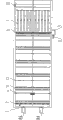
Fig. 3 is a kind of plan structure schematic diagram that is applied to the multistage spoil disposal sedimentation basin of folded plate type in the sewage disposal of the utility model;
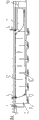
Fig. 4 is the main TV structure schematic diagram of sedimentation basin shown in Figure 3.
Among the figure:
1---gate 2---water distribution orifice plate 3---distributing hole
4---mud scraper 5---discharge pipeline 6---skimming pipes
7---water leg 8---effluent outfall 9---scum silica frost wells
10---delivery port 11---sludge bucket 12,12 '---flaps
The specific embodiment
As depicted in figs. 1 and 2, in the prior art, sewage enters rectangular sedimentation tank through gate 1, a plurality of distributing hole rectifications on water distribution orifice plate 2, and bottom horizontal flow sheet forward, sludge settling is at the bottom of the pond.Scrape pool bottom sludge by the outlet of pond body to porch (flow path direction against the current) in chain-plate type mud scraper 4 traveling process, scrape water surface scum silica frost to exit (Parallel to the flow direction) by pond body inlet.Mud is scraped to sludge bucket 11, drains through discharge pipeline 5, and scum silica frost enters scum silica frost well 9 through skimming pipe 6, and sewage is drained through effluent outfall 8 in the scum silica frost well 9.Water outlet overflow after the sedimentation enters water leg 7, enters down treatment process one through delivery port 10.
A kind of multistage spoil disposal sedimentation basin of folded plate type that is applied in the sewage disposal of the utility model is on the basis of above-mentioned traditional rectangular sedimentation tank, have additional length and the identical flap of pond body width at Chi Tizhong, the pond basal surface is designed to horizontal plane, and at the bottom of the pond from body porch, pond to the exit (along water (flow) direction) establish a plurality of sludge buckets.
Below in conjunction with the drawings and specific embodiments (with treating capacity is 50,000 t/d, uses the preliminary sedimentation tank of chain-plate type mud scraper to be example) the utility model is done to describe in further detail.
As shown in Figure 3 and Figure 4, a kind of structure that is applied to the multistage spoil disposal sedimentation basin of folded plate type in the sewage disposal of the utility model is, comprises the pond body, and described pond body is provided with inlet gate 1 and delivery port 10; Be provided with water distribution orifice plate 2, mud scraper 4, skimming pipe 6 and water leg 7 from described inlet gate 1 successively between the described delivery port 10 in the body of described pond; Described skimming pipe 6 is connected to a scum silica frost well 9, and described scum silica frost well 9 is provided with effluent outfall 8; Body bottom, described pond is provided with sludge bucket 11, and described pond basal surface is for being horizontally disposed with; Change traditional rectangular sedimentation tank only is provided with sludge bucket in the porch spoil disposal pattern, along water (flow) direction (from body porch, pond to the exit) a plurality of sludge buckets 11 are set at the bottom of the pond, the mud of precipitation can in time be drained, the size of sludge bucket 11 is according to the content of sewage by suspended thing, and moisture percentage in sewage sludge is determined with the concrete number that sludge bucket is set.Described sludge bucket 11 bottoms are provided with discharge pipeline 5, be provided with the identical flap of width of a plurality of its length and described pond body in the body of described pond, to prolong flow path, also good sedimentation effect can be arranged when suspension content is higher, described a plurality of flap is distributed near Chi Ding with near arranging on two height and positions at the bottom of the pond and along water (flow) direction, is staggered near the flap 12 of Chi Ding with near the flap 12 ' at the bottom of the pond.Number mainly is according to handling the water yield and scraping mud.Length specific to described flap mainly is according to handling the water yield and scrape mud equipment and determine, being advisable with normal operation and the assurance water velocity≤0.1m/s that does not influence mud scraper with vertical riding position.
At handling 50,000 t/d town sewages, adopt the flat flow coprecipitation mode, because the sludge bucket degree of depth reduces, the sedimentation basin degree of depth can reduce about 2m thereupon behind a kind of multistage spoil disposal sedimentation basin of folded plate type that is applied in the sewage disposal of application the utility model.Longitudinal gradient no longer is set at the bottom of the pond, has reduced the difficulty of construction and erection unit, the setting of flap improves treatment effect and capacity of resisting impact load greatly, and multistage spoil disposal pattern has been eliminated the mud rising phenomenon that water inlet end occurs.
Although in conjunction with figure the utility model is described above; but the utility model is not limited to the above-mentioned specific embodiment; the above-mentioned specific embodiment only is schematic; rather than it is restrictive; those of ordinary skill in the art is under enlightenment of the present utility model; under the situation that does not break away from the utility model aim, can also make a lot of distortion, these all belong within the protection of the present utility model.
Claims (3)
1. the multistage spoil disposal sedimentation basin of folded plate type that is applied in the sewage disposal comprises the pond body, and described pond body is provided with inlet gate (1) and delivery port (10); Be provided with water distribution orifice plate (2), mud scraper (4), skimming pipe (6) and water leg (7) from described inlet gate (1) successively between the described delivery port (10) in the body of described pond; Described skimming pipe (6) is connected to a scum silica frost well (9), and described scum silica frost well (9) is provided with effluent outfall (8); Body bottom, described pond is provided with sludge bucket (11), it is characterized in that,
Described pond basal surface is for being horizontally disposed with; Described sludge bucket (11) is a plurality of; Be provided with the identical flap of width of a plurality of its length and described pond body in the body of described pond; Described a plurality of flap is distributed near Chi Ding with near arranging on two height and positions at the bottom of the pond and along water (flow) direction, is staggered near the flap (12) of Chi Ding with near the flap (12 ') at the bottom of the pond.
2. according to the described a kind of multistage spoil disposal sedimentation basin of folded plate type that is applied in the sewage disposal of claim 1, it is characterized in that described a plurality of sludge buckets (11) are to arrange successively along water (flow) direction in the layout at the bottom of the pond.
3. according to the described a kind of multistage spoil disposal sedimentation basin of folded plate type that is applied in the sewage disposal of claim 1, it is characterized in that described sludge bucket (11) bottom is provided with discharge pipeline (5).
Priority Applications (1)
| Application Number | Priority Date | Filing Date | Title |
|---|---|---|---|
| CN201020582708XU CN201848131U (en) | 2010-10-29 | 2010-10-29 | Table-flap type multi-stage mud-discharge settling tank applied to sewage treatment |
Applications Claiming Priority (1)
| Application Number | Priority Date | Filing Date | Title |
|---|---|---|---|
| CN201020582708XU CN201848131U (en) | 2010-10-29 | 2010-10-29 | Table-flap type multi-stage mud-discharge settling tank applied to sewage treatment |
Publications (1)
| Publication Number | Publication Date |
|---|---|
| CN201848131U true CN201848131U (en) | 2011-06-01 |
Family
ID=44090546
Family Applications (1)
| Application Number | Title | Priority Date | Filing Date |
|---|---|---|---|
| CN201020582708XU Expired - Lifetime CN201848131U (en) | 2010-10-29 | 2010-10-29 | Table-flap type multi-stage mud-discharge settling tank applied to sewage treatment |
Country Status (1)
| Country | Link |
|---|---|
| CN (1) | CN201848131U (en) |
Cited By (12)
| Publication number | Priority date | Publication date | Assignee | Title |
|---|---|---|---|---|
| CN102861463A (en) * | 2011-07-05 | 2013-01-09 | 陈谷 | Mobile water-distribution/collection type sedimentation tank |
| CN103505916A (en) * | 2012-06-15 | 2014-01-15 | 月岛机械株式会社 | Sludge digging machine |
| CN104028011A (en) * | 2014-04-23 | 2014-09-10 | 浙江海河环境科技有限公司 | Horizontal-flow multi-bucket fractional precipitation device for chemical-free treatment of machine-made sand waste water |
| CN104922946A (en) * | 2015-06-26 | 2015-09-23 | 浙江特拉建材有限公司 | Wastewater pretreatment equipment |
| CN105170312A (en) * | 2015-08-14 | 2015-12-23 | 昆明理工大学 | Tailing classifying and ore drawing device |
| CN105363249A (en) * | 2015-11-17 | 2016-03-02 | 徐州工程学院 | Horizontal-flow sedimentation device and water purifying method thereof |
| CN105779275A (en) * | 2016-05-17 | 2016-07-20 | 农业部沼气科学研究所 | Biogas fermentation and biogas residue sedimentation integrated device |
| CN106731046A (en) * | 2016-12-30 | 2017-05-31 | 日照市光润模具制造有限公司 | Stone material cutting sewage fine deposition shakes out system |
| CN107418879A (en) * | 2017-08-30 | 2017-12-01 | 博能盛诺(北京)生物质能源科技有限公司 | Installation for fermenting and stalk marsh gas system |
| CN111821729A (en) * | 2020-07-31 | 2020-10-27 | 同济大学建筑设计研究院(集团)有限公司 | Horizontal-flow type settling pond scum cleaning device |
| CN113797607A (en) * | 2020-06-17 | 2021-12-17 | 沁欧环保科技(上海)有限公司 | Double-layer sedimentation tank |
| CN118791126A (en) * | 2024-07-31 | 2024-10-18 | 中电建生态环境集团有限公司 | Municipal sewage activated sludge treatment system combined with membrane separation device |
-
2010
- 2010-10-29 CN CN201020582708XU patent/CN201848131U/en not_active Expired - Lifetime
Cited By (16)
| Publication number | Priority date | Publication date | Assignee | Title |
|---|---|---|---|---|
| CN102861463B (en) * | 2011-07-05 | 2015-12-16 | 上海同臣环保有限公司 | A kind of mobile cloth, water-collecting type sedimentation basin |
| CN102861463A (en) * | 2011-07-05 | 2013-01-09 | 陈谷 | Mobile water-distribution/collection type sedimentation tank |
| CN103505916A (en) * | 2012-06-15 | 2014-01-15 | 月岛机械株式会社 | Sludge digging machine |
| CN103505916B (en) * | 2012-06-15 | 2016-05-11 | 月岛机械株式会社 | Mud dredger |
| CN104028011A (en) * | 2014-04-23 | 2014-09-10 | 浙江海河环境科技有限公司 | Horizontal-flow multi-bucket fractional precipitation device for chemical-free treatment of machine-made sand waste water |
| CN104922946A (en) * | 2015-06-26 | 2015-09-23 | 浙江特拉建材有限公司 | Wastewater pretreatment equipment |
| CN105170312A (en) * | 2015-08-14 | 2015-12-23 | 昆明理工大学 | Tailing classifying and ore drawing device |
| CN105363249B (en) * | 2015-11-17 | 2017-05-10 | 徐州工程学院 | A kind of horizontal sedimentation device and its water purification method |
| CN105363249A (en) * | 2015-11-17 | 2016-03-02 | 徐州工程学院 | Horizontal-flow sedimentation device and water purifying method thereof |
| CN105779275A (en) * | 2016-05-17 | 2016-07-20 | 农业部沼气科学研究所 | Biogas fermentation and biogas residue sedimentation integrated device |
| CN106731046A (en) * | 2016-12-30 | 2017-05-31 | 日照市光润模具制造有限公司 | Stone material cutting sewage fine deposition shakes out system |
| CN107418879A (en) * | 2017-08-30 | 2017-12-01 | 博能盛诺(北京)生物质能源科技有限公司 | Installation for fermenting and stalk marsh gas system |
| CN107418879B (en) * | 2017-08-30 | 2023-11-03 | 博能盛诺(北京)生物质能源科技有限公司 | Fermentation device and straw biogas system |
| CN113797607A (en) * | 2020-06-17 | 2021-12-17 | 沁欧环保科技(上海)有限公司 | Double-layer sedimentation tank |
| CN111821729A (en) * | 2020-07-31 | 2020-10-27 | 同济大学建筑设计研究院(集团)有限公司 | Horizontal-flow type settling pond scum cleaning device |
| CN118791126A (en) * | 2024-07-31 | 2024-10-18 | 中电建生态环境集团有限公司 | Municipal sewage activated sludge treatment system combined with membrane separation device |
Similar Documents
| Publication | Publication Date | Title |
|---|---|---|
| CN201848131U (en) | Table-flap type multi-stage mud-discharge settling tank applied to sewage treatment | |
| CN101879383B (en) | Turn-back flow high-efficiency rectangular double-layer settling pond | |
| CN104174191B (en) | Integrated grit chamber for treating rainwater and treatment method | |
| CN108996740A (en) | A kind of just rain processing system and method | |
| CN203447839U (en) | High-efficiency sedimentation basin | |
| CN219489718U (en) | A separate gravel filter bed structure with dam water diversion | |
| CN210710975U (en) | Sloping plate-air flotation mud-water separation tank | |
| CN110478978B (en) | A circular self-discharging gravity sand filter | |
| CN105363249B (en) | A kind of horizontal sedimentation device and its water purification method | |
| CN203989972U (en) | Integrated grit chamber for treating rainwater | |
| CN2748467Y (en) | Water-quenching slag-washing water treatment device for blast furnace slag | |
| CN211863978U (en) | Efficient sludge discharge sedimentation tank | |
| CN203060904U (en) | Improved advection setting device | |
| CN205340235U (en) | Sedimentation tank device of wall is depositd in area | |
| CN203281084U (en) | Anti-blocking precipitator | |
| CN202185189U (en) | Iron ore concentrate slurry sewage treatment sedimentation tank | |
| CN208577484U (en) | Chemical-free secondary hydraulically enhanced coagulation sedimentation tank | |
| CN207483452U (en) | A kind of nonclogging artificial wet land system | |
| CN202170286U (en) | Sludge reduction and concentration basin | |
| CN202087090U (en) | Sedimentation device | |
| CN110743212A (en) | A high-efficiency sludge sedimentation tank | |
| CN204261393U (en) | Vertically disposed inclined-plate clarifying basin | |
| CN204637669U (en) | Flat flow primary sedimentation pond | |
| CN211912833U (en) | Water outlet equipment for removing floating mud in upflow water treatment structure | |
| CN105256875A (en) | Levee-type initial stage rainwater interception-storage-processing combined system |
Legal Events
| Date | Code | Title | Description |
|---|---|---|---|
| C14 | Grant of patent or utility model | ||
| GR01 | Patent grant | ||
| CX01 | Expiry of patent term | ||
| CX01 | Expiry of patent term |
Granted publication date: 20110601 |