CN201848118U - Pressure-bearing leaching tank - Google Patents
Pressure-bearing leaching tank Download PDFInfo
- Publication number
- CN201848118U CN201848118U CN2010205526330U CN201020552633U CN201848118U CN 201848118 U CN201848118 U CN 201848118U CN 2010205526330 U CN2010205526330 U CN 2010205526330U CN 201020552633 U CN201020552633 U CN 201020552633U CN 201848118 U CN201848118 U CN 201848118U
- Authority
- CN
- China
- Prior art keywords
- tank body
- tank
- pressure
- material cage
- air inlet
- Prior art date
- Legal status (The legal status is an assumption and is not a legal conclusion. Google has not performed a legal analysis and makes no representation as to the accuracy of the status listed.)
- Expired - Fee Related
Links
- 238000002386 leaching Methods 0.000 title claims abstract description 15
- 239000000463 material Substances 0.000 claims abstract description 48
- 239000002904 solvent Substances 0.000 claims abstract description 16
- 238000005192 partition Methods 0.000 claims abstract description 11
- 239000007788 liquid Substances 0.000 claims abstract description 9
- 239000000126 substance Substances 0.000 abstract description 2
- 238000000034 method Methods 0.000 description 6
- 239000007789 gas Substances 0.000 description 3
- LCGLNKUTAGEVQW-UHFFFAOYSA-N Dimethyl ether Chemical compound COC LCGLNKUTAGEVQW-UHFFFAOYSA-N 0.000 description 2
- ATUOYWHBWRKTHZ-UHFFFAOYSA-N Propane Chemical compound CCC ATUOYWHBWRKTHZ-UHFFFAOYSA-N 0.000 description 2
- 238000005516 engineering process Methods 0.000 description 2
- 238000000605 extraction Methods 0.000 description 2
- 210000001503 joint Anatomy 0.000 description 2
- 238000004519 manufacturing process Methods 0.000 description 2
- 238000001556 precipitation Methods 0.000 description 2
- LVGUZGTVOIAKKC-UHFFFAOYSA-N 1,1,1,2-tetrafluoroethane Chemical compound FCC(F)(F)F LVGUZGTVOIAKKC-UHFFFAOYSA-N 0.000 description 1
- FGRBYDKOBBBPOI-UHFFFAOYSA-N 10,10-dioxo-2-[4-(N-phenylanilino)phenyl]thioxanthen-9-one Chemical compound O=C1c2ccccc2S(=O)(=O)c2ccc(cc12)-c1ccc(cc1)N(c1ccccc1)c1ccccc1 FGRBYDKOBBBPOI-UHFFFAOYSA-N 0.000 description 1
- 229910018503 SF6 Inorganic materials 0.000 description 1
- 230000009286 beneficial effect Effects 0.000 description 1
- 239000001273 butane Substances 0.000 description 1
- 239000012530 fluid Substances 0.000 description 1
- 238000013467 fragmentation Methods 0.000 description 1
- 238000006062 fragmentation reaction Methods 0.000 description 1
- 238000002309 gasification Methods 0.000 description 1
- 239000008187 granular material Substances 0.000 description 1
- 230000008676 import Effects 0.000 description 1
- 239000003915 liquefied petroleum gas Substances 0.000 description 1
- IJDNQMDRQITEOD-UHFFFAOYSA-N n-butane Chemical compound CCCC IJDNQMDRQITEOD-UHFFFAOYSA-N 0.000 description 1
- OFBQJSOFQDEBGM-UHFFFAOYSA-N n-pentane Natural products CCCCC OFBQJSOFQDEBGM-UHFFFAOYSA-N 0.000 description 1
- 239000000843 powder Substances 0.000 description 1
- 239000001294 propane Substances 0.000 description 1
- 239000011343 solid material Substances 0.000 description 1
- 230000003068 static effect Effects 0.000 description 1
- SFZCNBIFKDRMGX-UHFFFAOYSA-N sulfur hexafluoride Chemical compound FS(F)(F)(F)(F)F SFZCNBIFKDRMGX-UHFFFAOYSA-N 0.000 description 1
- 229960000909 sulfur hexafluoride Drugs 0.000 description 1
Images

Classifications
-
- Y—GENERAL TAGGING OF NEW TECHNOLOGICAL DEVELOPMENTS; GENERAL TAGGING OF CROSS-SECTIONAL TECHNOLOGIES SPANNING OVER SEVERAL SECTIONS OF THE IPC; TECHNICAL SUBJECTS COVERED BY FORMER USPC CROSS-REFERENCE ART COLLECTIONS [XRACs] AND DIGESTS
- Y02—TECHNOLOGIES OR APPLICATIONS FOR MITIGATION OR ADAPTATION AGAINST CLIMATE CHANGE
- Y02P—CLIMATE CHANGE MITIGATION TECHNOLOGIES IN THE PRODUCTION OR PROCESSING OF GOODS
- Y02P10/00—Technologies related to metal processing
- Y02P10/20—Recycling
Landscapes
- Extraction Or Liquid Replacement (AREA)
Abstract
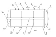
The utility model relates to a pressure-loading leaching tank, belonging to the chemical industrial plant component extracting equipment. The technical scheme of the utility model is that the left end seal end of a cylindrical tank of a horizontal pressure-bearing leaching tank is integrated with a tank body, a hot air inlet is arranged at the axis of the horizontal pressure-bearing leaching tank, the hot air inlet is communicated with an air inlet pipe in the tank body, a quick-opening seal end is arranged at the right end of the tank body, a seal piece is arranged between the quick-opening seal end and the tank body, a cylindrical material cage is arranged in the tank body, an air inlet pipe penetrates through the axis position of the cylindrical material cage, a partition board is respectively arranged at the left end and the right end of the material cage, a bin partition board is arranged in the material cage, the material cage is placed on a semicircular plate trailer, two groups of guide wheels are arranged at the bottom part of the plate trailer, the guide wheels are placed in a guide rail, and the guide rail is fixed on the inner wall of the tank body; a solvent inlet, an air outlet pipe, a safety valve, a pressure meter, a thermometer and an air outlet are arranged at the upper part of the tank body, and a liquid outlet is arranged at the lower part of the tank body; the materials of the wall of the material cage, the partition boards, the bin partition board and the wall of the air inlet pipe are filter screens or plate grids or sieve plates, the number of the joints of the material cages is 1-10, the adjacent joints are respectively butted by a birdmouth, and the number of partition bins in the material cage is 2-20.
Description
Technical field
The utility model belongs to chemical industry plant component extraction equipment.
Background technology
The pressure-bearing batch extractor structure of using is at present: horizontal or vertical pressure vessel, top are provided with charging aperture and two charging valves are installed, and the bottom is provided with discharge gate and double material valve is installed.For the leaching liquid in the drain tank, the bottom is provided with the fluid mouth of pipe of band filter plate.For solid material being discharged smoothly and being unlikely the material caking, be provided with paddle in jar, the power outer by jar drives.Tank body is a pressure vessel, can bear the pressure of jar internal solvent.To be liquefied propane, liquefied butane, liquefied petroleum gas, HFC-134a, sulfur hexafluoride, dimethyl ether etc. be the solvent of liquid under normal temperature and certain pressure with the leaching solvent.
The shortcoming of the pressure-bearing batch extractor that uses is at present: complex structure, and because of input and output material valve rapid wear poor stability, dangerous because of there being shaft to stretch out easy leakage solvent on the tank body.Especially the material that leaches can be blended and influence the quality of product.Be subjected to the restriction of liquid outlet filter-plate structure, can not leach pulverous material.
Summary of the invention
The purpose of this utility model is in order to overcome the shortcoming of existing equipment, to change production equipment and technology and significantly improve production efficiency.
The technical solution of the utility model is: the cylindric tank body left end end socket and the tank body of horizontal pressure-bearing batch extractor are structure as a whole, its shaft core position is provided with the hot blast import, be communicated with blast pipe in the tank body, the tank body right-hand member is provided with fast Kaifeng head, between fast Kaifeng head and the tank body seal is arranged, tank interior has cylindric material cage, its shaft core position is through with blast pipe, and there is dividing plate at material two ends, the cage left and right sides, and there is partition panel inside, the material cage is placed on the semicircle wooden handcart, the wooden handcart bottom is provided with two groups of guide wheels, and guide wheel places guide rail, and guide rail is fixed on the inner tank wall, solvent inlet is arranged at tank body top, escape pipe, safety valve, Pressure gauge, thermometer and air outlet, liquid outlet is arranged at the tank body bottom; The material of material cage wall, dividing plate, partition panel, air intake tube wall is filter screen or screen or sieve plate, and the material cage is 1-10 joints, by the birdsmouth butt joint, divides compartment to be 2-20 in the material cage between every joint.
The beneficial effects of the utility model: simple in structure, because drive axle-free makes equipment safety and the difficult leakage of solvent more, can leach powder material, also can make inconvenient broken material keep finishing leaching process on its profile basis of invariable.
Description of drawings
Accompanying drawing 1 is the utility model structural representation.
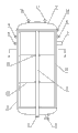
Accompanying drawing 2 is the utility model A-A generalized sections.
Accompanying drawing 3 is vertical batch extractor structural representations.
Accompanying drawing 4 is vertical batch extractor A-A generalized sections.
The specific embodiment
The utility model is a horizontal or vertical cylindric pressure vessel, and the one end is ripe fast Kaifeng header structure, and the other end is a container end socket commonly used.Before horizontal pressure-bearing batch extractor is started working, earlier material is contained in the material cage 10, material cage 10 is placed on the semicircle wooden handcart 20, wooden handcart has guide wheel 12 20 times, guide wheel 12 is gone in the jar from fast Kaifeng 9 one thruster of opening along guide rail 11, after shutting fast Kaifeng 9, add from solvent inlet 4 and to leach solvents, material can be leached by solvent statically.After leachate drains from bottom liquid outlet 8, opening gas outlet 5 valves makes the solvent gasification discharge in the material carry out precipitation, when the jar internal pressure is reduced to normal pressure, introduce the solvent hot blast from air inlet 1, hot blast sees through material, solvent remaining in the material is further evaporated, the 5 solvent gas extractions that vacuumize space in the jar from the gas outlet at last, after above-mentioned leaching and precipitation process are finished, opening air inlet 1 makes and becomes normal pressure in the tank body, open fast Kaifeng 9 again, sweep and material are pulled out, promptly finish leaching process one time.Material cage 10, dividing plate 13, partition panel 14, blast pipe 2 walls can be selected filter screen, screen or sieve plate, and for granular material, solvent can enter and material can not spill.Be static in the material leaching process, so overall process can not cause the fragmentation of outward appearance to material.In the middle of the material cage 10 blast pipe 2 is arranged, blast pipe 2 is docked mutually by birdsmouth 15.Establish a wooden handcart 20 in the horizontal pressure-bearing batch extractor, can place 1-10 material cages 10 on the wooden handcart.Material cage 10 is fixed on the wooden handcart 20.Be provided with 2-20 compartments 19 in each material cage 10, make top the cavity occur in case material slides into the bottom, cause the wind short circuit.Liquid outlet 8 is 1-2.
The difference of vertical bearing batch extractor and horizontal pressure-bearing batch extractor is that its top is provided with Pressure gauge 16, thermometer 17, feed tube 4, escape pipe 5, air outlet 7, the safety valve mouth of pipe 6 are arranged at top, tank body side, drain pipe 8 is arranged at the bottom, air intake pipe orifice 1 is arranged on the low head, guide wheel 12 and guide rail 11 between the wooden handcart 20 of vertical bearing batch extractor and the material cage 10 evenly distribute along tank body 3 inwall circumference, quantity is no less than 3 groups, is used for material cage 10 fixed position when tank deck hangs is used.Its operation principle and flow process are identical with horizontal batch extractor, repeat no more herein.
Claims (4)
Priority Applications (1)
| Application Number | Priority Date | Filing Date | Title |
|---|---|---|---|
| CN2010205526330U CN201848118U (en) | 2010-07-29 | 2010-10-08 | Pressure-bearing leaching tank |
Applications Claiming Priority (3)
| Application Number | Priority Date | Filing Date | Title |
|---|---|---|---|
| CN201010239134.0 | 2010-07-29 | ||
| CN201010239134 | 2010-07-29 | ||
| CN2010205526330U CN201848118U (en) | 2010-07-29 | 2010-10-08 | Pressure-bearing leaching tank |
Publications (1)
| Publication Number | Publication Date |
|---|---|
| CN201848118U true CN201848118U (en) | 2011-06-01 |
Family
ID=44090533
Family Applications (1)
| Application Number | Title | Priority Date | Filing Date |
|---|---|---|---|
| CN2010205526330U Expired - Fee Related CN201848118U (en) | 2010-07-29 | 2010-10-08 | Pressure-bearing leaching tank |
Country Status (1)
| Country | Link |
|---|---|
| CN (1) | CN201848118U (en) |
Cited By (1)
| Publication number | Priority date | Publication date | Assignee | Title |
|---|---|---|---|---|
| CN103213778A (en) * | 2013-04-26 | 2013-07-24 | 张家港韩中深冷科技有限公司 | Strain strengthening storage tank |
-
2010
- 2010-10-08 CN CN2010205526330U patent/CN201848118U/en not_active Expired - Fee Related
Cited By (1)
| Publication number | Priority date | Publication date | Assignee | Title |
|---|---|---|---|---|
| CN103213778A (en) * | 2013-04-26 | 2013-07-24 | 张家港韩中深冷科技有限公司 | Strain strengthening storage tank |
Similar Documents
| Publication | Publication Date | Title |
|---|---|---|
| CN205235464U (en) | Multi -functional subcritical extraction equipment | |
| CN201848118U (en) | Pressure-bearing leaching tank | |
| CN202724746U (en) | Liquid-liquid extraction tower with multistage counterflow variable diameters | |
| CN204709854U (en) | A kind of integrated crystallization apparatus with centrifugal drying function | |
| CN203363678U (en) | Pollution discharge and treatment device of coal gas drainage system | |
| CN205182721U (en) | Reaction kettle | |
| CN204973151U (en) | Ammoniation reaction's gas -liquid separation tower | |
| CN203379664U (en) | Scraping plate type precision filter device for paint | |
| CN203620377U (en) | Liquid filtering device | |
| CN204564112U (en) | acid treatment device | |
| CN203315826U (en) | Liquid conveying device for solid-liquid separation and filter tank thereof | |
| CN203753681U (en) | Liquid-state chemical product storage tank | |
| CN204073546U (en) | Filter press separately-loaded corollary equipment assembly | |
| CN205896520U (en) | Pipeline for water conservancy project | |
| CN204973442U (en) | Many phase separator | |
| CN207769746U (en) | Retort adjustable sealing Dump gate | |
| CN205146164U (en) | CO2 drying reaction kettle multi -channel structure that connects in parallel | |
| CN202968149U (en) | Equipment for jointing coating process and washing process of titanium dioxide production | |
| CN206184326U (en) | Large capacity repacking type serial -type mediation cauldron | |
| CN204933289U (en) | Multi-filtering rate formula Alkaline etchant liquid dispensing device | |
| CN205781989U (en) | A kind of spherical tank blow-off line | |
| CN105062124B (en) | A system for rapid extraction of pigment from azalea | |
| CN203975653U (en) | A kind of tar tank gas phase blow-down pipe for Recycling of waste liquid | |
| CN204939616U (en) | Multi-filtering rate formula acid etching mother liquor liquid dispensing device | |
| CN203990027U (en) | Coal gas liquid y-type filter filter element device |
Legal Events
| Date | Code | Title | Description |
|---|---|---|---|
| C14 | Grant of patent or utility model | ||
| GR01 | Patent grant | ||
| CF01 | Termination of patent right due to non-payment of annual fee |
Granted publication date: 20110601 Termination date: 20181008 |
|
| CF01 | Termination of patent right due to non-payment of annual fee |