CN201825652U - Cart running and steering mechanism of beam hoisting machine - Google Patents
Cart running and steering mechanism of beam hoisting machine Download PDFInfo
- Publication number
- CN201825652U CN201825652U CN2010205725777U CN201020572577U CN201825652U CN 201825652 U CN201825652 U CN 201825652U CN 2010205725777 U CN2010205725777 U CN 2010205725777U CN 201020572577 U CN201020572577 U CN 201020572577U CN 201825652 U CN201825652 U CN 201825652U
- Authority
- CN
- China
- Prior art keywords
- flange
- bogie frame
- horizontal shaft
- vertical post
- steering mechanism
- Prior art date
- Legal status (The legal status is an assumption and is not a legal conclusion. Google has not performed a legal analysis and makes no representation as to the accuracy of the status listed.)
- Expired - Fee Related
Links
Images

Landscapes
- Carriers, Traveling Bodies, And Overhead Traveling Cranes (AREA)
Abstract
The utility model discloses a cart running and steering mechanism of a beam hoisting machine, comprising a lower cross beam, a flange and a table frame, wherein the table frame is connected with the flange through a pin shaft, and the flange is connected with the lower cross beam through a bolt. The cart running and steering mechanism also comprises a vertical post and a horizontal shaft, wherein the bottom of the vertical post is welded on the flange, and the upper end of the vertical post is inserted into the lower cross beam; and the horizontal shaft is arranged at the upper part of the vertical post, and both ends of the horizontal shaft are provided with rotatable shaft sleeves. In the utility model, the flange and the table frame rise to an escape track along with the lower cross beam through the supporting action of the horizontal shaft in the supporting and rotating device, and the horizontal shaft is driven to rotate around the center of the vertical post through the movable shaft sleeves, so that the vertical and horizontal steering of the table frame is realized. The cart running and steering mechanism has the advantages of low cost, convenience in steering, wide operation area, high working efficiency, and simple structure and is mainly suitable for track type general portal cranes.
Description
Technical field
The utility model relates to a kind of Liang Chang lifting and uses the gate-type weight-lifting equipment, relates in particular to a kind of lifting beam machine cart operation steering hardware.
Background technology
The general gate-type bale handle of existing rail mounted hoisting crane, lifting in its beam making field, when moving beam, car loading operation, no matter under zero load or loading condition, generally speaking all can only traveling on a trapped orbit, and can not commutate.But the track of high speed railway beam making field is that vertical interlaced is arranged in length and breadth, thereby must use several lifting beam machines to be distributed in operation on each long rails and the cross track, so cause each lifting beam machine but can't make adjustment in the busy not busy inequality to operation in length and breadth.It is busy to tend to occur the lifting beam machine operation on the direction, and the lifting beam machine on the other direction stagnate need not, not only can influence the work efficiency of whole beam making field, also correspondingly reduced the degree of utilization of lifting beam machine.
In order to address the above problem, application number is that 200620130126.1 Chinese patent discloses a kind of method of setting up jacking apparatus and walking wheels below the bale handle hoisting crane, is provided with drive motor and steering hardware on its walking wheels.In use, jacking apparatus lifts the bale handle hoisting crane makes it built on stilts, and drive motor drives steering hardware again turns to the walking wheels, thereby realizes the commutation of bale handle hoisting crane.But commutation method has not only strengthened use cost like this, also makes more heavy that the bale handle hoisting crane becomes, and the operating power of whole hoisting crane not only increases, and the deadweight of structure itself also increases, and causes the wheel wheel load to increase, and disposes raising, is not suitable for widespread use.
The utility model content
The purpose of this utility model is to provide a kind of lifting beam machine cart simple in structure, that cost is low, safe to move steering hardware.
This lifting beam machine cart operation steering hardware that the utility model provides, comprise cross sill, flange and bogie frame, described bogie frame is connected with flange by bearing pin, described flange is connected with cross sill by bolt, also comprise and be used for slinging and driving the support slewing arrangement that bogie frame rotates, described support slewing arrangement comprises column and the horizontal shaft of vertically laying, the bottom of described column is welded on the flange, insert in the cross sill its upper end, described horizontal shaft is installed in the top of column, and its two ends are provided with rotatable axle sleeve.
Described bogie frame comprises left bogie frame and right bogie frame, and a rail sweep and a Warning light are housed on described left bogie frame, and a rail clamping device and an energy disperser are housed on described right bogie frame.
The utility model by supporting the supporting role of horizontal shaft in the slewing arrangement, made flange and bogie frame de-orbit along with cross sill rises to before this, drove horizontal shaft around the rotation of column center by movable axle sleeve again, thus realize bogie frame commutation in length and breadth.The utility model cost is low, turns to conveniently, and working area is wide, and high efficiency is simple in structure, mainly is applicable to the rail mounted gantry crane for general use.
Description of drawings
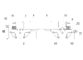
Fig. 1 is the utility model transversary scheme drawing.
Fig. 2 is the utility model longitudinal construction scheme drawing.
Fig. 3 is the structural representation that Fig. 1 supports rotational structure.
The specific embodiment
From Fig. 1 to Fig. 3 as can be seen, this lifting beam machine cart operation steering hardware of the present utility model, comprise cross sill 1, flange 2, bogie frame and support rotational structure 5, wherein bogie frame comprises left bogie frame 3 and right bogie frame 4, adhesion wheel group and passive set of wheels all are installed in left bogie frame 3 and right bogie frame 4, a rail sweep 31 and a Warning light 32 are housed on left bogie frame 3, a rail clamping device 41 and an energy disperser 42 are housed on right bogie frame 4, each bogie frame is connected with flange 2 by bearing pin, each flange 2 is connected and is distributed in the two ends of cross sill 1 by bolt and cross sill 1, support rotational structure 5 and comprise vertically arranged column 51 and horizontal shaft 52, the bottom of column 51 is welded on the flange 2, respectively have a through hole in the bottom at cross sill 1 two ends, the upper end of column 51 is inserted in the cross sill also rotatable by this through hole, horizontal shaft 52 is installed in the top of column 51, and its two ends all are with rotatable axle sleeve 53.
When the utility model uses, may further comprise the steps:
One, Liang Chang needs to arrange track before turning to first, transverse rails is apart from equaling the hoisting crane span, vertically gauge should equal the cart cardinal distance, need be furnished with the track of a demountable 1m of being about in length and breadth to the rail joint place, and its two ends can be docked with cross track and long rails respectively.
Two, hoisting crane is opened in length and breadth to the rail joint place, and range estimation guarantees the centrally aligned orbit centre of each left and right bogie frame two wheel center distance, to guarantee turning to rear wheel to drop on the track smoothly.
Three, between the track of cross sill 1 and parallel beneath, put the hydraulic lifting oil cylinder, and the track place below the hydraulic lifting oil cylinder spreads sleeper, guarantee that crosstie surface is concordant with track upper surface, on sleeper, spread the thick steel plate of 10mm then, guarantee that steel plate contacts fully with sleeper, track; Dismantle each flange 2 and cross sill 1 bonded assembly bolt.
Four, starting hydraulic power unit primer fluid compressing cylinder jacking to hoisting crane rises.
Five, when hoisting crane rises to certain position, cross sill 1 inner bottom surface contact with axle sleeve 53 on the horizontal shaft 52 that supports rotational structure 5, supports and drive flange and left and right bogie frame rise to together and de-orbit.
Six, change after the staff pulls down the former detachable track that contacts with cross track that contact good back with long rails fixing into.
Seven, the staff uses instruments such as crowbar, and major and minor bogie frame is carried out in the same way (all cw or all inverse clock) half-twist.
Eight, the top lift of unloading hydraulic ram allows major and minor bogie frame wheel all drop on the long rails.
Nine, fixing major and minor bogie frame and cross sill 1 bonded assembly bolt.
Ten, cart turns to and finishes.
Claims (2)
1. a lifting beam machine cart moves steering hardware, comprise cross sill (1), flange (2) and bogie frame, described bogie frame is connected with flange (2) by bearing pin, described flange (2) is connected with cross sill (1) by bolt, it is characterized in that also comprising and be used for slinging and driving the support slewing arrangement (5) that bogie frame rotates, described support slewing arrangement (5) comprises column (51) and the horizontal shaft of vertically laying (52), the bottom of described column (51) is welded on the flange (2), insert in the cross sill (1) its upper end, described horizontal shaft (52) is installed in the top of column (51), and its two ends are provided with rotatable axle sleeve (53).
2. lifting beam machine cart operation steering hardware according to claim 1, it is characterized in that described bogie frame comprises left bogie frame (3) and right bogie frame (4), a rail sweep (31) and a Warning light (32) are housed on described left bogie frame (3), a rail clamping device (41) and an energy disperser (42) are housed on described right bogie frame (4).
Priority Applications (1)
| Application Number | Priority Date | Filing Date | Title |
|---|---|---|---|
| CN2010205725777U CN201825652U (en) | 2010-10-22 | 2010-10-22 | Cart running and steering mechanism of beam hoisting machine |
Applications Claiming Priority (1)
| Application Number | Priority Date | Filing Date | Title |
|---|---|---|---|
| CN2010205725777U CN201825652U (en) | 2010-10-22 | 2010-10-22 | Cart running and steering mechanism of beam hoisting machine |
Publications (1)
| Publication Number | Publication Date |
|---|---|
| CN201825652U true CN201825652U (en) | 2011-05-11 |
Family
ID=43964202
Family Applications (1)
| Application Number | Title | Priority Date | Filing Date |
|---|---|---|---|
| CN2010205725777U Expired - Fee Related CN201825652U (en) | 2010-10-22 | 2010-10-22 | Cart running and steering mechanism of beam hoisting machine |
Country Status (1)
| Country | Link |
|---|---|
| CN (1) | CN201825652U (en) |
Cited By (5)
| Publication number | Priority date | Publication date | Assignee | Title |
|---|---|---|---|---|
| CN104229626A (en) * | 2013-06-17 | 2014-12-24 | 上海久能机电制造有限公司 | Driving mechanism for steering of crane |
| CN106809725A (en) * | 2017-03-25 | 2017-06-09 | 无锡市翱宇特新科技发展有限公司 | The bottom trolley structure that a kind of large-sized gantry hangs |
| CN107601273A (en) * | 2016-06-16 | 2018-01-19 | 钟水龙 | A kind of crane turning platform underbody seat |
| CN108775247A (en) * | 2018-06-05 | 2018-11-09 | 辽宁三三工业有限公司 | A kind of anti-slip release mechanism of section of jurisdiction turning platform and its application method |
| CN110804950A (en) * | 2019-11-06 | 2020-02-18 | 郑州市市政工程总公司 | Safe and energy-saving beam transporting method for building bridge on bridge |
-
2010
- 2010-10-22 CN CN2010205725777U patent/CN201825652U/en not_active Expired - Fee Related
Cited By (7)
| Publication number | Priority date | Publication date | Assignee | Title |
|---|---|---|---|---|
| CN104229626A (en) * | 2013-06-17 | 2014-12-24 | 上海久能机电制造有限公司 | Driving mechanism for steering of crane |
| CN107601273A (en) * | 2016-06-16 | 2018-01-19 | 钟水龙 | A kind of crane turning platform underbody seat |
| CN107601273B (en) * | 2016-06-16 | 2018-12-28 | 江山锐意科技服务有限公司 | A kind of crane turning platform underbody seat |
| CN106809725A (en) * | 2017-03-25 | 2017-06-09 | 无锡市翱宇特新科技发展有限公司 | The bottom trolley structure that a kind of large-sized gantry hangs |
| CN108775247A (en) * | 2018-06-05 | 2018-11-09 | 辽宁三三工业有限公司 | A kind of anti-slip release mechanism of section of jurisdiction turning platform and its application method |
| CN110804950A (en) * | 2019-11-06 | 2020-02-18 | 郑州市市政工程总公司 | Safe and energy-saving beam transporting method for building bridge on bridge |
| CN110804950B (en) * | 2019-11-06 | 2022-01-25 | 郑州市市政工程总公司 | Safe and energy-saving beam transporting method for building bridge on bridge |
Similar Documents
| Publication | Publication Date | Title |
|---|---|---|
| CN102134043B (en) | Crawler hydraulic support assembling machine | |
| CN106968179B (en) | A kind of constructing device that Cast-in-situ Beam is carried out using self-propelled entirety falsework method | |
| CN201825652U (en) | Cart running and steering mechanism of beam hoisting machine | |
| CN212828416U (en) | Track bridge type bogie replacing device | |
| CN108213901A (en) | For the lifting tipper of engine room foundation assembling process | |
| CN217297045U (en) | High-adaptability mobile cantilever crane | |
| CN201635097U (en) | Mobile ballasting platform counterforce device | |
| CN210366808U (en) | Lifting and dismantling device for rail walking | |
| CN108166392A (en) | A kind of floorings hanging device and method | |
| CN111764613A (en) | High-altitude equipment installation device in rail traveling area of rail transit engineering and construction method | |
| CN208067693U (en) | Lifting tipper for engine room foundation assembling process | |
| CN213416065U (en) | Transportation lifting device of train maintenance platform | |
| CN215516409U (en) | Platform device for hoisting steel pipe column for subway | |
| CN201980887U (en) | Crawler-type hydraulic-bracket crane trolley | |
| CN202670975U (en) | Loading platform of mining elevator | |
| CN105731268A (en) | Cargo transportation, hoisting and transferring device | |
| CN213326604U (en) | High-altitude equipment installation device in rail traffic engineering rail traveling area | |
| CN212450522U (en) | Movable elevator with bearing platform | |
| CN104555750B (en) | A kind of transporting and hoisting machinery | |
| CN103545755A (en) | Track reversing device of cable drum carriage | |
| CN202829498U (en) | Hydraulic jacking device | |
| CN221544035U (en) | Portable supplementary dress roof beam device is used to portal crane | |
| CN111364300A (en) | Multifunctional construction vehicle for subway rail | |
| CN111547464A (en) | Roof mechanical transportation system | |
| CN111734432B (en) | Multifunctional combined crawler type lifting operation vehicle |
Legal Events
| Date | Code | Title | Description |
|---|---|---|---|
| C14 | Grant of patent or utility model | ||
| GR01 | Patent grant | ||
| CF01 | Termination of patent right due to non-payment of annual fee |
Granted publication date: 20110511 Termination date: 20151022 |
|
| EXPY | Termination of patent right or utility model |