CN201824125U - Bolt tightening machine - Google Patents
Bolt tightening machine Download PDFInfo
- Publication number
- CN201824125U CN201824125U CN2010205862276U CN201020586227U CN201824125U CN 201824125 U CN201824125 U CN 201824125U CN 2010205862276 U CN2010205862276 U CN 2010205862276U CN 201020586227 U CN201020586227 U CN 201020586227U CN 201824125 U CN201824125 U CN 201824125U
- Authority
- CN
- China
- Prior art keywords
- lathe bed
- bolt
- tightening
- screwing machine
- bolt screwing
- Prior art date
- Legal status (The legal status is an assumption and is not a legal conclusion. Google has not performed a legal analysis and makes no representation as to the accuracy of the status listed.)
- Expired - Fee Related
Links
Images


Landscapes
- Machine Tool Units (AREA)
Abstract
The utility model discloses a bolt tightening comprising a tightening shaft (1); the bolt tightening machine further comprises a bed which supports a circumferential rotation driving device (2); the circumferential rotation driving device (2) is connected with a tightening shaft frame (3) which rotates along with the circumferential rotation driving device (2); the tightening shaft (1) is arranged on the tightening shaft frame (3); the bolt tightening machine further comprises a control device which is connected with the circumferential rotation driving device (2) and the tightening shaft (1), so that the control device controls the tightening shaft (1) in a working plane for bolt tightening to move to a position where bolts need to be tightened, and then the tightening operation of the bolt is finished. The bolt tightening machine can improve both the efficiency and quality of bolt tightening.
Description
Technical field
The utility model relates to bolt and tightens technical field, particularly a kind of bolt screwing machine.
Background technology
The bolt connection is a kind of widely used detachably fixedly connected, has advantages such as simple in structure, that connection is reliable, mounting or dismounting are convenient, and in various large-scale, heavy electromechanical equipments, the bolt connection has obtained application widely.
In horizontal shaft type wind-driven generator, its requisite parts are the pitching slewing supports that are used to connect blade and wheel hub, and pitching slewing support be bolt being connected of blade and wheel hub and connect, and the quantity of the bolt that is used to connect is very many, thereby need tighten several times according to the specific order of tightening.In addition because pitching slewing support exists that load is big, load is complicated, thereby bolted quality is also required very high, require the screw-down torque of whole bolts all to be controlled to twist eventually moment ± 5% in.
The industry common practice is to adopt the method for artificial hand-held hydraulic spanner to tight a bolt at present, bolt is numbered and indicates by the method for drawing mark successively the tight condition of bolt with marking pen.There is following shortcoming in this method:
The first, adopt the mode efficient of manually tightening low, and owing to artificial the intervention too much easily causes error and then cause quality problems.For the control bolt is tightened quality, need after all bolts have been twisted, detect each bolt one by one, thereby also lost labor's material resources.
The second, hydraulic spanner can't feed back the screw-down torque value in real time, thereby the moment values that bolt is tightened is wayward, and the quality that causes bolt to tighten is low, error is higher.
In sum, how to improve the efficient that bolt is tightened, and and then on the basis of raising the efficiency, improve the quality that bolt is tightened, be the problem that those skilled in the art need solution badly.
The utility model content
The technical problems to be solved in the utility model is for providing a kind of bolt screwing machine, and this bolt screwing machine can improve the efficient that bolt is tightened on the one hand, can improve the quality that bolt is tightened on the other hand.
For solving the problems of the technologies described above, the utility model provides a kind of bolt screwing machine, comprises and tightens axle; Described bolt screwing machine also comprises lathe bed, described lathe bed is supported with the drive unit that rotates in a circumferential direction, the described drive unit that rotates in a circumferential direction is connected with the bracing strut of tightening with its rotation, described tighten to be located in describedly tighten on the bracing strut and in bolt is tightened working face, move with the described bracing strut of tightening; Described bolt screwing machine also comprises all and the described drive unit and describedly tighten the control device that axle is connected of rotating in a circumferential direction.
Preferably, described bolt screwing machine also comprises mounting base, and workpiece that need tight a bolt and described lathe bed are supported on the described mounting base.
Preferably, described mounting base is provided with turn table; The workpiece that described need tight a bolt is located on the described turn table, so that rotate under the driving of described turn table.
Preferably, described turn table is provided with transfer panel, and the workpiece that described need tight a bolt is located on the described transfer panel, and described turn table drives the workpiece that described need tight a bolt by described transfer panel and rotates.
Preferably, described lathe bed comprises basic lathe bed and is located at the lifting lathe bed of described basic lathe bed top that described lifting lathe bed supports the described drive unit that rotates in a circumferential direction.
Preferably, be provided with a plurality of telescopic leads between the bottom surface of the end face of described basic lathe bed and described lifting lathe bed; Described bolt screwing machine also comprises lift, and an end of described lift is supported on the described basic lathe bed, and its other end supports the bottom surface of described lifting lathe bed.
Preferably, described lifting lathe bed is further rotated and is supported with and can tightening the rotation lathe bed that rotates in the vertical plane of working face perpendicular to described bolt, and the described drive unit that rotates in a circumferential direction is located on one's body the described revolving bed.
Preferably, described lifting lathe bed and described rotation lathe bed are U type spare, and described rotation lathe bed is located in the U type groove of described lifting lathe bed, and the opening direction of the U type groove of described rotation lathe bed and described lifting lathe bed is identical; Hinged between the sidewall of the sidewall of described rotation lathe bed and corresponding described lifting lathe bed by jointed shaft.
Preferably, be connected with the adjusting bolt between the end of an end of described rotation lathe bed diapire and corresponding described lifting lathe bed diapire.
Preferably, the sidewall of described rotation lathe bed is equipped with the corresponding long through-hole in a plurality of positions with the sidewall of described lifting lathe bed, and each long through-hole is symmetrically distributed in the both sides of described jointed shaft, and each long through-hole that is in described jointed shaft both sides is along with the length of the described jointed shaft of distance its major axis far away more is long more; Long through-hole on the sidewall of the described lifting lathe bed that the long through-hole on the sidewall of described rotation lathe bed is corresponding with the position has passed clamping screw.
Preferably, the described bracing strut of tightening is connected with and tightens a mount pad, and described tightening is located in described tightening on the mount pad; Described tightening further is provided with the adjusting rod of measuring the described rotation lathe bed anglec of rotation on the mount pad.
Preferably, described adjusting rod comprises with described to be tightened mounting bracket, the sliding sleeve that is connected with described mounting bracket that a mount pad is connected and is located at slide bar in the described sliding sleeve, and the axis of described slide bar is parallel to the described axis of tightening axle; The end of described slide bar is provided with and aligns plate, and the described plate that aligns is provided with perpendicular to described slide bar axis and with described bolt and tightens relative first locating surface of working face.
Preferably, the quantity of described adjusting rod is two, and the two is located at described the tightening on the mount pad of bracing strut two ends of tightening respectively; The described plate that aligns is the L template, and described first locating surface is located on the riser of described L template, and further is provided with second vertical with described first locating surface and relative with the inner ring of the pivoting support locating surface on the transverse slat of described L template.
Preferably, two sidewalls of described rotation lathe bed all are supported with crossbeam, are equipped with guide rod on two described crossbeams, and described circumferential drive unit is supported on two described guide rods movably.
Preferably, described circumferential drive unit comprises position rotaring motor and the rotating shaft that is driven by described position rotaring motor, and described rotating shaft is connected with the described bracing strut of tightening; The outer rotatable of described rotating shaft is set with axle sleeve, and described axle sleeve is supported on the described guide rod movably.
Preferably, described guide rod is provided with slide block, and described axle sleeve is connected with installing plate, and described installing plate is fixedlyed connected with described slide block.
Preferably, further be provided with feed screw nut's device in the U type groove of described rotation lathe bed, the screw mandrel of described feed screw nut's device is connected with the output shaft of drive motors, and the nut of described feed screw nut's device is fixedlyed connected with described installing plate.
Preferably, the described bracing strut of tightening further is connected with the radiai adjustment device, and the described bracing strut of tightening is connected with the described axle of tightening by described radiai adjustment device.
Preferably, described radiai adjustment device comprises and moves radially bar, and the described outer cover that moves radially bar is equipped with movably radially axle sleeve, and the described bracing strut of tightening is connected with described radial axle cover, and described tightening spool is connected with the described bar that moves radially.
On the basis of existing technology, bolt screwing machine provided by the utility model also comprises lathe bed, described lathe bed is supported with the drive unit that rotates in a circumferential direction, and the described drive unit that rotates in a circumferential direction is connected with the bracing strut of tightening with its rotation, and described tightening is located in described tightening on the bracing strut; Described bolt screwing machine also comprises all tightens the control device that axle is connected with the described drive unit that rotates in a circumferential direction with described, so that described control device is controlled described axle moves to each position that need tight a bolt and finishes bolt in bolt is tightened working face the action of tightening of tightening.Below will be being that example illustrates technique effect of the present invention on the wheel hub that pitching slewing support is installed to wind-force wind-powered electricity generation machine by a plurality of bolts.
Bolt screwing machine provided by the present invention is placed a side of wheel hub, and adjust the position of lathe bed, make that tightening the bolt that axle and bolt tighten on the working face aligns.On this basis, control device sends the instruction that tights a bolt to tightening axle, finish tighten after, according to preset program, control device sends instruction to the drive unit that rotates in a circumferential direction, and tightens axle and moves to the position that the next one need tight a bolt thereby drive, and control device sends the instruction that tights a bolt to tightening axle more then, so move in circles, thereby finish the work of tightening that this bolt is tightened all bolts on the working face.
In the above-mentioned course of work, the utility model has realized that the automation of a plurality of bolts tightens, the hand-held hydraulic spanner of the available technology adopting mode of tightening relatively, and the present invention has obviously improved the efficient that bolt is tightened.In addition, in the prior art, tighten mistake and cause quality problems thereby the mode of manually tightening causes easily, and the present invention is driven by control device to tighten the action of tightening that axle is finished bolt automatically, thereby can significantly reduce the error that causes owing to manually-operated, and then can improve the quality of tightening of bolt effectively.
In sum, bolt screwing machine provided by the utility model can either improve the efficient that bolt is tightened, and can improve the quality that bolt is tightened again, and has higher intelligent level.
Description of drawings
Fig. 1 is the structural representation of bolt screwing machine and wheel hub among a kind of embodiment of the utility model;
Fig. 2 is the front view of bolt screwing machine and wheel hub among Fig. 1;
Fig. 3 is the vertical view of bolt screwing machine and wheel hub among Fig. 1;
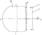
Fig. 4 is the left view of bolt screwing machine and wheel hub among Fig. 1;
Fig. 5 is the structural representation of the lathe bed of bolt screwing machine among Fig. 1;
Fig. 6 is the front view of Fig. 5 medial bed;
Fig. 7 is the vertical view of Fig. 5 medial bed;
Fig. 8 is the left view of Fig. 5 medial bed;
Fig. 9 is that the revolving bed of Fig. 5 medial bed is put in order schematic diagram in the modulation of vertical plane inward turning;
Figure 10 is after the rotation lathe bed among Fig. 9 is adjusted, and tightens axle and tightens working face relative position schematic diagram with the bolt of tightening bracing strut and wheel hub;
Figure 11 for the drive unit that rotates in a circumferential direction of the bolt screwing machine among Fig. 1, tighten axle and tighten the structural representation of bracing strut;
Figure 12 is installed on the structural representation of tightening the adjusting rod on the mount pad among Fig. 1.
Wherein the corresponding relation between Reference numeral and the component names is among Fig. 1 to Figure 12:
1 tightens axle; 11 tighten a mount pad;
2 circumferential drive units; 21 position rotaring motors; 22 rotating shafts; 23 axle sleeves; 24 installing plates;
3 tighten bracing strut; 31 move radially bar; 32 axle sleeves radially;
41 mounting bases; 42 turn tables; 43 transfer panels; 44 wheel hubs;
51 basic lathe beds; 52 lifting lathe beds; 53 leads; 54 lifts; 55 rotation lathe beds; 56 jointed shafts; 57 regulate bolt; 58 clamping screws; 59 crossbeams;
6 adjusting rods; 61 mounting brackets; 62 sliding sleeves; 63 slide bars; 64 align plate; 641 first locating surfaces; 642 second locating surfaces;
71 guide rods; 72 slide blocks; 73 screw mandrels; 74 nuts.
The specific embodiment
Core of the present utility model is for providing a kind of bolt screwing machine, and this bolt screwing machine can improve the efficient that bolt is tightened on the one hand, can improve the quality that bolt is tightened on the other hand.
In order to make those skilled in the art understand the technical solution of the utility model better, the utility model is described in further detail below in conjunction with the drawings and specific embodiments.
At first, need to prove, the utility model will be to be that example illustrates technique effect of the present utility model on the wheel hub that pitching slewing support is installed to wind-force wind-powered electricity generation machine by a plurality of bolts, and obvious bolt screwing machine provided by the utility model can also use on other workpiece that need tight a bolt.
Please refer to Fig. 1, Fig. 2, Fig. 3 and Fig. 4, Fig. 1 is the structural representation of bolt screwing machine and wheel hub among a kind of embodiment of the utility model; Fig. 2 is the front view of bolt screwing machine and wheel hub among Fig. 1; Fig. 3 is the vertical view of bolt screwing machine and wheel hub among Fig. 1; Fig. 4 is the left view of bolt screwing machine and wheel hub among Fig. 1.
As shown in Figures 1 to 4, wheel hub 44 is tightened working face along circumferentially being distributed with three bolts.In one embodiment, bolt screwing machine provided by the utility model comprise tighten the axle 1; On this basis, also comprise lathe bed (this lathe bed comprises basic lathe bed 51, lifting lathe bed 52 and rotation lathe bed 55 hereinafter described), described lathe bed is supported with the drive unit 2 that rotates in a circumferential direction, the drive unit 2 that rotates in a circumferential direction be connected with its rotation tighten bracing strut 3, tighten axle 1 and be located at and tighten on the bracing strut 3; Described bolt screwing machine also comprise all with rotate in a circumferential direction drive unit 2 with tighten axle 1 control device that is connected in bolt is tightened working face, move to each position that need tight a bolt and finish the action of tightening of bolt so that the control of described control device tightens spool 1.
Bolt screwing machine provided by the present invention is placed a side of wheel hub 44, and adjust the position of lathe bed, make that tightening the bolt that axle 1 and bolt tighten on the working face aligns.On this basis, control device sends the instruction that tights a bolt to tightening axle 1, finish tighten after, according to preset program, control device sends instruction to the drive unit 2 that rotates in a circumferential direction, and tightens axle 1 and moves to the position that the next one need tight a bolt thereby drive, and control device sends the instruction that tights a bolt to tightening axle 1 more then, so move in circles, thereby finish the work of tightening that this bolt is tightened all bolts on the working face.
In the above-mentioned course of work, the utility model has realized that the automation of a plurality of bolts tightens, the hand-held hydraulic spanner of the available technology adopting mode of tightening relatively, and the present invention has obviously improved the efficient that bolt is tightened.In addition, in the prior art, tighten mistake and cause quality problems thereby the mode of manually tightening causes easily, and the present invention is driven by control device to tighten the action of tightening that axle 1 is finished bolt automatically, thereby can significantly reduce the error that causes owing to manually-operated, and then can improve the quality of tightening of bolt effectively.
Further, as shown in Figure 1, described bolt screwing machine also comprises mounting base 41, and wheel hub 44 or other workpiece that need tight a bolt and described lathe bed are supported on the mounting base 41.The structural design of mounting base 41 provides a public installation basis for described lathe bed and wheel hub 44, guarantees that lathe bed has identical benchmark with wheel hub 44 in Z-direction, and needn't consider to install the flatness on ground.
Further, as Fig. 1, Fig. 2 and shown in Figure 4, mounting base 41 is provided with turn table 42; The workpiece that described need tight a bolt is located on the turn table 42, so that rotate under the driving of turn table 42.Turn table 42 has the function of carrying and transposition, its basic structure comprises the foundation structure part, supplies the pivoting support and the rotary motive power source of rotation, pivoting support is connected with wheel hub 44, thereby under the effect in rotary motive power source, drive hub 44 rotates in the plane that X-axis and Y-axis are determined.This kind structural design has realized the conversion that 44 3 bolts of wheel hub are tightened working face, when finish a bolt tighten all bolts in the working face tighten work after, under the effect of turn table 42, wheel hub 44 is transformed into next bolt and tightens working face.
Because the height dimension of the wheel hub 44 of different model is different, thereby need adjust the height of tightening axle 1 of bolt screwing machine this moment, thus cumbersome.In view of this, as shown in Figure 1, turn table 42 is provided with transfer panel 43, and the workpiece that described need tight a bolt is located on the transfer panel 43, and turn table 42 rotates by the workpiece that the described need of transfer panel 43 drivings tight a bolt.That is, be equipped with the transfer panel 43 of differing heights for the wheel hub 44 of different model, when making the wheel hub 44 of various models be installed on the turn table 42, its height dimension on Z-direction is consistent, thereby also just need not to adjust the height of tightening axle 1 of bolt screwing machine.
Please refer to Fig. 5, Fig. 6, Fig. 7 and Fig. 8, Fig. 5 is the structural representation of the lathe bed of bolt screwing machine among Fig. 1; Fig. 6 is the front view of Fig. 5 medial bed; Fig. 7 is the vertical view of Fig. 5 medial bed; Fig. 8 is the left view of Fig. 5 medial bed.
In above-mentioned any embodiment, can also the structure of described lathe bed be made improvements.Such as, as shown in Figure 5, described lathe bed comprises basic lathe bed 51 and is located at the lifting lathe bed 52 of basic lathe bed 51 tops that lifting lathe bed 52 supports the drive unit 2 that rotates in a circumferential direction.To this, we can specific design lifting lathe bed 52 lift in height implementations.
As Fig. 5, Fig. 6 and shown in Figure 8, be provided with a plurality of telescopic leads 53 between the bottom surface of the end face of basic lathe bed 51 and lifting lathe bed 52; Described bolt screwing machine also comprises lift 54, and an end of lift 54 is supported on the basic lathe bed 51, the bottom surface of its other end supporting elevation lathe bed 52.Basis lathe bed 51 provides a supporting role, and is fixed on the mounting base 41.As shown in Figure 5, basic lathe bed 51 links to each other with lifting lathe bed 52 by four leads 53.By regulating lift 54, adjustable lifting lathe bed 52 is along the height of Z-direction, thereby feasible center of tightening bracing strut 3 overlaps with the center that bolt is tightened working face.Lead 53 can comprise axle sleeve and the removable guide rod that is set in the pipe box, and axle sleeve is connected with basic lathe bed 51, and guide rod is connected with lifting lathe bed 52.
Please also refer to Fig. 5, Fig. 6, Fig. 7, Fig. 8, Fig. 9 and Figure 10, Fig. 9 is that the revolving bed of Fig. 5 medial bed is put in order schematic diagram in the modulation of vertical plane inward turning; Figure 10 is after the rotation lathe bed among Fig. 9 is adjusted, and tightens axle and tightens working face relative position schematic diagram with the bolt of tightening bracing strut and wheel hub.
As shown in Figure 5, lifting lathe bed 52 is further rotated and is supported with the rotation lathe bed 55 that can rotate in the vertical plane of tightening working face perpendicular to described bolt (that is plane of X-axis and the decision of Z axle), and the drive unit 2 that rotates in a circumferential direction is located on the rotation lathe bed 55.As shown in figure 10, the angle that the bolt of wheel hub 44 is tightened between working face and the Z-direction is α, on this basis, carry out bolt and tighten operation for the ease of tightening axle 1, as shown in figure 10, the rotation of α angle can take place on the plane of X-axis and the decision of Z axle in rotation lathe bed 55, thereby makes the axis normal of tightening axle 1 tighten working face in the bolt of wheel hub 44, tightens work so that carry out bolt.
To this, can a kind of structure that realizes rotating lathe bed 55 rotations of specific design.Such as, as Fig. 5, Fig. 6 and shown in Figure 7, lifting lathe bed 52 and rotation lathe bed 55 are U type spare, and rotation lathe bed 55 is located in the U type groove of lifting lathe bed 52, and the opening direction of the U type groove of rotation lathe bed 55 and lifting lathe bed 52 is identical; On this basis, hinged between the sidewall of the sidewall of rotation lathe bed 55 and corresponding lifting lathe bed 52 by jointed shaft 56.
Further, be connected with between one end of rotation lathe bed 55 diapires and the end of corresponding lifting lathe bed 52 diapires and regulate bolt 57, this adjusting bolt 57 is combined with adjusting nut, by screwing or loosening adjusting nut, can regulate the distance between the end of end of rotation lathe bed 55 diapires and corresponding lifting lathe bed 52 diapires, thereby under the effect of jointed shaft 56, make rotation lathe bed 55 rotate.
After making that rotation lathe bed 55 rotates to suitable angle, can locate better, as shown in Figure 5 and Figure 6, the sidewall of rotation lathe bed 55 is equipped with the corresponding long through-hole in a plurality of positions with lifting lathe bed 52 sidewalls, and each long through-hole is symmetrically distributed in the both sides of jointed shaft 56, and each long through-hole that is in jointed shaft 56 both sides is along with the length of distance jointed shaft 56 its major axis far away more is long more; Long through-hole on the sidewall of the lifting lathe bed 52 that the long through-hole on the sidewall of rotation lathe bed 55 is corresponding with the position has passed clamping screw 58.After rotation lathe bed 55 needs the anglec of rotation, the clamping screw in each slotted hole 58 is unclamped, after the suitable angle of rotation lathe bed 55 rotations, and then with each clamping screw 58 lockings.
Please refer to Figure 11 and Figure 12, Figure 11 for the drive unit that rotates in a circumferential direction of the bolt screwing machine among Fig. 1, tighten axle and tighten the structural representation of bracing strut; Figure 12 is installed on the structural representation of tightening the adjusting rod on the mount pad among Fig. 1.
As shown in figure 11, tighten bracing strut 3 and be connected with and tighten a mount pad 11, tighten axle 1 and be located at and tighten on the mount pad 11; On this basis, tighten and further be provided with the adjusting rod 6 of measuring rotation lathe bed 55 anglecs of rotation on the mount pad 11, the effect of this adjusting rod 6 is to be used for qualitative definite rotation lathe bed 55 whether to have rotated suitable angle.
Particularly, as shown in figure 12, adjusting rod 6 comprises and tightens mounting bracket 61, the sliding sleeve 62 that is connected with mounting bracket 61 that a mount pad 11 is connected and be located at slide bar 63 in the sliding sleeve 62, and the axis of slide bar 63 is parallel to the axis of tightening axle 1; The end of slide bar 63 is provided with and aligns plate 64, aligns plate 64 and is provided with perpendicular to slide bar 63 axis and with described bolt and tightens relative first locating surface 641 of working face.During work, slide bar 63 is skidded off from sliding sleeve 62, as Fig. 1 and shown in Figure 11, making first locating surface 641 that aligns plate 64 tighten working face with bolt contacts, rotate lathe bed 55 this moment and begin rotation, till first locating surface 641 and bolt were tightened working face and fitted fully, tightened the axis normal of axle 1 just and tighten working face in bolt this moment, tightens work thereby carry out bolt.Obviously, the structural design of this adjusting rod 6 has realized the control to rotation lathe bed 55 anglecs of rotation easily, and simple in structure, low cost of manufacture.
As shown in figure 11, the quantity of adjusting rod 6 is two, and the two is located at respectively and tightens the tightening on the mount pad 11 of bracing strut 3 two ends; As shown in figure 12, align plate 64 and be the L template, first locating surface 641 is located on the riser of described L template, and further is provided with on the transverse slat of described L template and second vertical and relative with the inner ring of the pivoting support locating surface 642 of first locating surface 641.During work, will tighten bracing strut 3 and rotate to Z-direction, adjusting lift 54 makes tightens axle 1 along rising of Z axle or decline.Simultaneously, distance between the pivoting support inner ring on second locating surface 642 that aligns plate 64 on the measurement adjusting lever 6 and the wheel hub 44, if distance is identical between two second locating surfaces 642 and the corresponding inner ring anchor ring, can think that the tightening machine height regulates the arrival tram.
Need to prove, carry out the angular adjustment of revolving bed body 55 earlier, wait regulate put in place after, tighten the height of axle 1 again and regulate.
In the above-described embodiments, can also be further improved.Such as, as shown in Figure 5, two sidewalls of rotation lathe bed 55 all are supported with on 59, two crossbeams 59 of crossbeam and are equipped with guide rod 71, and circumferentially drive unit 2 is supported on two guide rods 71 movably.This kind structural design can realize more easily tightening axle 1 near or tighten working face away from bolt.
Particularly, as shown in figure 11, circumferentially drive unit 2 comprises position rotaring motor 21 and the rotating shaft 22 that is driven by position rotaring motor 21, rotating shaft 22 with tighten bracing strut 3 and be connected; The outer rotatable of rotating shaft 22 is set with axle sleeve 23, and axle sleeve 23 is fixing vertically with rotating shaft 22, and axle sleeve 23 is supported on the guide rod 71 movably.This kind structural design realize tightening axle 1 near or tighten away from bolt on the basis of working face, also realized tightening the rotation of bracing strut 3 more easily, move to the position that any need tight a bolt thereby be convenient to tighten axle 1.
Further, as shown in Figure 5, guide rod 71 is provided with slide block 72; As shown in figure 11, axle sleeve 23 is connected with installing plate 24, and installing plate 24 is fixedlyed connected with slide block 72.In addition, further be provided with feed screw nut's device in the U type groove of rotation lathe bed 55, the screw mandrel 73 of described feed screw nut's device is connected with the output shaft of drive motors, and the nut 74 of described feed screw nut's device is fixedlyed connected with installing plate 24.Obviously, the further specific implementation of this kind structural design tighten axle 1 near or tighten working face away from bolt.
In addition, can in the periphery of different radii, carry out bolt and tighten operation, tighten bracing strut 3 and further be connected with the radiai adjustment device for the ease of tightening axle 1, tighten bracing strut 3 by described radiai adjustment device with tighten spool 1 and be connected.Particularly, as shown in figure 11, described radiai adjustment device comprises and moves radially bar 31, and the outer cover that moves radially bar 31 is equipped with movably radially axle sleeve 32, tightens bracing strut 3 and is connected with axle sleeve 32 radially, tightens axle 1 and moves radially bar 31 and be connected.
More than a kind of bolt screwing machine provided by the utility model is described in detail.Used specific case herein principle of the present utility model and embodiment are set forth, the explanation of above embodiment just is used for helping to understand method of the present utility model and core concept thereof.Should be understood that; for those skilled in the art; under the prerequisite that does not break away from the utility model principle, can also carry out some improvement and modification to the utility model, these improvement and modification also fall in the protection domain of the utility model claim.
Claims (19)
1. a bolt screwing machine comprises and tightens axle (1); It is characterized in that, described bolt screwing machine also comprises lathe bed, described lathe bed is supported with the drive unit that rotates in a circumferential direction (2), the described drive unit that rotates in a circumferential direction (2) be connected with its rotation tighten bracing strut (3), the described axle (1) of tightening is located at and is describedly tightened that bracing strut (3) is gone up and move in bolt is tightened working face with the described bracing strut (3) of tightening; Described bolt screwing machine also comprises all with the described drive unit that rotates in a circumferential direction (2) tightens the control device that axle (1) is connected with described.
2. bolt screwing machine as claimed in claim 1 is characterized in that, described bolt screwing machine also comprises mounting base (41), and workpiece that need tight a bolt and described lathe bed are supported on the described mounting base (41).
3. bolt screwing machine as claimed in claim 2 is characterized in that, described mounting base (41) is provided with turn table (42); The workpiece that described need tight a bolt is located at (42) on the described turn table, so that rotate under the driving of described turn table (42).
4. bolt screwing machine as claimed in claim 3, it is characterized in that, described turn table (42) is provided with transfer panel (43), the workpiece that described need tight a bolt is located on the described transfer panel (43), and described turn table (42) rotates by the workpiece that the described need of described transfer panel (43) driving tight a bolt.
5. bolt screwing machine as claimed in claim 1 is characterized in that, described lathe bed comprises basic lathe bed (51) and be located at the lifting lathe bed (52) of described basic lathe bed (51) top that described lifting lathe bed (52) supports the described drive unit that rotates in a circumferential direction (2).
6. bolt screwing machine as claimed in claim 5 is characterized in that, is provided with a plurality of telescopic leads (53) between the bottom surface of the end face of described basic lathe bed (51) and described lifting lathe bed (52); Described bolt screwing machine also comprises lift (54), and an end of described lift (54) is supported on the described basic lathe bed (51), and its other end supports the bottom surface of described lifting lathe bed (52).
7. bolt screwing machine as claimed in claim 5, it is characterized in that, described lifting lathe bed (52) is further rotated and is supported with and can tightening the rotation lathe bed (55) that rotates in the vertical plane of working face perpendicular to described bolt, and the described drive unit that rotates in a circumferential direction (2) is located on the described rotation lathe bed (55).
8. bolt screwing machine as claimed in claim 7, it is characterized in that, described lifting lathe bed (52) and described rotation lathe bed (55) are U type spare, described rotation lathe bed (55) is located in the U type groove of described lifting lathe bed (52), and the opening direction of the U type groove of described rotation lathe bed (55) and described lifting lathe bed (52) is identical; Hinged between the sidewall of the sidewall of described rotation lathe bed (55) and corresponding described lifting lathe bed (52) by jointed shaft (56).
9. bolt screwing machine as claimed in claim 8 is characterized in that, is connected with between the end of an end of described rotation lathe bed (55) diapire and corresponding described lifting lathe bed (52) diapire to regulate bolt (57).
10. bolt screwing machine as claimed in claim 8, it is characterized in that, the sidewall of described rotation lathe bed (55) is equipped with the corresponding long through-hole in a plurality of positions with the sidewall of described lifting lathe bed (52), and each long through-hole is symmetrically distributed in the both sides of described jointed shaft (56), and each long through-hole that is in described jointed shaft (56) both sides is along with the length of distance described jointed shaft (56) its major axis far away more is long more; Long through-hole on the sidewall of the described lifting lathe bed (52) that the long through-hole on the sidewall of described rotation lathe bed (55) is corresponding with the position has passed clamping screw (58).
11., it is characterized in that the described bracing strut (3) of tightening is connected with and tightens a mount pad (11) as each described bolt screwing machine of claim 7 to 10, the described axle (1) of tightening is located at described tightening on the mount pad (11); Described tightening further is provided with the adjusting rod (6) of measuring described rotation lathe bed (55) anglec of rotation on the mount pad (11).
12. bolt screwing machine as claimed in claim 11, it is characterized in that, described adjusting rod (6) comprises with described to be tightened mounting bracket (61), the sliding sleeve (62) that is connected with described mounting bracket (61) that a mount pad (11) is connected and is located at slide bar (63) in the described sliding sleeve (62), and the axis of described slide bar (63) is parallel to the described axis of tightening axle (1); The end of described slide bar (63) is provided with and aligns plate (64), and the described plate (64) that aligns is provided with perpendicular to described slide bar (63) axis and with described bolt and tightens relative first locating surface of working face (641).
13. bolt screwing machine as claimed in claim 12 is characterized in that, the quantity of described adjusting rod (6) is two, and the two is located at described the tightening on the mount pad (11) of bracing strut (3) two ends of tightening respectively; The described plate (64) that aligns is the L template, described first locating surface (641) is located on the riser of described L template, and further is provided with vertical with described first locating surface (641) and relative with the inner ring of pivoting support second locating surface (642) on the transverse slat of described L template.
14. as the described bolt screwing machine of claim 8 to 10, it is characterized in that, two sidewalls of described rotation lathe bed (55) all are supported with crossbeam (59), be equipped with guide rod (71) on two described crossbeams (59), described circumferential drive unit (2) is supported on two described guide rods (71) movably.
15. bolt screwing machine as claimed in claim 14 is characterized in that, described circumferential drive unit (2) comprises position rotaring motor (21) and the rotating shaft (22) that is driven by described position rotaring motor (21), and described rotating shaft (22) is connected with the described bracing strut (3) of tightening; The outer rotatable of described rotating shaft (22) is set with axle sleeve (23), and described axle sleeve (23) is supported on the described guide rod (71) movably.
16. bolt screwing machine as claimed in claim 15 is characterized in that, described guide rod (71) is provided with slide block (72), and described axle sleeve (23) is connected with installing plate (24), and described installing plate (24) is fixedlyed connected with described slide block (72).
17. bolt screwing machine as claimed in claim 16, it is characterized in that, further be provided with feed screw nut's device in the U type groove of described rotation lathe bed (55), the screw mandrel of described feed screw nut's device (73) is connected with the output shaft of drive motors, and the nut of described feed screw nut's device (74) is fixedlyed connected with described installing plate (24).
18., it is characterized in that the described bracing strut (3) of tightening further is connected with the radiai adjustment device as each described bolt screwing machine of claim 1 to 10, the described bracing strut (3) of tightening is connected with the described axle (1) of tightening by described radiai adjustment device.
19. bolt screwing machine as claimed in claim 18, it is characterized in that, described radiai adjustment device comprises and moves radially bar (31), the described outer cover that moves radially bar (31) is equipped with movably radially axle sleeve (32), the described bracing strut (3) of tightening is connected with described radially axle sleeve (32), and the described axle (1) of tightening is connected with the described bar (31) that moves radially.
Priority Applications (1)
| Application Number | Priority Date | Filing Date | Title |
|---|---|---|---|
| CN2010205862276U CN201824125U (en) | 2010-10-27 | 2010-10-27 | Bolt tightening machine |
Applications Claiming Priority (1)
| Application Number | Priority Date | Filing Date | Title |
|---|---|---|---|
| CN2010205862276U CN201824125U (en) | 2010-10-27 | 2010-10-27 | Bolt tightening machine |
Publications (1)
| Publication Number | Publication Date |
|---|---|
| CN201824125U true CN201824125U (en) | 2011-05-11 |
Family
ID=43962683
Family Applications (1)
| Application Number | Title | Priority Date | Filing Date |
|---|---|---|---|
| CN2010205862276U Expired - Fee Related CN201824125U (en) | 2010-10-27 | 2010-10-27 | Bolt tightening machine |
Country Status (1)
| Country | Link |
|---|---|
| CN (1) | CN201824125U (en) |
Cited By (16)
| Publication number | Priority date | Publication date | Assignee | Title |
|---|---|---|---|---|
| CN103028936A (en) * | 2012-12-19 | 2013-04-10 | 葛双好 | Double-nut tightening device with automatic counting function |
| CN103240587A (en) * | 2013-04-02 | 2013-08-14 | Tcl海外电子(惠州)有限公司 | Automatic screw locking device |
| CN104325283A (en) * | 2014-10-27 | 2015-02-04 | 北京金风科创风电设备有限公司 | Bolt fastening device |
| CN104551640A (en) * | 2014-12-29 | 2015-04-29 | 中国第一重型机械股份公司 | Full-station bolt stretcher |
| CN104924063A (en) * | 2015-07-03 | 2015-09-23 | 西南石油大学 | Rapid flange connector |
| CN107520599A (en) * | 2016-06-22 | 2017-12-29 | 上海新宇箴诚电控科技有限公司 | A kind of device that screw is tightened for any angle |
| CN107538210A (en) * | 2017-09-29 | 2018-01-05 | 新疆金风科技股份有限公司 | Bolt clamp device and its operating method |
| CN107877437A (en) * | 2017-10-26 | 2018-04-06 | 国电联合动力技术(保定)有限公司 | A kind of wind power hub pitch variable bearings automatic screwing down apparatus |
| CN109732333A (en) * | 2019-03-18 | 2019-05-10 | 南京灵雀智能制造有限公司 | A kind of multi-model screws device for screwing up and its application method |
| CN109968013A (en) * | 2019-05-02 | 2019-07-05 | 国电联合动力技术(赤峰)有限公司 | Wind power hub assembly line system |
| CN110848089A (en) * | 2019-11-19 | 2020-02-28 | 新疆金风科技股份有限公司 | Installation jig, method for installing tower drum accessory and tower drum equipment |
| CN111486059A (en) * | 2020-05-09 | 2020-08-04 | 国电联合动力技术(连云港)有限公司 | Automatic locking device for bearing of wind driven generator |
| CN111656009A (en) * | 2017-12-06 | 2020-09-11 | 维斯塔斯风力系统有限公司 | Automatic tightening of bolts |
| CN114083279A (en) * | 2021-12-13 | 2022-02-25 | 中国航发南方工业有限公司 | Symmetrical fastener tightening device |
| CN115122081A (en) * | 2021-03-26 | 2022-09-30 | 西门子歌美飒可再生能源公司 | Tightening device |
| CN116922065A (en) * | 2023-07-26 | 2023-10-24 | 广东百能家居有限公司 | Automatic implantation device and method for rivet nut of stainless steel cabinet plate |
-
2010
- 2010-10-27 CN CN2010205862276U patent/CN201824125U/en not_active Expired - Fee Related
Cited By (21)
| Publication number | Priority date | Publication date | Assignee | Title |
|---|---|---|---|---|
| CN103028936A (en) * | 2012-12-19 | 2013-04-10 | 葛双好 | Double-nut tightening device with automatic counting function |
| CN103240587A (en) * | 2013-04-02 | 2013-08-14 | Tcl海外电子(惠州)有限公司 | Automatic screw locking device |
| CN104325283A (en) * | 2014-10-27 | 2015-02-04 | 北京金风科创风电设备有限公司 | Bolt fastening device |
| CN104551640A (en) * | 2014-12-29 | 2015-04-29 | 中国第一重型机械股份公司 | Full-station bolt stretcher |
| CN104551640B (en) * | 2014-12-29 | 2017-03-08 | 中国第一重型机械股份公司 | Full work station bolt stretching machine |
| CN104924063A (en) * | 2015-07-03 | 2015-09-23 | 西南石油大学 | Rapid flange connector |
| CN107520599A (en) * | 2016-06-22 | 2017-12-29 | 上海新宇箴诚电控科技有限公司 | A kind of device that screw is tightened for any angle |
| CN107520599B (en) * | 2016-06-22 | 2024-04-16 | 上海新宇箴诚电控科技有限公司 | Device for screwing screw at any angle |
| CN107538210A (en) * | 2017-09-29 | 2018-01-05 | 新疆金风科技股份有限公司 | Bolt clamp device and its operating method |
| CN107538210B (en) * | 2017-09-29 | 2020-01-31 | 新疆金风科技股份有限公司 | Bolt fastening device and operation method thereof |
| CN107877437A (en) * | 2017-10-26 | 2018-04-06 | 国电联合动力技术(保定)有限公司 | A kind of wind power hub pitch variable bearings automatic screwing down apparatus |
| CN111656009A (en) * | 2017-12-06 | 2020-09-11 | 维斯塔斯风力系统有限公司 | Automatic tightening of bolts |
| US11292094B2 (en) | 2017-12-06 | 2022-04-05 | Vestas Wind Systems A/S | Automated tightening of bolts |
| CN109732333A (en) * | 2019-03-18 | 2019-05-10 | 南京灵雀智能制造有限公司 | A kind of multi-model screws device for screwing up and its application method |
| CN109968013A (en) * | 2019-05-02 | 2019-07-05 | 国电联合动力技术(赤峰)有限公司 | Wind power hub assembly line system |
| CN110848089A (en) * | 2019-11-19 | 2020-02-28 | 新疆金风科技股份有限公司 | Installation jig, method for installing tower drum accessory and tower drum equipment |
| CN111486059A (en) * | 2020-05-09 | 2020-08-04 | 国电联合动力技术(连云港)有限公司 | Automatic locking device for bearing of wind driven generator |
| CN115122081A (en) * | 2021-03-26 | 2022-09-30 | 西门子歌美飒可再生能源公司 | Tightening device |
| CN114083279A (en) * | 2021-12-13 | 2022-02-25 | 中国航发南方工业有限公司 | Symmetrical fastener tightening device |
| CN114083279B (en) * | 2021-12-13 | 2022-11-29 | 中国航发南方工业有限公司 | Symmetrical fastener tightening device |
| CN116922065A (en) * | 2023-07-26 | 2023-10-24 | 广东百能家居有限公司 | Automatic implantation device and method for rivet nut of stainless steel cabinet plate |
Similar Documents
| Publication | Publication Date | Title |
|---|---|---|
| CN201824125U (en) | Bolt tightening machine | |
| CN101890635B (en) | Bolt tightening machine for connecting slewing bearing and hub | |
| CN201325978Y (en) | Self-centering and positioning clamping device | |
| CN201570183U (en) | Bolt and nut tightening operation training platform | |
| CN109483464A (en) | A kind of industrial instrument disk assembly bench and its assembly method | |
| CN102000937B (en) | Synchronous self-centering multi-claw chuck type welded part horizontally rotating device and using method thereof | |
| CN201224010Y (en) | Overlaying welding auxiliary device of horomill press roll and backing block | |
| CN211447795U (en) | Special clamp for plastic building template | |
| CN110936766B (en) | Mechanical arm for replacing tire | |
| CN111775639A (en) | Aircraft tire torque device | |
| CN205704517U (en) | A kind of construction planing means | |
| CN213245100U (en) | Anchor clamps fixed knot that digit control machine tool was used constructs | |
| CN102879194B (en) | Adjustable support structure of transmission test bed | |
| CN201971435U (en) | Capacitor loading and turnover mechanism | |
| CN101323076B (en) | Overlaying welding auxiliary device of horomill press roll and backing block | |
| CN102357765B (en) | Rotary welding device | |
| CN201841393U (en) | Synchronous self-centering multi-claw chuck type weldment horizontal rotating device | |
| CN208067704U (en) | The gantry frame type bearing automatic installation apparatus of wind power hub Intelligent assembly line | |
| CN211075206U (en) | Positioning structure is used in processing of many specifications carton color printing device | |
| CN210998569U (en) | Flange plate machining table with tool clamp mechanism | |
| CN204858429U (en) | Cable traction frame | |
| CN202763317U (en) | Automatic beveling and welding device | |
| CN106743914A (en) | A kind of rotating disc type strippers of paper guide | |
| CN203018982U (en) | Movable tire for circular-seam welding of pipes | |
| CN212267163U (en) | Aircraft tire torque device |
Legal Events
| Date | Code | Title | Description |
|---|---|---|---|
| C14 | Grant of patent or utility model | ||
| GR01 | Patent grant | ||
| C17 | Cessation of patent right | ||
| CF01 | Termination of patent right due to non-payment of annual fee |
Granted publication date: 20110511 Termination date: 20121027 |