CN201805452U - Wireless unvarnished transmission device based on wireless network - Google Patents
Wireless unvarnished transmission device based on wireless network Download PDFInfo
- Publication number
- CN201805452U CN201805452U CN2010201091700U CN201020109170U CN201805452U CN 201805452 U CN201805452 U CN 201805452U CN 2010201091700 U CN2010201091700 U CN 2010201091700U CN 201020109170 U CN201020109170 U CN 201020109170U CN 201805452 U CN201805452 U CN 201805452U
- Authority
- CN
- China
- Prior art keywords
- wireless
- module
- frame
- network
- power supply
- Prior art date
- Legal status (The legal status is an assumption and is not a legal conclusion. Google has not performed a legal analysis and makes no representation as to the accuracy of the status listed.)
- Expired - Fee Related
Links
Images

Abstract
The utility model relates to a concentrated meter reading system for a wireless network, in particular to a wireless unvarnished transmission device based on a wireless network. The wireless unvarnished transmission device is installed in an electric meter concentrator and comprises a wireless unvarnished transmission module, an indicating lamp, a power processing module, a level conversion module and a power output module; the wireless unvarnished transmission module performs serial communication with a central processing unit in the electric meter concentrator through the level conversion module and also performs communication with an electric meter at a user terminal through a wireless network; a working power supply terminal of the wireless unvarnished transmission module is used for receiving the externally supplied power through the power processing module; the output terminal of the power processing module is connected with an opto-coupler in the electric meter concentrator through the power output module; and the indicating lamp is connected to the output terminal of the wireless unvarnished transmission module. By adopting the wireless method for periodically performing concentrated meter reading, the wireless unvarnished transmission device not only improves the working efficiency, reduces the failures under manual reading, but also saves the cost greatly and also can realize the automatic control.
Description
Technical field
The utility model relates to the wireless network automatic meter reading system, is a kind of wireless transparent transmission equipment based on wireless network specifically.
Background technology
At present, China power marketing department adopts manual type to obtain user's electricity consumption data, promptly makes an inventory ammeter from door to door by meter reading personnel every month or every some months.This traditional approach brings great inconvenience for power marketing department and user, and poor in timeliness, big, the artificial randomness of statistical computation workload have consumed great amount of manpower and material resources and financial resources greatly, can not adapt to modernization of power marketing department and informationalized requirement.At this situation, national departments concerned proposes later general and progressively replaces traditional manual metering based on the Automatic meter reading system of computer.
At this situation, national departments concerned proposes later general and progressively replaces traditional manual metering based on the Automatic meter reading system of computer.The long distance wireless centralized meter-reading system is that the modern wireless communication technique of collection, computer hardware technique, electric energy metrical technology and power marketing technology are the comprehensive real-time information collection and the analysis process system of the need for electricity of one.Shown in Figure 1, be the long-distance meter-reading system block diagram.It sets up contact by specific Wireless Telecom Equipment, does not need personnel to reach the spot and just can finish the intellectualized management system of copy reading user power utilization amount.In recent years, this technology is at home and abroad arisen at the historic moment, and develops very fast.Its final purpose is automatically, concentrates, periodically makes a copy of each user's power consumption that this has crucial meaning undoubtedly for the managerial skills and the economic benefit that improve power department.
At present, the ZigBee technology be a kind of closely, low complex degree, low-power consumption, two-way wireless communication technology cheaply, be the technology of one group of relevant networking, safety and application software aspect of developing based on the IEEE802.15.4 wireless standard.It supports 3 kinds of main ad hoc deployed wireless networks types, i.e. hub-and-spoke configuration, network structure and bunch shape structure.Can be by how forming the wireless data sending network, the hundreds of rice that the distance between each network node can reach to 65000 wireless data transmission modules.Wireless data transmission rate is up to 250kb/s.
The ZigBee technology can solve a series of problems such as wireless communication technique in the long distance wireless centralized meter-reading system, computer hardware technique, electric energy metrical technology and power marketing technology well, can overcome big, artificial random big etc. the deficiency of poor in timeliness, statistical computation workload.And the wireless network ammeter concentrator based on ZigBee that can address the above problem does not at present appear in the newspapers as yet.
The utility model content
At the poor real time data acquisition that exists in the prior art, be not easy to deficiency such as centralized management, the technical problems to be solved in the utility model provided a kind of ageing good, stop artificial randomness, reduce not enough wireless transparent transmission equipment such as hand labor intensity based on wireless network.
For what solve the problems of the technologies described above, the technical solution adopted in the utility model is:
The utility model is installed in the ammeter concentrator based on the wireless transparent transmission equipment of wireless network, comprises wireless transparent transmission module, indicator light, power supply processing module, level switch module and power supply output module; Wherein, the central processing unit of wireless transparent transmission module in level switch module and ammeter concentrator carries out serial communication, wireless transparent transmission module communicates by wireless network and user terminal ammeter, the working power end of wireless transparent transmission module receives outer power supply source by power supply processing module, and the output of power supply processing module also passes through the power supply output module and links to each other with optocoupler in the ammeter concentrator; The output of wireless transparent transmission module is connected to indicator light.
The communication protocol of described wireless transparent transmission module comprises application layer, network layer and data link layer, and wherein: described application layer receives the data of self terminal ammeter, and the data that received are carried out encapsulate forwarded according to defined application layer frame format; Application layer is being resolved the data of receiving, carries out the application layer operation according to the content of data;
Described network layer receives application layer data, and the data that received are carried out encapsulate forwarded according to defined network layer frames form; Network layer is being resolved the data of receiving, carries out the network layer operation according to the content of data;
Described data link layer receives the data of network layer, and the data that received are carried out encapsulate forwarded according to defined data link layer frame format.
The frame header branch of described application layer frame format comprises: frame control field, sequence-number field and command field, and wherein, frame control field is 8 bit fields, indication application layer frame is claim frame or response frame; Sequence-number field is that the frame header of application layer frame format is divided the transmission sequence number; Command field indication application layer frame ordering type comprises and obtains the item command frame, the item command frame is set, sampling period command frame and data issue an order frame are set.
The frame header branch of described network layer frames form comprises: frame control field, destination address field (DAF), source address field, and wherein, frame control field is 8 bit fields, indication network layer frame type comprises that Frame, short address request for allocation frame and short address are provided with frame; Destination address field (DAF) is for sending the address of this frame to destination device; Source address field is the address of the equipment of this frame of transmission.
The frame header branch of described data link layer frame format comprises: frame control field, sequence-number field, network identity field, destination address field (DAF) and source address field, wherein, frame control field is 8 bit fields, designation data link-layer frame type, judge whether need to confirm and address style information, comprise Frame, Network Synchronization frame, synchronizing detection frame and acknowledgement frame; Sequence-number field is that the frame header of this data link layer frame format is divided the transmission sequence number; The network identity field is the sign of the equipment place network of this frame of transmission; Destination address field (DAF) is for sending the address of this frame to destination device; Source address field is the address of the equipment of this frame of transmission.
The utlity model has following advantage:
1. intelligent meter data recording., do not adopt wireless mode to carry out regular centralized automatic meter-reading, promptly improved operating efficiency, reduced artificial mistake again and copied, also saved cost greatly adopting artificial mode to carry out checking meter from house to house.
2. can realize automation control.Monitor by the electricity consumption situation that the host computer at management of power use center can be real-time, be convenient to maintenance and management the user.
3. telecommunication.Adopt the frequency range of 2.4GHz, the outdoor communication distance can reach 1000 meters.
4. directly perceived the demonstration.The utility model is during based on the wireless network ammeter concentrator operate as normal of ZigBee, and the staff can confirm whether the downlink communication part is working properly by the state of watching the wireless communication section indicator light on the concentrator fully.
5. the ammeter concentrator of employing wireless transparent transmission module makes the ammeter mounting arrangements of whole system flexible.Reduce a large amount of house wiring, saved installation cost.
6. can externally provide 5V/100mA voltage, use for external equipment.
Description of drawings
Fig. 1 is applied to the topological diagram of long distance wireless centralized meter-reading system for the utility model wireless network ammeter concentrator;
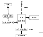
Fig. 2 is the electrical structure block diagram of the utility model based on the wireless transparent transmission equipment of wireless network;
Fig. 3 is the circuit theory diagrams of the utility model remote wireless meter recording concentrator;
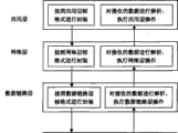
Fig. 4 is the wireless network communication protocol formation schematic diagram of the utility model based on the wireless transparent transmission equipment of wireless network;
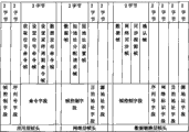
Fig. 5 is the wireless network protocol stack frame format schematic diagram of the utility model based on the wireless transparent transmission equipment of wireless network.
Embodiment
Below in conjunction with accompanying drawing the utility model is described in further detail.
As shown in Figure 1, the utility model is applied to the wireless network ammeter concentrator of long distance wireless centralized meter-reading system, the ammeter concentrator carries out data communication by GPRS network and user management central master station, comprise wireless transparent transmission equipment in the ammeter concentrator, wireless transparent transmission module in the wireless transparent transmission equipment is according to the radio meter register terminal in ZigBee agreement and the wireless network, and promptly the user terminal ammeter communicates.Zigbee, be translated in China " purple honeybee ", it and bluetooth are similar, be a kind of highly reliable wireless data sending network, the Zigbee digital transmission module is similar to the mobile network base station, can be how to 65000 wireless data transmission modules, in whole network range, can intercom mutually between each Zigbee network digital transmission module, communication distance from the 75m of standard to hundreds of rice, several kilometers, and support infinite expanding.ZigBee is as a kind of emerging communication technology, has closely, characteristics such as low complex degree, low-power consumption, low data rate, low cost.
The basis of ZigBee application layer and network layer protocol is the IEEE802.15.4 standard, it be a kind of economy, efficient, low data rate (<250kbps), be operated in the wireless technology of 2.4GHz and 868/928MHz, be used for personal area network and peer-to-peer network.
Shown in Fig. 2 and 3, the utility model is based on the wireless transparent transmission equipment of wireless network, comprise that (present embodiment adopts AMS1117 and LM2576 for wireless transparent transmission module U1 (present embodiment adopts the 3.3V power supply that it is powered), indicator light LED1~LED5, power supply processing module and power supply output module, wherein, LM2576 is made of power supply processing module 5V and power supply output module, effect is that the 12V power source conversion with externally fed is the 5V power supply, and optocoupler is powered; AMS1117 powers to wireless transparent transmission module for power supply processing module 3.3V effect is to be the 3.3V power supply with the 5V power source conversion), level switch module (present embodiment adopts SN74LV07ANSR).
Wherein, the central processing unit of wireless transparent transmission module in level switch module and ammeter concentrator carries out serial communication, wireless transparent transmission module communicates by wireless network and user terminal ammeter, the working power end of wireless transparent transmission module receives outer power supply source by power supply processing module, and the output of power supply processing module also links to each other with optocoupler (present embodiment employing 5V power supply is powered to it) in the ammeter concentrator by the power supply output module; The output of wireless transparent transmission module is connected to indicator light.
As shown in Figure 4, the utility model comprises application layer, network layer and data link layer based on the communication protocol of the wireless transparent transmission equipment of wireless network, wherein: described application layer receives the data of self terminal ammeter, and the data that received are carried out encapsulate forwarded according to defined application layer frame format; Application layer is being resolved the data of receiving, carries out the application layer operation according to the content of data;
Described network layer receives application layer data, and the data that received are carried out encapsulate forwarded according to defined network layer frames form; Network layer is being resolved the data of receiving, carries out the network layer operation according to the content of data;
Described data link layer receives the data of network layer, and the data that received are carried out encapsulate forwarded according to defined data link layer frame format.
As shown in Figure 5, the utility model comprises based on the frame header branch of application layer frame format in the communication protocol of the wireless transparent transmission equipment of wireless network: frame control field, sequence-number field and command field, wherein, frame control field is 8 bit fields, and indication application layer frame is claim frame or response frame; Sequence-number field is that the frame header of this application layer frame format is divided the transmission sequence number; Command field indication application layer frame ordering type comprises and obtains the item command frame, the item command frame is set, sampling period command frame and data issue an order frame are set.
The frame header branch of network layer frames form comprises: frame control field, destination address field (DAF), source address field, and wherein, frame control field is 8 bit fields, indication network layer frame type comprises that Frame, short address request for allocation frame and short address are provided with frame; Destination address field (DAF) is for sending the address of this frame to destination device; Source address field is the address of the equipment of this frame of transmission.
The frame header branch of data link layer frame format comprises: frame control field, sequence-number field, network identity field, destination address field (DAF) and source address field, wherein, frame control field is 8 bit fields, designation data link-layer frame type, judge whether need to confirm and address style information, comprise Frame, Network Synchronization frame, synchronizing detection frame and acknowledgement frame; Sequence-number field is that this data link layer frame header is divided the transmission sequence number; The network identity field is the sign of the equipment place network of this frame of transmission; Destination address field (DAF) is for sending the address of this frame to destination device; Source address field is the address of the equipment of this frame of transmission.
The indicator light that the output of wireless transparent transmission module connects is used for the operating state of display radio transparent transmission module, and comprising: whether normally power on indication, radio-frequency receiving-transmitting indication and the indication of radio frequency network state.
After system powers on, the wireless module operate as normal, whether normal power on indicator light bright (red light);
When transfer of data, the radio-frequency receiving-transmitting indicator light is bright, and this lamp is a red and green color, and during blinking red lamp, representation module receives data; During the green light flicker, representation module sends data;
Radio communication is normal, radio frequency network status indicator lamp flicker (green light).
Operation principle of the present utility model is as follows:
After system powers on, wireless transparent transmission module operate as normal, serial communication is working properly.Wireless transparent transmission module in the ammeter concentrator will be on time, regularly carry out data acquisition from the electric supply meter terminal by wireless mode, and the data that collect are passed to central processing unit in the concentrator by serial mode, central processing unit in the concentrator passes to management of power use central master station with the data that the collect mode by GPRS, carry out back-up processing, in case the mode of GPRS takes place unusually, central processing unit will pass to management of power use central master station by the mode of Ethernet with the data that collect, and carry out back-up processing.
Wherein, wireless communication module operation wireless communication protocol stack, wireless communication protocol stack comprise the transmission with data and application layer, network layer and the data link layer of receiving function;
Application layer is responsible for the communication and the maintenance function of application layer.The frame header branch of application layer frame format comprises: frame control field, sequence-number field and command field, and wherein, frame control field is 8 bit fields, indication application layer frame is claim frame or response frame; Sequence-number field is that the frame header of application layer frame format is divided the transmission sequence number; Command field indication application layer frame ordering type comprises and obtains the item command frame, the item command frame is set, sampling period command frame and data issue an order frame are set.
Network layer is responsible for the communication and the maintenance function of network layer.The frame header branch of network layer frames form comprises: frame control field, destination address field (DAF), source address field, and wherein, frame control field is 8 bit fields, indication network layer frame type comprises that Frame, short address request for allocation frame and short address are provided with frame; Destination address field (DAF) is for sending the address of this frame to destination device; Source address field is the address of the equipment of this frame of transmission.
Data link layer is responsible for the communication and the maintenance function of data link layer.The frame header branch of data link layer frame format comprises: frame control field, sequence-number field, network identity field, destination address field (DAF) and source address field, wherein, frame control field is 8 bit fields, designation data link-layer frame type, judge whether need to confirm and address style information, comprise Frame, Network Synchronization frame, synchronizing detection frame and acknowledgement frame; Sequence-number field is that the frame header of the frame format of this data link layer frame is divided the transmission sequence number; The network identity field is the sign of the equipment place network of this frame of transmission; Destination address field (DAF) is for sending the address of this frame to destination device; Source address field is the address of the equipment of this frame of transmission.
Claims (1)
1. the wireless transparent transmission equipment based on wireless network is installed in the ammeter concentrator, it is characterized in that: comprise wireless transparent transmission module, indicator light, power supply processing module, level switch module and power supply output module; Wherein, the central processing unit of wireless transparent transmission module in level switch module and ammeter concentrator carries out serial communication, wireless transparent transmission module communicates by wireless network and user terminal ammeter, the working power end of wireless transparent transmission module receives outer power supply source by power supply processing module, and the output of power supply processing module also passes through the power supply output module and links to each other with optocoupler in the ammeter concentrator; The output of wireless transparent transmission module is connected to indicator light.
Priority Applications (1)
| Application Number | Priority Date | Filing Date | Title |
|---|---|---|---|
| CN2010201091700U CN201805452U (en) | 2010-02-05 | 2010-02-05 | Wireless unvarnished transmission device based on wireless network |
Applications Claiming Priority (1)
| Application Number | Priority Date | Filing Date | Title |
|---|---|---|---|
| CN2010201091700U CN201805452U (en) | 2010-02-05 | 2010-02-05 | Wireless unvarnished transmission device based on wireless network |
Publications (1)
| Publication Number | Publication Date |
|---|---|
| CN201805452U true CN201805452U (en) | 2011-04-20 |
Family
ID=43874951
Family Applications (1)
| Application Number | Title | Priority Date | Filing Date |
|---|---|---|---|
| CN2010201091700U Expired - Fee Related CN201805452U (en) | 2010-02-05 | 2010-02-05 | Wireless unvarnished transmission device based on wireless network |
Country Status (1)
| Country | Link |
|---|---|
| CN (1) | CN201805452U (en) |
Cited By (2)
| Publication number | Priority date | Publication date | Assignee | Title |
|---|---|---|---|---|
| CN106781429A (en) * | 2016-12-28 | 2017-05-31 | 重庆世纪之光科技实业有限公司 | Intelligent electric meter, concentrator and meter register method |
| CN106846786A (en) * | 2016-12-28 | 2017-06-13 | 重庆世纪之光科技实业有限公司 | Unidirectional loop is checked meter the Quick Acquisition of ammeter data in network |
-
2010
- 2010-02-05 CN CN2010201091700U patent/CN201805452U/en not_active Expired - Fee Related
Cited By (2)
| Publication number | Priority date | Publication date | Assignee | Title |
|---|---|---|---|---|
| CN106781429A (en) * | 2016-12-28 | 2017-05-31 | 重庆世纪之光科技实业有限公司 | Intelligent electric meter, concentrator and meter register method |
| CN106846786A (en) * | 2016-12-28 | 2017-06-13 | 重庆世纪之光科技实业有限公司 | Unidirectional loop is checked meter the Quick Acquisition of ammeter data in network |
Similar Documents
| Publication | Publication Date | Title |
|---|---|---|
| CN102520683B (en) | Energy source monitoring cloud platform for photovoltaic system | |
| CN201262704Y (en) | Wireless monitoring apparatus for dwelling house energy-saving | |
| CN102592424A (en) | Wireless meter reading communication system | |
| CN201698576U (en) | Electricity utilization information collecting system and collector | |
| CN201937603U (en) | Electricity information acquisition system and concentrator | |
| CN202025224U (en) | Intelligent office energy-saving control system | |
| CN111610361A (en) | Electric power Internet of things random measurement system and method | |
| CN202257917U (en) | Industrial monitoring system based on general packet radio service (GPRS) wireless network | |
| CN102147961B (en) | Wireless network based wireless transmission equipment | |
| CN201805452U (en) | Wireless unvarnished transmission device based on wireless network | |
| CN206757872U (en) | Photovoltaic application system remote monitoring system | |
| CN212009322U (en) | Intelligent power utilization management system based on ubiquitous Internet of things | |
| CN202472899U (en) | Heat measurement acquisition concentration system and intelligence management terminal stations | |
| CN204928872U (en) | Gateway equipment with touch screen | |
| CN204205722U (en) | Household electricity real-time analyzer | |
| CN203644201U (en) | ZigBee-based substation information monitoring system | |
| CN201749553U (en) | Electric-power centralized meter reading system | |
| CN207150254U (en) | A kind of Intelligent electricity utilization management system | |
| CN206894357U (en) | A kind of distributed power source supervisory systems based on LoRa technologies | |
| CN201508356U (en) | Soil moisture concentration sensing node used for orchard-planting wireless monitoring system | |
| CN204946303U (en) | Based on the wireless kilowatt meter reading-out system of novel DTU module | |
| CN204721367U (en) | Width funtion based on ethernet ip v6 communication protocol is powered concentrator | |
| Lei et al. | Design of wireless Andon system based on ZigBee | |
| CN203630611U (en) | Illumination power utilization monitoring system | |
| CN208796436U (en) | A kind of system for realizing that electricity consumption data collection is copied using Big Dipper short message technology |
Legal Events
| Date | Code | Title | Description |
|---|---|---|---|
| C14 | Grant of patent or utility model | ||
| GR01 | Patent grant | ||
| CF01 | Termination of patent right due to non-payment of annual fee | ||
| CF01 | Termination of patent right due to non-payment of annual fee |
Granted publication date: 20110420 Termination date: 20130205 |