CN201784784U - Compound driven tricycle structure - Google Patents
Compound driven tricycle structure Download PDFInfo
- Publication number
- CN201784784U CN201784784U CN2010201469659U CN201020146965U CN201784784U CN 201784784 U CN201784784 U CN 201784784U CN 2010201469659 U CN2010201469659 U CN 2010201469659U CN 201020146965 U CN201020146965 U CN 201020146965U CN 201784784 U CN201784784 U CN 201784784U
- Authority
- CN
- China
- Prior art keywords
- transmission
- fluted disc
- drives
- wheel
- driving
- Prior art date
- Legal status (The legal status is an assumption and is not a legal conclusion. Google has not performed a legal analysis and makes no representation as to the accuracy of the status listed.)
- Expired - Fee Related
Links
Images


Landscapes
- Motor Power Transmission Devices (AREA)
- Retarders (AREA)
Abstract
The utility model relates to a compound driven tricycle structure, which comprises a drive tricycle body. A front wheel and two rear wheels are respectively pivotally arranged at the front and the rear of the drive tricycle body, a pedal driving unit is arranged on the drive tricycle body and capable of rotating after being pedaled, a differential device is arranged between the rear wheels and capable of controlling the rear wheels to realize differential effect, a driving chain wheel set is arranged on the differential device and includes a first driving chain wheel and a second driving chain wheel, wherein the first driving chain wheel is connected with the pedal driving unit while the second driving chain wheel is connected with an auxiliary driving unit and capable of being driven by auxiliary electric power, so that the drive tricycle body can be driven manually or by a motor simultaneously or individually, riding assistance for the tricycle can be achieved, and riders can ride the tricycle in a more labor-saving manner.
Description
Technical field
The utility model is the three-wheel vehicle configuration that a kind of combined type drives.
Background technology
Please consult shown in Figure 1ly simultaneously, be the combination stereogram of existing three-wheel vehicle; Existing three-wheel vehicle A1 is provided with a front-wheel A2 and two trailing wheel A3 respectively at front and back, and be provided with a wheel shaft A4 between described trailing wheel A3, and this three-wheel vehicle A1 the place ahead is provided with a pedal driver A5, be provided with an electric device A6 simultaneously in the pre-position, chassis, and this wheel shaft A4 centre is provided with a brake device A7, and this wheel shaft A4 is in the other differential gear A8 that also is provided with of this brake device A7, and this differential gear A8 connects this electric device A6 with a belt A 9, in addition, this differential gear A8 winding vertically outward has an One-way chain wheel A10, this One-way chain wheel A10 connects this pedal driver A5 by a chain A11, the user can depending on the circumstances or the needs of the situation make this differential gear A8 can select to be subjected to pedal driver A5 or electric device A6 to drive and turn round.
Though existing three-wheel vehicle A1 can reach the effectiveness of assistive drive by electric device A6, but because of this electric device A6 directly connects this differential gear A8 with belt A 9, there is no between this electric device A6 and this differential gear A8 and be designed to unidirectional start, and if when this electric device A6 does not have electricity, this electric device A6 promptly can hold this differential gear A8, and make this wheel shaft A4 can't easily rotate the described trailing wheel A3 of drive, and then make the rider need consume bigger strength to trample this pedal driver A5, begin to drive this differential gear A8 start, be with, the real space that remains to be improved of existing three-wheel vehicle A1.
The utility model content
The purpose of this utility model is that the rider who solves prior art need consume the problem that bigger strength is trampled this pedal driver, for this reason, the utility model proposes the three-wheel vehicle configuration that a kind of combined type drives.
The three-wheel vehicle configuration that the utility model combined type drives, it includes a transmission car body, one foot-operated driver element, one differential gear, an one transmission fluted disc group and an auxiliary drive unit, wherein, the front and back of this transmission car body are pivoted with a front-wheel and two trailing wheels respectively, and should be located on this transmission car body by foot-operated driver element, and should have one first driving fluted disc by foot-operated driver element, two cranks and two stretchers, and this first driving fluted disc is connected with group by described crank and described stretcher, again, this differential gear binding is arranged between described trailing wheel, and this differential gear includes a transmission pedestal, two differential umbrella teeth, two driving cogs and two transmission shafts, relative winding is provided with described differential umbrella tooth in this transmission pedestal, horizontal opposite side respectively at the described trailing wheel of correspondence in this transmission pedestal is provided with described driving cog, and described differential umbrella tooth and with described driving cog bridle joint mutually, again, described driving cog is connected with described transmission shaft more respectively, and described transmission shaft passes this transmission pedestal, and be connected with group with described trailing wheel, in addition, this transmission fluted disc group is connected on this differential gear, and this transmission fluted disc group includes one first transmission fluted disc and one second transmission fluted disc, this is first years old, the second transmission fluted disc is connected with group with this transmission pedestal respectively, and axle sleeve is on described transmission shaft respectively, and this first transmission fluted disc first drives and to be connected by one first Transmission between fluted disc with this, simultaneously, in this first transmission fluted disc and this first driving fluted disc, at least one is the fluted disc of unidirectional start, again, this auxiliary drive unit is connected with this transmission fluted disc group, this auxiliary drive unit includes a power unit, one motor and a driven unit, this power unit electrically connects mutually with this motor, and this motor drive shaft is to being extended with a rotating shaft, winding has one second to drive fluted disc in this rotating shaft, and this second drives between fluted disc and this second transmission fluted disc and is connected with one second Transmission, simultaneously, in this second transmission fluted disc and this second driving fluted disc, at least one is the fluted disc of unidirectional start, this motor also electrically connects mutually with this driven unit, and this driven unit can drive this motor start.
The beneficial effects of the utility model: the utility model can pass through manpower or motor respectively, with simultaneously or drive car body individually, and can reach the auxiliary effectiveness that drives, and makes the rider can be more laborsaving simultaneously.
Description of drawings
Fig. 1 is the combination stereogram of existing three-wheel vehicle.
Fig. 2 is the combination stereogram of the utility model three-wheel vehicle first embodiment.
Fig. 3 is the assembled sectional view of the utility model differential gear.
Fig. 4 is the lateral plan of the utility model three-wheel vehicle first embodiment.
Fig. 5 is the top view of the utility model three-wheel vehicle first embodiment.
Fig. 6 is the combination stereogram of the utility model three-wheel vehicle second embodiment.
The specific embodiment
At first, see also shown in Figure 2ly, be the combination stereogram of the utility model three-wheel vehicle first embodiment, it includes:
One transmission car body 10, include a vehicle frame 11, a front-wheel 12 and two trailing wheels 13, and this vehicle frame 11 defines a leading portion 111 and a back segment 112, these car body 11 leading portions 111 extend to form a handlebar 113 up, simultaneously, these vehicle frame 11 leading portions 111 belows are pivoted with this front-wheel 12, and these vehicle frame 11 back segments 112 opposite sides are then parallel to be pivoted with described trailing wheel 13.
At least one foot-operated driver element 20, be located at this vehicle frame 11 leading portions, in the utility model embodiment, should foot-operated driver element 20 it be one, and should have one first driving fluted disc 21, two cranks 22 and two stretchers 23 by foot-operated driver element 20, and these first driving fluted disc, 21 windings have described crank 22, described crank 22 ends winding again have described stretcher 23, this first driving fluted disc 21 is a single speed fluted disc in the utility model embodiment, and this first driving fluted disc 21 also can be Variable speed fluted disc (figure does not show), and cooperates change-speed box to use it.
One differential gear 30 please cooperates simultaneously and consults shown in Figure 3ly, is the assembled sectional view of the utility model differential gear; These differential gear 30 bindings are arranged at 13 of described trailing wheels, and this differential gear 30 includes a transmission pedestal 31, two differential umbrella teeth 32, one drive-connecting shaft 33, two driving cogs 34 and two transmission shafts 35, be relatively set with described differential umbrella tooth 32 in this transmission pedestal 31, and described differential umbrella tooth 32 center shaft are with this drive-connecting shaft 33, and this drive-connecting shaft is fixed on this transmission pedestal 31 for 33 groups, simultaneously, horizontal opposite side respectively at the described trailing wheel 13 of correspondence in this transmission pedestal 31 is provided with described driving cog 34, and described differential umbrella tooth 32 and with described driving cog 34 bridle joint mutually, again, described driving cog 34 is connected with described transmission shaft 35 more respectively, and described transmission shaft 35 passes this transmission pedestal 31, and is connected with group with described trailing wheel 13.
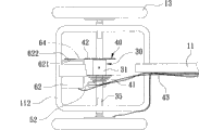
One transmission fluted disc group 40 is please consulted Fig. 4 and shown in Figure 5 simultaneously, is respectively lateral plan and the top view of the utility model three-wheel vehicle first embodiment; This transmission fluted disc group 40 is connected on this differential gear 30, and this transmission fluted disc group 40 includes one first transmission fluted disc 41 and one second transmission fluted disc 42, this is first years old, the second transmission fluted disc 41,42 are connected with group with this transmission pedestal 31 respectively, and axle sleeve is on described transmission shaft 35 respectively, simultaneously, this first transmission fluted disc 41 first drives 21 of fluted discs and is connected by one first Transmission 43 with this, this first transmission fluted disc 41 is a Variable speed fluted disc in the utility model embodiment, this second transmission fluted disc 42 is a single speed fluted disc, and this first Transmission 43 is a chain, in addition, in this first transmission fluted disc 41 and this first driving fluted disc 21, at least one is the fluted disc of unidirectional start, and this first transmission fluted disc 41 is the fluted disc of unidirectional start in the utility model embodiment.
One transmission assembly 50, include a gearshift knob 51 and a Rear Derailleur 52, this gearshift knob 51 is connected on the handlebar 113 of this vehicle frame 11, and this gearshift knob 51 is connected with this Rear Derailleur 52, simultaneously, this Rear Derailleur 52 is connected to this first transmission fluted disc 41 times again, and simultaneously this first is driven fluted disc 21, this first transmission fluted disc 41 and this Rear Derailleur 52 and interconnect with this first Transmission 43, thus, can drive by this gearshift knob 51, and make this Rear Derailleur 52 do a speed change adjustment.
One auxiliary drive unit 60, be connected for 30 groups with this transmission fluted disc, this auxiliary drive unit 60 includes a power unit 61, one motor 62 and a driven unit 63, this power unit 61 is connected to this vehicle frame 11 back segments 112, and this power unit 61 electrically connects mutually with this motor 62, and this motor 62 has extended axially a rotating shaft 621, winding has one second to drive fluted disc 622 in this rotating shaft 621, and this second driving fluted disc 622 is connected with one second Transmission 64 with 42 of this second transmission fluted discs again, simultaneously, this motor 62 also electrically connects mutually with this driven unit 63, and this driven unit 63 can drive this motor 62 starts, in addition, and in this second transmission fluted disc 42 and this second driving fluted disc 622, at least one is the fluted disc of unidirectional start, these second biography, 622 active toothed disks are the fluted disc of unidirectional start in the utility model embodiment, and simultaneously, this power unit 61 is a battery, this driven unit 63 is for driving handle, and this second Transmission 64 is a chain.
By for further understanding the effect that the utility model structural attitude, application technology means and institute's expection are reached, now the utility model occupation mode is narrated, believing be able to have more deep and concrete understanding to the utility model therefrom, as described below:
Still see also Fig. 4 and shown in Figure 5, when implementation and operation the utility model, can trample described stretcher 23 by manpower, and make this first drive fluted disc 21 rotatable starts, simultaneously, this first driving fluted disc 21 also utilizes this first transmission fluted disc 41 of these first Transmission, 43 interlocks, these first transmission fluted disc, 41 further more coaxial rotations drive this transmission pedestal 31, simultaneously, this transmission pedestal 31 can drive described differential umbrella tooth 32 and described driving cog 34 synchronously, and make described driving cog 34 rotations drive described transmission shaft 35, advance and drive described trailing wheel 13 rotations, and when the utility model when turning, described driving cog 34 can be because of the engagement allotment of described differential umbrella tooth 32, and make described driving cog 34 have the effect of differential, in addition, if when the rider has tired out, also can drive this second transmission fluted disc 42 to assist by the motor 62 of this auxiliary drive unit 60, and make this second transmission fluted disc 42 can drive this transmission pedestal 31 synchronously, and reach the effectiveness that drives described trailing wheel 13 starts, in addition, the rider also can drive this transmission pedestal 31 with manpower and motor 62 certainly simultaneously, drive labour-saving effectiveness and reach, in addition, also because of this first, the second transmission fluted disc 41,42 is the fluted disc of unidirectional start, so when this power unit 61 does not have electricity to supply with this motor 62, this motor 62 also can not exert an influence to this differential gear 30, and the rider still can easily drive.
Please consult shown in Figure 6ly more simultaneously, be the combination stereogram of the utility model three-wheel vehicle second embodiment; The utility model second embodiment is all identical with above-mentioned first embodiment substantially, and its main difference be in, this driven unit 63 includes a magnetic strength assembly 631 and a controller 632, and this magnetic strength assembly 631 is located at respectively on this vehicle frame 11 and this first driving fluted disc 21, and this magnetic strength assembly 631 also is connected with this controller 632, simultaneously, this controller 632 electrically connects mutually with this motor 62 again, thus, as rider during in foot-operated described stretcher 23, the described magnetic strength assembly 631 of its rotatable drive, and make described magnetic strength assembly 631 can drive this controller 632 by the variation of magnetic force, and further make this controller 632 these motor 62 starts of control, drive described trailing wheel 13 to drive this differential gear 30, in addition, when foot-operated speed is fast more, this controller 632 also can drive this differential gear 30 by this motor 62 of driven in synchronism at faster speed, the speed that drives with increase.
Claims (8)
1. the three-wheel vehicle configuration that combined type drives is characterized in that, includes:
One transmission car body include a vehicle frame, a front-wheel and two trailing wheels, and this vehicle frame leading portion is pivoted with this front-wheel, and this vehicle frame back segment is then parallel to be pivoted with described trailing wheel;
At least one foot-operated driver element, it is located on this vehicle frame, and should have one first driving fluted disc, two cranks and two stretchers by foot-operated driver element, and this first driving fluted disc is connected with group by described crank and described stretcher;
One differential gear, its binding is arranged between described trailing wheel, and this differential gear includes a transmission pedestal, two differential umbrella teeth, two driving cogs and two transmission shafts, relative winding is provided with described differential umbrella tooth in this transmission pedestal, horizontal opposite side respectively at the described trailing wheel of correspondence in this transmission pedestal is provided with described driving cog, and described differential umbrella tooth and with described driving cog bridle joint mutually, again, described driving cog is connected with described transmission shaft more respectively, and described transmission shaft passes this transmission pedestal, and is connected with group with described trailing wheel;
One transmission fluted disc group, it is connected on this differential gear, and this transmission fluted disc group includes one first transmission fluted disc and one second transmission fluted disc, this first, second transmission fluted disc is connected with group with this transmission pedestal respectively, and the difference axle sleeve is on described transmission shaft, simultaneously, this first transmission fluted disc first drives between fluted disc and is connected by one first Transmission with this, simultaneously, in this first transmission fluted disc and this first driving fluted disc, at least one is the fluted disc of unidirectional start; And,
One auxiliary drive unit, it is connected with this transmission fluted disc group, this auxiliary drive unit includes a power unit, one motor and a driven unit, this power unit electrically connects mutually with this motor, and this motor extended axially a rotating shaft, winding has one second to drive fluted disc in this rotating shaft, and this second drives between fluted disc and this second transmission fluted disc and is connected with one second Transmission, simultaneously, in this second transmission fluted disc and this second driving fluted disc, at least one is the fluted disc of unidirectional start, and this motor also electrically connects mutually with this driven unit, and this driven unit drives this motor start.
2. the three-wheel vehicle configuration that combined type according to claim 1 drives is characterized in that, this driven unit is a driving handle.
3. the three-wheel vehicle configuration that combined type according to claim 1 drives, it is characterized in that, this driven unit includes a magnetic strength assembly and a controller, and this magnetic strength assembly is located at respectively on this vehicle frame and this first driving fluted disc, and this magnetic strength assembly also is connected with this controller, simultaneously, this controller electrically connects mutually with this motor again.
4. the three-wheel vehicle configuration that combined type according to claim 1 drives is characterized in that this power unit is a battery.
5. the three-wheel vehicle configuration that combined type according to claim 1 drives is characterized in that this first transmission fluted disc is a Variable speed fluted disc.
6. the three-wheel vehicle configuration that combined type according to claim 5 drives, it is characterized in that, also include a transmission assembly, this transmission assembly includes a gearshift knob and a Rear Derailleur, this gearshift knob is connected on this vehicle frame, and this gearshift knob is connected with this Rear Derailleur, simultaneously, this Rear Derailleur is connected under this first transmission fluted disc again, and interconnects with this first Transmission.
7. the three-wheel vehicle configuration that combined type according to claim 1 drives is characterized in that this first Transmission is a chain.
8. the three-wheel vehicle configuration that combined type according to claim 1 drives is characterized in that this second Transmission is a chain.
Priority Applications (1)
| Application Number | Priority Date | Filing Date | Title |
|---|---|---|---|
| CN2010201469659U CN201784784U (en) | 2010-03-19 | 2010-03-19 | Compound driven tricycle structure |
Applications Claiming Priority (1)
| Application Number | Priority Date | Filing Date | Title |
|---|---|---|---|
| CN2010201469659U CN201784784U (en) | 2010-03-19 | 2010-03-19 | Compound driven tricycle structure |
Publications (1)
| Publication Number | Publication Date |
|---|---|
| CN201784784U true CN201784784U (en) | 2011-04-06 |
Family
ID=43816760
Family Applications (1)
| Application Number | Title | Priority Date | Filing Date |
|---|---|---|---|
| CN2010201469659U Expired - Fee Related CN201784784U (en) | 2010-03-19 | 2010-03-19 | Compound driven tricycle structure |
Country Status (1)
| Country | Link |
|---|---|
| CN (1) | CN201784784U (en) |
Cited By (2)
| Publication number | Priority date | Publication date | Assignee | Title |
|---|---|---|---|---|
| CN104354826A (en) * | 2013-02-16 | 2015-02-18 | 赵彦杰 | Novel pedal and power-driven convertible car |
| CN106364621A (en) * | 2016-10-13 | 2017-02-01 | 浙江理工大学 | Dual power device for express delivery vehicle |
-
2010
- 2010-03-19 CN CN2010201469659U patent/CN201784784U/en not_active Expired - Fee Related
Cited By (3)
| Publication number | Priority date | Publication date | Assignee | Title |
|---|---|---|---|---|
| CN104354826A (en) * | 2013-02-16 | 2015-02-18 | 赵彦杰 | Novel pedal and power-driven convertible car |
| CN106364621A (en) * | 2016-10-13 | 2017-02-01 | 浙江理工大学 | Dual power device for express delivery vehicle |
| CN106364621B (en) * | 2016-10-13 | 2022-01-25 | 浙江理工大学 | Double-power device of express delivery vehicle |
Similar Documents
| Publication | Publication Date | Title |
|---|---|---|
| JP6694885B2 (en) | Electrically assisted drivetrain system for rickshaw | |
| CN201784784U (en) | Compound driven tricycle structure | |
| CN201890339U (en) | Seat type bicycle with axle transmission | |
| CN203832697U (en) | Transmission mechanism for bicycle free of chain | |
| CN205661619U (en) | Drive mechanism of bicycle and including this drive mechanism's bicycle | |
| JP3169458U (en) | Rowing bicycle | |
| CN201872852U (en) | Portable two-wheeled motor-driven treadwheel | |
| CN201390360Y (en) | Dual drive device of powered vehicle | |
| CN207274872U (en) | One kind is mini to stroll electric car | |
| CN102126533A (en) | Hand-driven large-wheel scooter | |
| CN201721573U (en) | Hand-actuated bull wheel scooter | |
| CN201220731Y (en) | Front wheel double-drive head-controlled rear wheel steering bicycle | |
| CN102001414A (en) | Seat type axle-driven bicycle | |
| CN203864869U (en) | Lying bicycle ridden by two riders corporately | |
| CN203172828U (en) | Wheel set powered by off-axis gravity pressure and bicycle | |
| CN208931569U (en) | The bilateral front driving device of bicycle | |
| CN206766271U (en) | A kind of drive mechanism of Chainless bicycle | |
| CN202213687U (en) | Telescopic crank track type bicycle | |
| CN201023628Y (en) | System speed-variable electric bicycle | |
| CN201999160U (en) | Bicycle | |
| CN205872289U (en) | Bent axle formula direct drive falls tricycle | |
| CN106741547A (en) | It is a kind of to be provided with people's electricity mixed power and the automatic speed-changing wheel disc for exchanging driving of people's electricity | |
| CN201872854U (en) | Portable electric stand-riding bicycle | |
| CN102180223B (en) | Hand and foot driven bicycle | |
| CN202529104U (en) | Galloping bicycle |
Legal Events
| Date | Code | Title | Description |
|---|---|---|---|
| C14 | Grant of patent or utility model | ||
| GR01 | Patent grant | ||
| CF01 | Termination of patent right due to non-payment of annual fee |
Granted publication date: 20110406 Termination date: 20150319 |
|
| EXPY | Termination of patent right or utility model |