CN201754635U - Heavy current line - Google Patents
Heavy current line Download PDFInfo
- Publication number
- CN201754635U CN201754635U CN2010202955029U CN201020295502U CN201754635U CN 201754635 U CN201754635 U CN 201754635U CN 2010202955029 U CN2010202955029 U CN 2010202955029U CN 201020295502 U CN201020295502 U CN 201020295502U CN 201754635 U CN201754635 U CN 201754635U
- Authority
- CN
- China
- Prior art keywords
- water
- cooled cable
- copperhead
- short net
- transformer
- Prior art date
- Legal status (The legal status is an assumption and is not a legal conclusion. Google has not performed a legal analysis and makes no representation as to the accuracy of the status listed.)
- Expired - Fee Related
Links
Images

Landscapes
- Insulated Conductors (AREA)
Abstract
The utility model discloses a heavy current line, comprising a transformer (1), a mobile slip ring (4) and an electrode (5), wherein a water-cooled electric cable fixing rack (2) is arranged on the wall (6), one end of the integrated water-cooled electric cable (3) runs through the water-cooled electric cable fixing rack (2) and is connected with the transformer (1), the other end is connected with the mobile slip ring (4), and the mobile slip ring (4) is connected with the electrode (5) by a copper tube (8). The heavy current line of the utility model can resolve the problem of bad voltage attrition, greatly saves the resource, and brings in huge economic benefit.
Description
Technical field
The utility model relates to a kind of short net, particularly a kind of short net of saving electric energy.
Background technology
The short net of employed furnace of calcium carbide system is equipped with water-cooled compensator, limit phase copper pipe and middle copper pipe mutually in the prior art, the length of short net is long more in actual applications, system impedance is just big more, and it is just many more that secondary voltage descends, thus in the prior art short online waste electric energy very big.The short net system that is provided with water-cooled compensator, limit phase copper pipe and middle copper pipe mutually need use a large amount of joints, and joint is many more, and the electromagnetic interference of generation is strong more, and contact resistance is big more, and system impedance also can increase thereupon, will cause the great wasting of resources like this.
China utility model specification ZL200820237687.0 has announced a kind of short net, improve at deficiency of the prior art, yet this short net only is centering phase copper pipe and the limit improvement of copper pipe shape mutually, make the good heat dissipation of copper pipe, the resistance of the good more copper pipe of copper pipe heat radiation is just more little, the electric energy of waste is just few more, but this structure only is to reduce waste of electric energy, can not solve electric energy fully in short online consumption.
The utility model content
The purpose of this utility model is, a kind of short net is provided.It not only can solve the serious problem of short network loss electric energy, can also save resource greatly, and can bring huge economic benefit.
The technical solution of the utility model: a kind of short net, comprise transformer, mobile collector ring and electrode, body of wall is provided with the water-cooled cable fixed mount, one end of integrated water-cooled cable is connected with transformer through the water-cooled cable fixed mount, the other end is connected with mobile collector ring, and mobile collector ring is connected with electrode by copper pipe.Cancel water-cooled cable compensator, middle phase copper pipe and limit phase copper pipe and directly use integrated water-cooled cable to be connected transformer and mobile collector ring, thoroughly solved the waste of electric energy on water-cooled cable compensator and middle copper pipe mutually and limit phase copper pipe.
In the aforesaid short net, integrated water-cooled cable comprises locking nut, binding ring, copperhead one and copperhead two, one end of integrated water-cooled cable is provided with copperhead one, copperhead one inside is provided with 2 sealing rings, the outside is provided with binding ring and locking nut, and copperhead one is fixed on the transformer by binding ring and locking nut; The other end of integrated water-cooled cable is provided with copperhead two, and copperhead two is welded on the mobile collector ring.Carry out position compensation by transformation with regard to not needing the using compensation device, reduced a lot of joints like this, contact resistance is reduced water-cooled cable two end connectors.
In the aforesaid short net, integrated water-cooled cable surface is provided with rubber tube, and the two ends of rubber tube are provided with the stainless steel cassette tape.Rubber tube is set in order to protect integrated water-cooled cable.
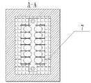
In the aforesaid short net, in the body of wall around the water-cooled cable fixed mount, be provided with bamboo reinforcement.With bamboo reinforcement replace bar construction of the prior art effectively prevented water-cooled around produce magnetic field.
Compared with prior art, the utility model has been cancelled middle phase copper pipe, limit phase copper pipe and compensator and has been replaced by integrated water-cooled cable, has thoroughly solved the loss of electric energy on middle phase copper pipe, limit phase copper pipe and compensator.The joint quantity that adopted structure decrease of the present utility model has not only reduced contact resistance and system impedance, and has made current density even.Add resistant to elevated temperatures insulating coating, rational queueing discipline has reduced and has reduced the kelvin effect and the self neutralizing frequency coefficient of short net system, greatly reduces the loss of electric power.Owing to adopt the entire body water-cooled cable to make the compact more and optimization of short net system configuration, saved a large amount of nonferrous materials copper pipe and manufacturing cost thereof, also saved a large amount of stainless steels simultaneously and hung, saved a large amount of resources.
Research according to the inventor has drawn following results:
By discovering one meter of the every increase of short net, secondary voltage decline 0.5V then:
ΔV=(11.6-5.7)·0.5=2.95V
With the 25000KVA furnace of calcium carbide is that example is calculated, and will reduce voltage decline loss:
V2=187V I2=77188A pressure reduction △ V=2.95V
P is former=I2V2 √ 3=25000KVA
P shows=I2 (V2-△ V) √ 3=24605KVA
Power loss P=P is former-and P is existing=395KVA
Per hour lose electric energy=395kw/h
Lose electric energy=395kw/h24=9360kw/h every day
Annual 300 days to be electric energy=9360kw/h300 days=2808000kw/h of benchmark counting loss economic loss 2808000kw/h0.40 unit=112.32 ten thousand yuan
But calculate 33000KVA electric furnace energy savings by above formula
395kw/h ÷ 25000KVA33000KVA=is saves energy 521.4kw/h saves energy=521.4kw/h24=12513.6kw/h every day per hour
Annual was benchmark calculated savings electric energy=3754080kw/h with 300 days
Economic benefit 3754080kw/h0.40 unit=150.16 ten thousand yuan
By top data as can be seen, adopt structure of the present utility model not only to save resource but also saved a large amount of electric energy, and brought huge economic benefit.
Description of drawings
Fig. 1 is a structural representation of the present utility model;
Fig. 2 is the structural representation of bamboo reinforcement;
Fig. 3 is the structural representation of integrated water-cooled cable.
Being labeled as in the accompanying drawing: the 1-transformer, 2-water-cooled cable fixed mount, the integrated water-cooled cable of 3-, 4-moves collector ring, the 5-electrode, the 6-body of wall, 7-bamboo reinforcement, 8-copper pipe, 9-locking nut, 10-binding ring, the 11-sealing ring, 12-copperhead one, 13-rubber tube, 14-stainless steel cassette tape, 15-copperhead two.
Embodiment
Below in conjunction with drawings and Examples the utility model is further described.
Embodiment of the present utility model: short net, comprise transformer 1, mobile collector ring 4 and electrode 5, body of wall 6 is provided with water-cooled cable fixed mount 2, one end of integrated water-cooled cable 3 is connected with transformer 1 through water-cooled cable fixed mount 2, the other end is connected with mobile collector ring 4, and mobile collector ring 4 is connected with electrode 5 by copper pipe 8.Integrated water-cooled cable 3 comprises locking nut 9, binding ring 10, copperhead 1 and copperhead 2 15, one end of integrated water-cooled cable 3 is provided with copperhead 1, copperhead one 12 inside are provided with sealing ring 11, the outside is provided with binding ring 10 and locking nut 9, and copperhead 1 inserts transformer 1, adopts 11 sealings of two seals circle, compress by 9 pairs of copperheads 1 of stainless steel nut and to finish connection, this connected mode contact-making surface conducts electricity very well greatly, and the cooling water sealing property is strong, and Installation and Debugging are easy; The other end of integrated water-cooled cable 3 is provided with copperhead 2 15, and copperhead 2 15 welds together with after mobile collector ring 4 is connected by bolt, novel connection way makes each contact of short net good, cleaning, non-oxidation, difficult loosening, its contact resistance is little, the effective rate of utilization height of electric energy.Integrated water-cooled cable 3 surfaces are provided with rubber tube 13, and the two ends of rubber tube 13 are provided with stainless steel cassette tape 14.Be provided with bamboo reinforcement 7 in the body of wall 6 around water-cooled cable fixed mount 2.
Claims (4)
1. one kind short net, comprise transformer (1), mobile collector ring (4) and electrode (5), it is characterized in that: body of wall (6) is provided with water-cooled cable fixed mount (2), one end of integrated water-cooled cable (3) is connected with transformer (1) through water-cooled cable fixed mount (2), the other end is connected with mobile collector ring (4), and mobile collector ring (4) is connected with electrode (5) by copper pipe (8).
2. short net according to claim 1, it is characterized in that: integrated water-cooled cable (3) comprises locking nut (9), binding ring (10), copperhead one (12) and copperhead two (15), one end of integrated water-cooled cable (3) is provided with copperhead one (12), copperhead one (12) inside is provided with 2 sealing rings (11), the outside is provided with binding ring (10) and locking nut (9), and copperhead one (12) is fixed on the transformer (1) by binding ring (10) and locking nut (9); The other end of integrated water-cooled cable (3) is provided with copperhead two (15), and copperhead two (15) is welded on the mobile collector ring (4).
3. short net according to claim 1 and 2 is characterized in that: integrated water-cooled cable (3) surface is provided with rubber tube (13), and the two ends of rubber tube (13) are provided with stainless steel cassette tape (14).
4. short net according to claim 1 is characterized in that: be provided with bamboo reinforcement (7) in water-cooled cable fixed mount (2) body of wall (6) all around.
Priority Applications (1)
| Application Number | Priority Date | Filing Date | Title |
|---|---|---|---|
| CN2010202955029U CN201754635U (en) | 2010-08-18 | 2010-08-18 | Heavy current line |
Applications Claiming Priority (1)
| Application Number | Priority Date | Filing Date | Title |
|---|---|---|---|
| CN2010202955029U CN201754635U (en) | 2010-08-18 | 2010-08-18 | Heavy current line |
Publications (1)
| Publication Number | Publication Date |
|---|---|
| CN201754635U true CN201754635U (en) | 2011-03-02 |
Family
ID=43622366
Family Applications (1)
| Application Number | Title | Priority Date | Filing Date |
|---|---|---|---|
| CN2010202955029U Expired - Fee Related CN201754635U (en) | 2010-08-18 | 2010-08-18 | Heavy current line |
Country Status (1)
| Country | Link |
|---|---|
| CN (1) | CN201754635U (en) |
-
2010
- 2010-08-18 CN CN2010202955029U patent/CN201754635U/en not_active Expired - Fee Related
Similar Documents
| Publication | Publication Date | Title |
|---|---|---|
| CN204407893U (en) | For the harmonic reactive compensating apparatus of Standard type | |
| CN111768939A (en) | A basin-type insulator casting and assembly for large-capacity transmission lines | |
| CN104037717A (en) | Middle joint connection tube of phase-change temperature-control type high-voltage cable | |
| CN201754635U (en) | Heavy current line | |
| CN203103534U (en) | Connection wire clamp between casing pipe lead wire screw rod and circuit guide wire of power distribution transformer | |
| CN109243728B (en) | Direct current gas insulated metal enclosed transmission line insulator | |
| CN203983937U (en) | Phase-change temperature control formula high-voltage cable middle joint tube connector | |
| CN211624558U (en) | Novel wax control paraffin removal flexible composite pipe for oil field | |
| CN210860245U (en) | High-efficiency heat tracing pipe | |
| CN202094580U (en) | Novel jumping suspension clamp for squirrelcage jumping end part | |
| CN202633874U (en) | Ice melting system capable of switching alternating current and direct current | |
| CN212648978U (en) | Protection architecture of copper aluminium interface alloy line among power transmission and distribution equipment | |
| CN202190076U (en) | Comprehensive electricity saver | |
| CN206472046U (en) | A kind of split type high-frequency inversion dc source applied to foil machine | |
| CN215479750U (en) | Lithium battery negative electrode material graphitization purification device | |
| CN201985269U (en) | Pre-tightening tubular insulation bus joint | |
| CN208489369U (en) | Earthing device of electrical equipment | |
| CN106786709A (en) | A kind of flexible direct current converter station main electrical scheme Optimal Configuration Method | |
| CN206401156U (en) | A high-voltage dry-type air-core series reactor based on linearity control | |
| CN217441953U (en) | Oil well produced liquid temperature control heating system utilizing solar energy for preheating | |
| CN202067909U (en) | Small-bus connecting structure for switch cabinet | |
| CN206806238U (en) | A kind of disk welding bellows of service life length | |
| CN202434286U (en) | Connection separator for fence framework of dry-type air-core reactor | |
| CN202834577U (en) | Improved pipeline for oil exploitation | |
| CN215856431U (en) | Electrolyzer busbar heating improvement device |
Legal Events
| Date | Code | Title | Description |
|---|---|---|---|
| C14 | Grant of patent or utility model | ||
| GR01 | Patent grant | ||
| CF01 | Termination of patent right due to non-payment of annual fee |
Granted publication date: 20110302 Termination date: 20160818 |
|
| CF01 | Termination of patent right due to non-payment of annual fee |