Background technology
The building energy data book of announcing according to USDOE in 2006 claim, the american energy consumption has 38.6% (wherein 21.1% to consume from the resident from resident and commercial building, 17.4% from commerce), secondly be industrial consumption 33% and transportation consumption 28% (seeing book 1.13).Claim in the book that American Architecture has used 71% electric power now, accounts for 79% of total electricity consumption.Building has also consumed 55% of total natural gas, accounts for 62% (seeing book 1.16,1.17) of natural gas total flow.In the building energy total amount consumed, the space heating, space refrigeration, the water heating, 54% (commerce accounts for 42%, and the resident accounts for 63%) that ventilation and refrigeration facility account for total consumption, above-mentioned these account for 54% (data summarization form 7) of total use consumption.Therefore, American Architecture accounts for 38% of U.S.'s carbon discharge capacity, and global average is 9.8% (book 3.1.2), and emission of carbon-dioxide is one of reason that causes global warming.If add resident, commercial and industrial facility building, above-mentioned all data will be higher.
In general, the HVAC in resident and the commercial building (heating, heating ventilation and air-conditioning system), refrigerator, the system of hot water and swimming pool/message bathtub heating is independent operating.Such as in the typical building, air-conditioning and furnace are used for refrigeration and heat, and natural gas heating or electrical heating are used for hot-water heating system, and natural gas heating or heat pump are used for pond/Saunas heating, and the refrigerator refrigeration is used for F﹠B and stores.The total thermal efficiency of above-mentioned system is very low, and reason is to lack between the different system cooperation.In the season of needs refrigeration, we still need heating to obtain hot water.In winter, refrigerator still needs refrigeration.Sometimes, also can produce negative effect in opposition to each other each other between the system.Surpassed the heat that it is taken away in the refrigerator such as, the heat that the operation of refrigerator produces, the heat of its generation increased the load of refrigeration to room air conditioner.The HVAC system of most of residents and commercial building is subregion control, and the obsolete room in zone also can be because of other rooms need reduce or the rising temperature, thereby make the cost increase.
Before this, there has been the researcher to attempt to freeze and heat-production functions is joined together, such as heating of air-conditioning and pond or water heater funnel are joined together limitedly.
United States Patent (USP) 5495723, date of publication is on March 5th, 1996, inventor Kenneth MacDonald has delivered a kind of air-conditioning system, it is to add a water cooling heat exchanger in general air source air-conditioning system, air cooling all is connected by a triple valve with water cooling heat exchanger, if system is the water heating mode, also have two check-valves.The problem of this kind method first is that after indoor temperature was reduced to perfect condition, although need the water heating, at this moment the water heating function was invalid, will quit work.Second problem is one of them refrigerant of not participated in circulation in the heat exchanger of bypass, under different operating modes and initial start up conditions, all have different, thereby may cause compressor oil to reflux and different running environment under system's refrigerant filling amount have big fluctuation.When too much filling amount is limited in by the heat exchanger of bypass, thereby the operation filling amount may be crossed and lowly can not reach optimum Working, and with the compressor lubricant oil that is mixed of refrigerant also because some can not get back to compressor, thereby may make compressor can not obtain effectively lubricating.Under some other situation, during by heat exchanger place few of refrigerant of bypass, the refrigerant filling amount will be too many during the system operation, from causing occurring back in the compressor suction phenomenon of liquid.This system also is confined to indoor refrigerating function and water heating function.
The U.S. Patent number that on October 1st, 1996 announced is 5560216, and the invention people is RobertL.Holmes, discloses the patent of said function as above, and difference is that it has used two magnetic valves and two check-valves to realize bypass functionality.Equally, this patent exists the shortcoming of above-mentioned patent.Also be only to be confined to indoor refrigeration and water heating function.
The U.S. Patent number that on May 25th, 1999 announced is 5906104, and the invention people is Jay H.Schwartz etc., discloses the function same as the patent of MacDonald.Except having increased some accessories, such as oil eliminator, heat exchanger between compressor air suction mouth and the condensator outlet and fluid reservoir etc.Schwartz also has been to use a triple valve and two check-valves that a water source heat exchanger and a heat pump are combined.Water can not be heated when the heating mode of space.Identical with the MacDonald patent, when the air conditioning pattern, also there is identical bypass defective in this patent.
The patent No. of announcing on December 16th, 1975 is that 3926008 invention people introduce a water-cooling system for Robert C.Webber, and is identical with above-mentioned patent bypass reason, is directly used in swimming pool, air regulator.Therefore exist identical defective.But this patent adds an air source evaporimeter with same bypass thinking solves the problem that the water heating function lost efficacy when indoor temperature reduces.The bypass problem that the appearance of two bypass heat exchangers makes above-mentioned other patents face is more outstanding.
The patent No. of announcing on November 11st, 1980 is that 4232529 invention people are FrederickJ.Babbitt etc., has introduced the heat pump of a kind of water source heat exchanger. this system has used three check-valves and a triple valve to realize cooling agent bypass flow function between water source heat exchanger and air source heat exchanger.It is confined to indoor temperature cold conversion of heat and water heating.The defective that in like manner has above-mentioned patent.
U.S. Patent number 2007/0028634 has been announced the method that swimming pool heat pump and building air-conditioning are combined.The cold air of swimming pool evaporator with heat pump cooling provides than the better low-temperature receiver of surrounding environment, and the hot gas of air-conditioning generation simultaneously provides better thermal source for the pond heat pump.A defective of this method is to control the plenum chamber of air-flow within doors and pressure head that current divider box causes fan system increases.After air-conditioner temperature was reduced to setting value, because the fan pressure head increases, fan rotor load increased, and the swimming pool heat pump can not obtain more thermal source, was that the fan motor power consumption increases on the contrary.Otherwise it is the same.
Daikin enterprise and some other companies for resident's architectural design a heat pump without the air channel cold and hot adjusting is provided.It has an off-premises station and several at the indoor fan coil pipe of chummery not.The indoor fan coil pipe be arranged in parallel in the refrigerant loop, independent control.Idle indoor fan coil pipe is then by the magnetic valve bypass.Such system can be only provides cold and hot to required refrigeration or the room that heats.It needs frequency-changeable compressor to adjust complete machine output cold or heat usually.But it is too much that such system is not suitable for the room.In such system, need couple together with copper refrigeration piping and off-premises station.Pipeline is longer, and the pressure loss is higher, so the filling amount of refrigerant is bigger, and the possibility of coolant leakage is just than general height.Add that copper material is expensive, the whole system cost improves.Same because the refrigerant of the participation circulation that bypass is brought is different under different operating conditions, be difficult to control.
Summary of the invention
The purpose of this utility model is to solve the problems of the technologies described above, a kind of integrated heat exchange system is provided, can be reliably the cold and hot system in the integrated building effectively, provide high energy efficiency space refrigeration, heat, the refrigerating and heating systems of the relevant demand of freeze and heat of water heating with other, thereby make each function with each subsystem independence or finish the work simultaneously.
For this reason, the technical solution adopted in the utility model is such:
Integrated heat exchange system comprises compressor, heat exchanger, expansion valve, is connected to each other by pipeline and forms the loop, and refrigerant circulates in the loop, it is characterized in that:
A) comprise at least three heat exchangers in the system;
B) comprise one group of changeable valve combination in the system, be used for controlling the flow direction of refrigerant in the loop, this changeable valve combination comprises at least four ports, wherein hold for flowing into along the valve combination inlet of the nearest flow process of refrigerant flow direction from exhaust outlet of compressor, be outflow end from the compressor air suction mouth against the valve combination of the nearest flow process of refrigerant flow direction inlet, all the other ports are the shunting end, link to each other with pipeline between each shunting end; Outflow end and flow between the end and be the external circuit through the pipeline of compressor flows between end and the outflow end and is home loop without the pipeline of overcompression machine; Refrigerant through the external circuit, enters home loop from flowing into end behind compressor, leave home loop from outflow end again, gets back to compressor through the external circuit again;
C) in the described heat exchanger, at least one is positioned on the home loop;
D) compressor, all heat exchangers and expansion valve are on the mobile loop of refrigerant all the time, and the cold medium flux of above-mentioned each parts of flowing through is identical.
Described changeable valve combination can have the mode of multiple realization, as adopts independent power on/off magnet valve, then should comprise four independent power on/off magnet valves doing quadrangular array at least; Also can directly adopt a solenoid operated four-way valve to realize; Or adopt two three-way solenoid valves; And the combination of a three-way solenoid valve and two independent power on/off magnet valves.Need to prove that above-mentioned implementation is for guaranteeing four ports are arranged, and finishes the required minimum quantity of goal of the invention, can adopt also that more valve sets is incompatible to obtain same or better effect.
Above-mentioned C group technical characterictic, two kinds of forms more specifically can be arranged, the first: in the described heat exchanger, at least one is positioned on the home loop, and at least one is positioned on the external circuit; It two is: comprise at least that in changeable valve combination under the situation of eight ports, described heat exchanger also can all be positioned on the home loop.
Further, described compressor, all heat exchangers and expansion valve are being disregarded under the situation of valve leak being in all the time under any operational mode on the mobile loop of refrigerant, and the cold medium flux of the above-mentioned parts of flowing through is identical under all operational modes.
One or more thermal storage devices that have in described each heat exchanger.
Described system can realize independent cooling, heats, simultaneously the function of cooling and warming.
As better technical scheme, this system also comprises a control device based on microprocessor, be provided with many places temperature and/or pressure sensor in the system, after microprocessor is received each temperature and/or pressure signal, according to work such as predefined pattern control compressor, solenoid operated four-way valve, heat exchangers.
The utility model is mainly finished with " changeable valve combination " the control in loop, and this is a notion that the utility model proposes.Commercial already solenoid operated four-way valve has another name called four-way change-over valve, is exactly a kind of typical changeable valve combination, it has four abcd ports, by the path conducting of signal of telecommunication control abdc or adbc, and can switch between dual mode, concrete visible embodiment partly describes.In this case, a, c become inflow end and outflow end, and b, d can be described as the shunting end, link to each other with pipeline between bd, and the formation home loop, this is basic, the simplest implementation.
As not adopting ready-made solenoid operated four-way valve, also can with four independently the power on/off magnet valve do quadrangular array, thereby realize the switching of conduction mode by each valve of signal of telecommunication Synchronization Control, this mode is actually disintegrates ready-made solenoid operated four-way valve, be distributed to everywhere, same function also can by triple valve or triple valve and independently the power on/off magnet valve form jointly.
The utility model has also proposed the notion of home loop and external circuit, and from preamble as seen, the inventor regards the pipeline in changeable valve combination and the control range thereof as an integral body, is called home loop; Remainder is called the external circuit.
Only be made up of four magnetic valves or a four way solenoid valve in changeable valve combination, promptly only have under the situation of four ports, it only has two shuntings to hold the pipeline between reaching to constitute simple relatively home loop; Under the situation of changeable valve combination more complicated, because the shunting end increases, mutual pipeline also increases, and home loop can be comparatively complicated.
As can be known aforementioned, externally on the loop, the flow direction of refrigerant is fixed, promptly from exhaust outlet of compressor to flowing into end, from outflow end to the compressor air suction mouth.As a heat exchanger being placed the compressor bleed air mouth to flowing between the end, then this heat exchanger must be the heat release heat exchanger in the thermodynamic cycle, plays exothermic effects; As a heat exchanger being placed outflow end between the compressor air suction mouth, then this heat exchanger must be the heat absorption heat exchanger in the thermodynamic cycle, plays heat-absorbing action; As respectively placing a heat exchanger at above-mentioned two places, then these two heat exchangers must be respectively heat release heat exchanger and heat absorption heat exchanger, play different effects.As seen, externally on the loop, the heat exchanger role is fixed, by its residing determining positions.
And on home loop, the flow direction of refrigerant can be unfixed, can just reverse switching.On the home loop as a heat exchanger is placed, then this heat exchanger role depends on the switch mode of magnetic valve, and the upstream and downstream of the flow direction of the refrigerant that brings thus and this heat exchanger and expansion valve relation, make it between heat absorption and heat release, switch.
Enough complicated in changeable valve combination, have at least under the situation of eight ports, by rational circuit design, can make at least one pipeline in its home loop have fixing flow direction all the time, no matter and how magnetic valve switches.In the case, even all heat exchangers are all placed home loop, also can there be one or more heat exchangers to play fixing heat release or heat-absorbing action.
As seen, in the system of the present utility model, the effect of part heat exchanger in heat exchange systems fixed, another part then is variable, if system has fixed exothermic effects for one and has been used for heating with three heat exchangers, fixed heat-absorbing action for one and be used for freezing, cooling and heating load all less than situation about satisfying under, can freeze simultaneously and heat; Under the situation about in refrigeration duty, being satisfied, corresponding heat absorption heat exchanger water circulating pump or blower fan are out of service, the switchable heat exchanger of another one can switch to the heat absorption operational mode and replace fixing endothermic heat exchanger, allow the heat exchanger of fixedly heat release continue heat production, thereby the function that realization heats separately is till thermic load satisfies; Under the situation about in thermic load, being satisfied, corresponding heat release heat exchanger water circulating pump or blower fan are out of service, the switchable heat exchanger of another one can switch to the heat release operational mode and replace fixing heat release heat exchanger, allow the heat exchanger of fixing heat absorption continue heat absorption, thereby realize the function of separate refrigeration, till refrigeration duty satisfies.The pattern of freezing simultaneously and heating is actual to be with the first in addition balance of the cooling and heating load demand in the building, and independent refrigeration or heating mode are exactly that part to the difference of wherein loading compensates.
This design of the present utility model, no matter how the pattern of changeable valve combination changes, flowing of the refrigerant in the system is mobile successively all the time, do not have the loop of shunting and bypass, cold-producing medium 100% ground circulates in pipeline, does not have the problem of bypass, branch.
Use the control device of being with microprocessor to control the operation of whole system, can set plurality of operating modes easily, and make system between these patterns, switch, better integrated effect is provided.
The specific embodiment
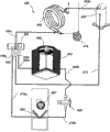
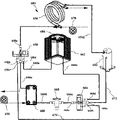
Referring to Fig. 1.Conventional heat-exchange system 10 comprises that a compressor 26 is the acting input equipment; Two heat exchangers, i.e. freezing machine 14 and rapid steamer 22, freezing machine 14 is as the heat absorption heat exchangers, and rapid steamer 22 is as the heat release heat exchanger; An expansion valve 18 plays a part to exert pressure and control fluid; Said modules is connected to become refrigerating circuit by pipeline 12,16,20 and 24.Refrigerant circulates in the loop, thereby finishes the thermal procession of steam compression cycle.
When 10 work, refrigerant continuous-flow, successively by compressor 26, pipeline 12, freezing machine 14, pipeline 16, expansion valve 18, pipeline 20, rapid steamer 22, pipeline 24 is got back to compressor 26 then and is finished whole circulation.Heat is dissipated to second kind of heat transfer medium by freezing machine 14, such as air or water, and from second kind of heat transfer medium, absorb heat such as air or water after, absorb in the system by rapid steamer 22.
Referring to Fig. 2.Solenoid operated four-way valve 50 comprises a pilot valve 34 and a main valve 44.Pilot valve 34 is subjected to the control of solenoid 36, and main valve is followed pilot valve 34 action by the tubule 46,48,38 and 40 between pilot valve 34 and the main valve 44.It comprises four ports 42,28,30,32, when solenoid 36 energisings, port 42 (below deserve to be called port) and port 28 (to call left port in the following text) conducting, port 30 (to call middle port in the following text) and port 32 (to call right output port in the following text) conducting, and these two flow channels are independent of each other; When the power supply supply of solenoid 36 is cut off, port 42 and port 32 conductings, port 30 and port 28 conductings, and these two flow channels are independent of each other.
Below among each embodiment of the present utility model, the drawing reference numeral of identical parts in different embodiment is basic identical, promptly the first numeral might change, but several bit digital in back remain unchanged.As in different accompanying drawings, 162,262,362,462 etc. all represent an air-cooled heat exchanger; 158,258,358,458 etc. all represent a changeable valve combination.Do not point out in explanatory note that as a certain drawing reference numeral rule is referring to the description of other embodiment in view of the above.
Embodiment one
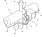
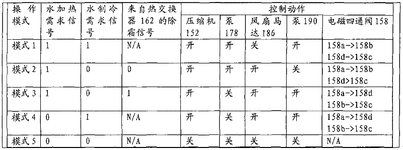
Referring to Fig. 3, Fig. 4, present embodiment is the most basic embodiment of the utility model.Heat-exchange system 180 comprises 156,162,188, one expansion valves 168 of 152, three heat exchangers of a compressor and a solenoid operated four-way valve 158, and wherein solenoid operated four-way valve 158 has four port abcd, all is linked as the loop by pipeline with upper-part.Concrete loop is as follows: the exhaust outlet of compressor 152 links to each other with heat exchanger 156 by pipeline 154a; Heat exchanger 156 further links to each other with the upper port 158a of solenoid operated four-way valve 158; The left port 158b of solenoid operated four-way valve 158 successively links to each other with expansion valve 168, heat exchanger 162, right output port 158d by pipeline 170,160b, 160a; The lower port 158c of solenoid operated four-way valve 158 links to each other with heat exchanger 188 by pipeline 172a, thereby and links to each other with the air entry of compressor 152 by pipeline 172b and to finish circulation.By above description as can be known, the changeable valve combination of present embodiment is a solenoid operated four-way valve 158, and its upper port 158a is for flowing into end, and lower port 158c is an outflow end, and with compressor 152, heat exchanger 156,188 is formed the external circuit; Port one 58b, 158d are the shunting end, form home loop with expansion valve 168, heat exchanger 162.
During the present embodiment operation, refrigerant is from compressor 152, the heat exchanger 156 of flowing through, enter home loop from 158a, two kinds of selections are arranged in home loop, the path is respectively 158a-158b-168-162-158d-158c, or 158a-158d-162-168-158b-158c, get back to the external circuit from 158c then, get back to compressor 152 behind the heat exchanger 188 of flowing through, finish circulation.In this running, heat exchanger 156 is always the heat release heat exchanger, and 188 are always the heat absorption heat exchanger, and their effect is constant; Heat exchanger 162 can become the heat release heat exchanger according to different Path selection, also can become the heat absorption heat exchanger.So present embodiment can switch between these two kinds of patterns.
Heat exchanger 156 has a boiler (not shown) as thermal storage device, and heat exchanger 188 has a cold water storage cistern (not shown) as thermal storage device.Pump 178 is made the water circulation opposite with the refrigerant flow direction between heat exchanger 156 and its boiler; Pump 190 is made the water circulation opposite with the refrigerant flow direction between heat exchanger 188 and its cold water storage cistern.Heat exchanger 162 circulates by air-flow by fan motor 186.
In addition, the heat exchanger 162 in the present embodiment also can be placed on the pipeline 170.
Present embodiment is controlled its operation by one based on the control device of microprocessor, and microprocessor is to the refrigeration demand signal from cold water storage cistern, boiler heat desired signal, the defrosting signal of heat exchanger 162 feeds back.Two thermostats are arranged on boiler and the enterprising trip temperature control of cold water storage cistern.Temperature sensor is arranged on and sends the defrosting signal on the heat exchanger 162.Present embodiment also is provided with as refrigerant high-voltage switch gear, high-temperature-hot-water switch, anti-freeze temperature switch, safety switches such as water flow velocity switch.Because it is above freezing that cold water temperature is arranged on, after cold water storage cistern sent the refrigeration demand signal, control system was not reacted the defrosting signal that heat exchanger 162 sends.Table 1 listed present embodiment the various patterns that may occur.
Table 1
1 expression " having " in the table, 0 expression " nothing ", N/A is illustrated in and does not consider this signal in this pattern.
When heating when occurring simultaneously with refrigeration demand, device is by pattern 1 operation.Hot water and cold water are supplied simultaneously.When having only refrigeration demand, at this moment system only goes out cold water according to pattern 4 operations.
When only heating demand, system adopts different mode work according to the defrosting demand.If do not defrost demand, system running pattern 2, when the defrosting demand of automatic heat-exchanger 162 occurring coming, system running pattern is transformed into mode 3, and in mode 3, system utilizes defrost cycle further the cold water storage cistern temperature to be reduced under the setting value.The water temperature of coming out when heat exchanger is during near freezing point, and the freezing point temperature switch will cut off system.Take place under this situation situation that environment temperature is extremely low around.In the case, any heat pump operating efficiency descends, and will need auxiliary firing equipment to carry out the indoor heating demand.
Embodiment two
Referring to Fig. 5.Present embodiment is the analogue of embodiment one, and this heat-exchange system comprises 156,162,188, one expansion valves 168 of 152, three heat exchangers of a compressor and a changeable valve combination 158 equally, and line arrangement is also identical with embodiment one.Difference is, the changeable valve combination of present embodiment is to make four independent power on/off magnet valve 158A, 158B, 158C, the 158D of quadrangular array, between per two adjacent valves, form a port, be respectively 158a, 158b, 158c, 158d, wherein 158a is for flowing into end, 158c is an outflow end, and port one 58b, 158d are the shunting end.Other the method for operation, control mode are all in full accord with embodiment one, repeat no more.
Embodiment three
Referring to Fig. 6.Present embodiment also is the analogue of embodiment one, and this heat-exchange system comprises 156,162,188, one expansion valves 168 of 152, three heat exchangers of a compressor and a changeable valve combination 158 equally, and line arrangement is also identical with embodiment one.Difference is that the changeable valve combination of present embodiment is made up of two three- way solenoid valve 158E, 158F, forms four port one 58a, 158b, 158c, 158d, and wherein 158a is for flowing into end, and 158c is an outflow end, and port one 58b, 158d are the shunting end.Other the method for operation, control mode are all in full accord with embodiment one, repeat no more.
Embodiment four
Referring to Fig. 7.Present embodiment also is the analogue of embodiment one, and this heat-exchange system comprises 156,162,188, one expansion valves 168 of 152, three heat exchangers of a compressor and a changeable valve combination 158 equally, and line arrangement is also identical with embodiment one.Difference is, the changeable valve combination of present embodiment is made up of a three-way solenoid valve 158E and two independent power on/off magnet valve 158B, 158C, forms four port one 58a, 158b, 158c, 158d, and wherein 158a is for flowing into end, 158c is an outflow end, and port one 58b, 158d are the shunting end.Other the method for operation, control mode are all in full accord with embodiment one, repeat no more.
Embodiment five
Referring to Fig. 8, Fig. 9.Present embodiment has the basic framework similar to embodiment one, and wherein Reference numeral is also corresponding to the mark of Fig. 3, Fig. 4, just unifiedly changes the first place into 2.The heat-exchange system 280 of present embodiment comprises a compressor 252, four heat exchangers 256,262,285,288, an expansion valve 268 and a solenoid operated four-way valve 258, wherein solenoid operated four-way valve 258 has four port abcd, all is linked as the loop by pipeline with upper-part.The difference of present embodiment and embodiment one is to have increased a heat exchanger 285, and home loop is made up of shunting end 258b, 258d, heat exchanger 262,285, expansion valve 268.During operation, heat exchanger 262,285 1 is the heat absorption heat exchanger, and another is the heat release heat exchanger, and can switch mutually.
Heat exchanger 256 has a boiler (not shown) as thermal storage device, and heat exchanger 288 has a cold water storage cistern (not shown) as thermal storage device.Pump 278 is made the water circulation opposite with the refrigerant flow direction between heat exchanger 256 and its boiler; Pump 290 is made the water circulation opposite with the refrigerant flow direction between heat exchanger 288 and its cold water storage cistern.Heat exchanger 262 circulates by air-flow by fan motor 286; Heat exchanger 285 circulates by air-flow by fan motor 287.
By microprocessor control, control model sees Table 2 to present embodiment equally.
Table 2
1 expression " having " in the table, 0 expression " nothing ", N/A is illustrated in and does not consider this signal in this pattern.
Embodiment six
Referring to Figure 10.The heat-exchange system 380 of present embodiment comprises a compressor 352, three heat exchangers 362,356,385, an expansion valve 368 and a solenoid operated four-way valve 358, wherein solenoid operated four-way valve 358 has four port abcd, all is linked as the loop by pipeline with upper-part.Concrete loop is as follows: the exhaust outlet of compressor 352 links to each other with heat exchanger 362 by pipeline 354a; Heat exchanger 362 further links to each other with the upper port 358a of solenoid operated four-way valve 358; The left port 358b of solenoid operated four-way valve 358 successively links to each other with heat exchanger 385, expansion valve 368, heat exchanger 356, right output port 358d by pipeline 370a, 370b, 360b, 360a; Thereby the lower port 358c of solenoid operated four-way valve 358 links to each other with the air entry of compressor 352 by pipeline 372 and finishes circulation.By above description as can be known, the changeable valve combination of present embodiment is a solenoid operated four-way valve 358, and its upper port 358a is for flowing into end, and lower port 358c is an outflow end, and with compressor 352, heat exchanger 362 is formed the external circuit; Port 358b, 358d are the shunting end, form home loop with expansion valve 368, heat exchanger 356,385.That is, present embodiment has a heat exchanger externally on the loop, and has two heat exchangers to be on the home loop.
During the present embodiment operation, refrigerant is from compressor 352, the heat exchanger 362 of flowing through, enter home loop from 358a, two kinds of selections are arranged in home loop, the path is respectively 358a-358b-385-368-356-358d-358c, or 358a-358d-356-368-385-358b-358c, get back to the external circuit from 358c then, and get back to compressor 352, finish circulation.In this running, heat exchanger 362 is always the heat release heat exchanger, and its effect is constant; Heat exchanger 356 can become the heat release heat exchanger with 385 according to different Path selection, also can become the heat absorption heat exchanger.So present embodiment can switch between these two kinds of patterns.
Wherein, heat exchanger 362 and 385 is air-cooled, circulates by air-flow by fan motor 386 and 387; 356 is water-cooled, and pump 378 is made the water circulation opposite with the refrigerant flow direction between heat exchanger 356 and its boiler.
Have only a water source heat exchanger 356 in this example, receive cold water storage cistern and boiler simultaneously by water pump 378 and two triple valves 375 and 377.System need set cold water, and hot water and space heat the priority level of refrigeration, as space refrigeration with to heat be first preferential, and hot water, cold water then then.System is controlled at and satisfies the high request of priority when the different cooling and heating loads of response are asked simultaneously earlier.
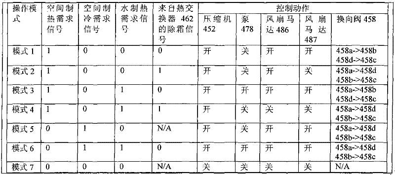
The control model of present embodiment sees Table 3, does not list the control of threeway penstock 375 and 377 in the table, but only under the situation of pattern 6, triple valve just can be sent into cold water storage cistern to the cold water that heat exchanger 356 is come, and other patterns keep linking to each other with boiler without exception.
Table 3
1 expression " having " in the table, 0 expression " nothing ", N/A is illustrated in and does not consider this signal in this pattern.
Embodiment seven
Referring to Figure 11.Present embodiment and embodiment six are basic identical, and unique difference is water-cooled heat exchanger 456 is positioned on the external circuit, and air-cooled type heat exchanger 462 is positioned on the home loop.
The control model of present embodiment sees Table 4
Table 4
1 expression " having " in the table, 0 expression " nothing ", N/A is illustrated in and does not consider this signal in this pattern.
Embodiment eight
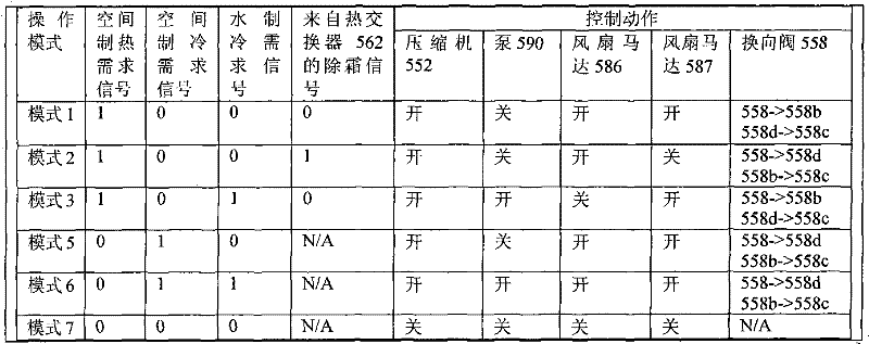
Referring to Figure 12.Present embodiment and embodiment seven are basic identical, and unique difference is among the embodiment seven that the heat exchanger of external circuit is a heat absorption heat exchanger 456, between the inflow end of exhaust outlet of compressor and changeable valve combination; The heat exchanger of external circuit is a heat release heat exchanger 588 in the present embodiment, between the outflow end of compressor air suction mouth and changeable valve combination.
The control model of present embodiment sees Table 5
Table 5
1 expression " having " in the table, 0 expression " nothing ", N/A is illustrated in and does not consider this signal in this pattern.
Embodiment nine
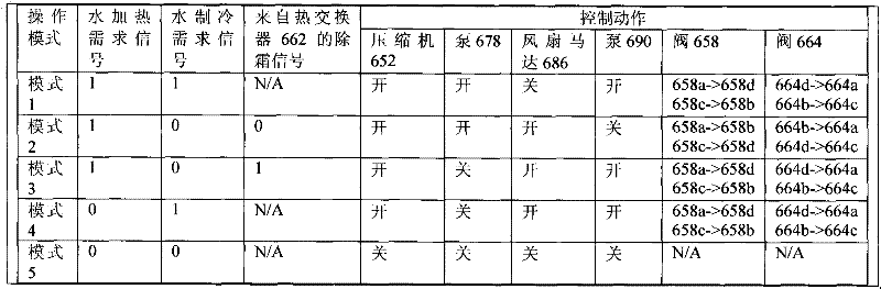
Referring to Figure 13.The heat-exchange system 680 of present embodiment comprises a compressor 652, three heat exchangers 656,662,688, an expansion valve 668 and two solenoid operated four-way valves 658,664, wherein solenoid operated four-way valve 658 and 664 respectively has four port abcd, all is linked as the loop by pipeline with upper-part.Concrete loop is as follows: the exhaust outlet of compressor 652 links to each other with heat exchanger 656 by pipeline 654a; Heat exchanger 656 further links to each other with the upper port 658a of solenoid operated four-way valve 658; The left port 658b of solenoid operated four-way valve 658 is by the left port 664b of pipeline 670 another solenoid operated four-way valves 664 of connection, and the upper port 664a of solenoid operated four-way valve 664 successively links to each other with the lower port 658c of expansion valve 668, heat exchanger 688, solenoid operated four-way valve 658 by pipeline 666a, 666b, 666c; The right output port 658d of solenoid operated four-way valve 658 links to each other with the right output port 664d of heat exchanger 662 with solenoid operated four-way valve 664 by pipeline 660a, 660c; Thereby the lower port 664c of solenoid operated four-way valve 664 links to each other with the air entry of compressor 652 by pipeline 672 and finishes circulation.By above description as can be known, the changeable valve combination of present embodiment is made up of two solenoid operated four-way valves 658,664, and wherein 658 upper port 658a is for flowing into end, and 664 lower port 664c is an outflow end, and with compressor 652, heat exchanger 656 is formed the external circuit; All the other ports are the shunting end, form home loop with expansion valve 668, heat exchanger 662,668.
During the present embodiment operation, refrigerant is from compressor 652, the heat exchanger 656 of flowing through, enter home loop from 658a, two kinds of selections are arranged in home loop, the path is respectively 658a-658b-664b-664a-668-688-658c-658d-662-664d-664c, or 658a-658d-662-664d-664a-668-688-658c-658b-664b-664c, get back to the external circuit from 664c then, and get back to compressor 652, finish circulation.In this running, heat exchanger 656 is always the heat release heat exchanger, and 688 are always the heat absorption heat exchanger, and their effect is constant; Heat exchanger 662 can become the heat release heat exchanger according to different Path selection, also can become the heat absorption heat exchanger.So present embodiment can switch between these two kinds of patterns.
Heat exchanger 656 has a boiler (not shown) as thermal storage device, and heat exchanger 688 has a cold water storage cistern (not shown) as thermal storage device.Pump 678 is made the water circulation opposite with the refrigerant flow direction between heat exchanger 656 and its boiler; Pump 690 is made the water circulation opposite with the refrigerant flow direction between heat exchanger 688 and its cold water storage cistern.Heat exchanger 662 circulates by air-flow by fan motor 686.
It is worthy of note that the heat exchanger 656 in this example can be placed on shown in Figure 13 on the position, also can be placed on the pipeline 666a; Heat exchanger 662 can be placed on the position shown in Figure 13, also can be placed on the pipeline 670, and heat exchanger 688 can be placed on the position shown in Figure 13, also can be placed on the pipeline 672.Because three heat exchangers respectively have two kinds of selectable positions, through permutation and combination, in fact present embodiment has 8 kinds of line arrangement modes.
By microprocessor control, control model sees Table 6 to present embodiment equally.
Table 6
1 expression " having " in the table, 0 expression " nothing ", N/A is illustrated in and does not consider this signal in this pattern.
Embodiment ten
Referring to Figure 14, present embodiment is actually one of distortion of embodiment nine.Difference is in this example that heat exchanger 656 is positioned on the pipeline of shunting between end 664a and the expansion valve 668.As seen, this example is that a changeable valve combination is enough complicated, comprise eight ports, thereby all heat exchangers all places the embodiment of home loop.Present embodiment is in operation, and heat exchanger 656 is always the heat release heat exchanger, and 688 are always the heat absorption heat exchanger, and their effect is constant; Heat exchanger 662 can become the heat release heat exchanger according to different Path selection, also can become the heat absorption heat exchanger.So present embodiment can switch between these two kinds of patterns.
Other the method for operation, control mode are all consistent with embodiment nine, repeat no more.
The foregoing description helps the understanding to technical scheme, but is not the restriction to the utility model protection domain.Understanding to technical scheme should be conceived to the thermodynamic cycle system, also may set up other less important valves in using as reality, but these less important valves are not included in " changeable valve combination ", does not also influence the division to home loop and external circuit; And for example also may be provided with branch road in the practical application, but these branch roads can not influence by compressor all heat exchangers, the cold medium flux of expansion valve.These are all within the utility model scope.