CN201723898U - Composite bidirectional compensator - Google Patents
Composite bidirectional compensator Download PDFInfo
- Publication number
- CN201723898U CN201723898U CN2010201118474U CN201020111847U CN201723898U CN 201723898 U CN201723898 U CN 201723898U CN 2010201118474 U CN2010201118474 U CN 2010201118474U CN 201020111847 U CN201020111847 U CN 201020111847U CN 201723898 U CN201723898 U CN 201723898U
- Authority
- CN
- China
- Prior art keywords
- pipe
- outer sleeve
- casing pipe
- anticorrosive casing
- binder
- Prior art date
- Legal status (The legal status is an assumption and is not a legal conclusion. Google has not performed a legal analysis and makes no representation as to the accuracy of the status listed.)
- Expired - Fee Related
Links
Images
Abstract
The utility model relates to a composite bidirectional compensator which belongs to the field of a heat distribution pipeline compensating device. The composite bidirectional compensator comprises a heat insulation spacer, an anticorrosion casing pipe fixing beam, anticorrosion casing pipes, a gland packing combination casing element, sealing filler A, a material pressing ring, sealing filler B, a steel ball, a corrugated pipe, a outer casing pipe, an insulating layer, bolts, an inner pipe, an steel ball, an inner cushion cap of an outer casing pipe, a convex ring of an inner pipe, and a stream guiding pipe, wherein the inner side of the outer casing pipe is provided with the inner cushion cap of an outer casing pipe, and the outer ring of the inner pipe is respectively provided with the anticorrosion casing pipe fixing beam and the convex ring of an inner pipe; the space formed by the end faces of the inner cushion cap of an outer casing pipe and the gland packing combination casing element, the inside side of the outer casing pipe, and the outer ring of the inner pipe is provided with the sealing filler A; the gland packing combination casing element, the outer ring of the sealing filler B, and the outer casing pipe of the anticorrosion casing pipe fixing beam are provided with the anticorrosion casing pipes, and the inside sides of the corrugated pipe and the inner pipe are provided with a stream guiding pipe. The structure can ensure that the inner pipe and the anticorrosion casing pipe anticorrosion casing pipe move between left and right along with the expansion and the contraction of the corrugated pipe. The sealing performance is more reliable, and the utility model can serve as direct-buried pipelines or overhead pipelines.
Description
Technical field
The present invention relates to a kind of compound bidirectional compensating device, belong to the technical field of heat distribution pipeline compensation device, belong to the technical field of the heat distribution pipeline compensation device structure of using in the industries such as oil, chemical industry, light industry, heating power, metallurgy specifically.
Background technique
Heat distribution pipeline must cause expanding with heat and contract with cold of pipeline because of the medium temperature of transmission changes, and the pipeline dilatation is to occur with end thrust that is unfavorable for the pipe safety operation or axial displacement form.Under the normal conditions, all be provided with the compensation of pipeline device in the heat distribution pipeline to absorb or the compensation pipe deforming.The pipeline compensator of prior art has multiple structural type, all has to absorb or compensation pipeline deformation ability.Common in the market have following several compensator: 1. spherical compensator, 2. utilize FlexbleJoint (the tubulose elastic sensing element of bellows of bellows for connecting into along the folding retractable direction with collapsible wrinkle sheet.Its opening end is fixed, and sealed end is in free state, and utilizes auxiliary helical spring or reed to increase elasticity.In the elongation of the effect lower edge of internal pressure tube length direction, make movable end produce the displacement that becomes certain relation with pressure during work.Bellows mainly is divided into metal (stainless steel, carbon steel) bellows, plastic film capicitor.Metal bellows is mainly used in effects such as compensation pipes thermal distortion, damping, absorption pipeline sedimentation and deformation, is widely used in industries such as petrochemical industry, instrument, space flight, chemical industry, electric power, cement, metallurgy.Other material bellowss such as plastics have irreplaceable effect in fields such as medium transport, electric power threading, lathe, household electrical appliances.), 3. slip-type expansion joint, 4. whirl compensator.Wherein: external import spherical compensator cost is too high, and the spherical compensator performance of domestic production is general, and crushing is bigger.FlexbleJoint pipe stress in actual applications is excessive, the pipeline potential safety hazard that exists all the time in service; And with adopt original ∏ shape nature compensation way the same invest and the pressure loss all bigger.The structure and the sealability of slip-type expansion joint are not good enough, and leakage phenomenon is more serious, and be weak aspect anticorrosion link yet.The whirl compensator performance is more outstanding; Have that compensation rate is big, flexible arrangement, particularly application advantageization is more obvious in long defeated aerial pipeline; But also exist not enough: the one, the junction excesssive gap of interior pipe and reducer pipe can produce eddy current at this position in the flowing medium motion, has so just increased the pressure loss of flowing medium.The 2nd, whirl compensator is used when arranging in pipeline and must be taken certain space because structure is a working principle radially; And every group of compensator mounting points all must add drain valve; The cost and the crushing of pipe network have been increased so again; Especially at all can't widespread usage on buried pipeline; Sleeve expansion joint and whirl compensator all are to adopt single packing seal form in addition, and medium is limited in the use.
Summary of the invention
The invention provides a kind of compound bidirectional compensating device.To realize solving the deficiency of existing several compensators; Reach and to realize eliminating pipe stress, strengthen sealability, possess preservative efficacy, can realize the large compensation amount, enlarge Applicable scope and multi-functional characteristics; Reduce investment outlay and operating cost, really make pipeline security of operation, reliable, purpose of energy saving.
Technological scheme of the present invention is in order to achieve the above object:
A kind of compound bidirectional compensating device comprises cushion cap, the protruding outer shroud of interior pipe and honeycomb duct at least one heat insulating washer, anticorrosive casing pipe fixed beam, anticorrosive casing pipe, binder combination set, A stuffing box packing, binder ring, B stuffing box packing, steel ball, bellows, outer sleeve, thermal insulation layer, bolt, interior pipe, the outer sleeve;
Pipe is cylindrical-shaped structure in described, protruding outer shroud of pipe and anticorrosive casing pipe fixed beam in the two ends outer ring surface of pipe is set with respectively in being somebody's turn to do, the protruding outer shroud of interior pipe cross section is provided with groove for the rectangular configuration outer ring surface, and rolling is provided with at least one steel ball and supports extremely described outer sleeve inner wall in this groove;
Described outer sleeve is a cylindrical-shaped structure, and inner ring surface is convexly equipped with and is equipped with cushion cap at least one outer sleeve; Managing outer ring surface in the two ends of inserting this outer sleeve respectively of two described interior tube hub symmetries, this outer sleeve in the cushion cap contact also manages between protruding outer shroud and the anticorrosive casing pipe fixed beam in described; The two-port place outer ring surface of this outer sleeve protrudes the fixedly connected circular binder ring that is provided with respectively;
Described honeycomb duct is a cylindrical-shaped structure, is sheathed in the described outer sleeve, and its two ends are an end of the described interior pipe of symmetry insertion respectively, and this honeycomb duct one end and interior pipe are fixed; Described bellows is positioned at the space that this outer sleeve inner ring surface and honeycomb duct outer ring surface surround, the two ends of this bellows respectively with described in the protruding outer shroud contact of pipe and fixedly connected with the corresponding port of pipe in this;
Described binder combination set is a ring-type, and its sectional shape is L type or L symmetric form, be located on described in pipe outer ring surface and in described outer sleeve between cushion cap and the anticorrosive casing pipe fixed beam; This binder combination set outer shroud port is provided with L type recess, and the corresponding inner ring surface that contacts with inner tube outer surface is provided with annular groove, at least one steel ball roll be arranged in the described annular groove and with interior tube-surface contact; The common Baltimore groove that forms of this L type recess and this binder ring, described Baltimore groove is built-in with the A stuffing box packing; Described B stuffing box packing be arranged in binder combination set L type one end and the described outer sleeve between the cushion cap and respectively with its contact;
Described anticorrosive casing pipe axial cross section is shaped as the trench structure to a side opening, opening one end ring is enclosed within the common outer ring surface of forming of this binder ring, A stuffing box packing and binder combination set, the grooved bottom end evenly is provided with at least one through hole, be fastenedly connected by at least one bolt and described anticorrosive casing pipe fixed beam, between described anticorrosive casing pipe grooved bottom end and the anticorrosive casing pipe fixed beam surface of contact heat insulating washer be set;
Described outer sleeve outer surface is around thermal insulation layer being set, the described binder ring of the two ends contact of this thermal insulation layer; Form bellows when flexible, manage the structure that axially moves with anticorrosive casing pipe in making along outer sleeve, the axial coaxial synchronous integral body of binder combination set.
This binder combination set annular end face one side is fixedlyed connected with the termination of described outer sleeve.
Cushion cap and this outer sleeve are structure as a whole at least one outer sleeve that is provided with on the described outer sleeve; Pipe, the protruding outer shroud of interior pipe, anticorrosive casing pipe fixed beam and anticorrosive casing pipe can be with the flexible structures of carrying out the right left side of bi-directional synchronization or left and right displacement of bellows in forming.
This outer sleeve and honeycomb duct interlayer are provided with bellows; The bellows two ends is welded to connect fixing with the side head employing of corresponding interior pipe respectively.
This B stuffing box packing is positioned at outer sleeve cushion cap and corresponding end face of binder combination set and the inboard space that surrounds jointly with the pipe outer shroud of outer sleeve.
The common groove that forms of this binder combination set and binder ring, groove is built-in with the A stuffing box packing and withholds contact anticorrosive casing pipe inwall.
This outer sleeve termination and the employing of binder ring are welded to connect fixing.
Cushion cap finally is an overall structure with corresponding in this outer sleeve, the outer sleeve; Interior Guan Yiduan is equipped with the anticorrosive casing pipe fixed beam outward, the protruding outer shroud of pipe in the other end is equipped with outward, and the protruding outer shroud outer ring surface of interior pipe is provided with a groove, and groove is built-in with steel ball contact outer sleeve inner wall; Be provided with bellows between interior pipe and corresponding both end faces; Be provided with the B stuffing box packing in the chamber between interior pipe outer shroud and the outer sleeve inboard, B stuffing box packing one end presses cushion cap end face in the outer sleeve, the binder end of the other end contact binder combination set; The binder combination set is provided with a groove facing to the inboard of interior pipe outer ring surface, and groove is built-in with pipe outer shroud in the steel ball contact; The binder combination set is equipped with a L shaped recess outward; The common groove that forms of L shaped recess and binder ring, groove are built-in with end packing material contact anticorrosive casing pipe inwall; Binder combination set and outer sleeve adopt to connect to weld and are connected and fixed.The outer integral body that is equipped with of binder ring and A stuffing box packing and binder combination set and anticorrosive casing pipe fixed beam is L shaped anticorrosive casing pipe; Anticorrosive casing pipe fixed beam outer end is provided with the bolt hole that can wear a plurality of bolts, and the short end of L shaped anticorrosive casing pipe is provided with anticorrosive casing pipe fixed beam outer end with the heat insulating washer end face and is provided with the corresponding through hole of a plurality of bolts, adopts bolt to link closely and is connected and fixed;
The structure that this compound bidirectional compensating device integral body is centrosymmetric, along with the cross section of axis normal with outer sleeve, the left and right sides two-part after bellows and honeycomb duct disconnect from the center are that identical in structure symplex structure (abbreviating A group and B group as) is combined to form; The interior pipe and the bellows of (A, B group) finally are an overall structure; Honeycomb duct is located in interior pipe and the bellows; One end and the interior pipe of honeycomb duct are welded to connect fixing.Interior pipe, the protruding outer shroud of interior pipe, steel ball and anticorrosive casing pipe fixed beam and anticorrosive casing pipe and corresponding assembly can be with a flexible right synchronously left side, the left and right displacement of carrying out of bellows.Be provided with thermal insulation layer between (A, B group) both binder ring end faces.Described bidirectional composite type compensator L shaped long end of (A, B group) anticorrosive casing pipe after absorbing thermal walking is buckled in the outer shroud of thermal insulation layer.
The outer end of described outer sleeve inboard is provided with cushion cap in the outer sleeve; Be provided with stuffing box packing in the common regional space that forms in cushion cap and binder combination set end face and interior pipe outer shroud and the outer sleeve in the outer sleeve.
Outer anti-corrosion pipe fixedly collar tie beam and the protruding outer shroud of interior pipe of being equipped with of pipe in described; Be provided with bellows between interior pipe and corresponding both end faces; The protruding outer shroud outer ring surface of interior pipe is provided with groove, and groove is built-in with steel ball contact outer sleeve inner wall.
The outer end of described binder combination set is provided with a groove facing to the inboard of interior pipe outer ring surface, and groove is built-in with pipe outer shroud in the steel ball contact; The common groove that forms of the L shaped recess of binder combination set outer shroud and binder ring is built-in with stuffing box packing contact anticorrosive casing pipe inwall; Binder combination set and outer sleeve employing are welded to connect fixing.
It is fixing that described binder ring and outer sleeve and binder combination set press employing to be welded to connect; The outer integral body that is equipped with of binder ring and binder combination set and anticorrosive casing pipe fixed beam is L shaped anticorrosive casing pipe.
Survey in the L shaped long end of described anticorrosive casing pipe and be held in the stuffing box packing outer shroud; Be provided with heat insulating washer between anticorrosive casing pipe fixed beam and anticorrosive casing pipe end face; Anticorrosive casing pipe, heat insulating washer end face are provided with several bolts hole, link closely fixing with the anticorrosive casing pipe fixed beam the L shaped short end of anticorrosive casing pipe by bolt.
Be provided with thermal insulation layer between described binder ring and corresponding both end faces; The L shaped long end cover of (A, B group) anticorrosive casing pipe is buckled in the outer shroud of thermal insulation layer after described compound bidirectional compensating device absorbs thermal walking.
But pipe, the protruding outer shroud of interior pipe, steel ball and anticorrosive casing pipe fixed beam and anticorrosive casing pipe and corresponding assembly bi-directional synchronization are carried out a left side, the right side, left and right displacement in described.
Adopt the standard of technological scheme root a tree name city heat supply compensator of the present invention and the standard of weldering system sleeve expansion joint, at the operating race of pipeline, emit, let out, problem such as leakage, with the advantage combination of FlexbleJoint, sleeve expansion joint and whirl compensator, owing to comprising heat insulating washer, preventing that rotten fixed beam, anticorrosive casing pipe, binder combination set, stuffing box packing, binder ring, steel ball, bolt, outer sleeve, the interior cushion cap of outer sleeve, bellows, interior pipe, the protruding outer shroud honeycomb duct of interior pipe and the thermal insulation layer composition (abbreviating the A group as) of managing of cover is combined to form an integral body with (B group).Wherein: the outer sleeve inboard is provided with cushion cap in the outer sleeve; Interior pipe is outer to be equipped with anticorrosive casing pipe fixed beam and the protruding outer shroud of interior pipe, and the protruding outer shroud outer ring surface of interior pipe is provided with a groove, and groove is built-in with steel ball; Be provided with the B stuffing box packing in the space that cushion cap and binder combination set end face and outer sleeve are inboard and interior pipe outer shroud forms jointly in the outer sleeve; The inboard of binder combination set is provided with a groove facing to interior pipe outer ring surface, and groove is built-in with plural steel ball; Binder combination set and outer sleeve employing are welded to connect fixing; The common groove that forms of L shaped recess of binder combination set outer shroud and binder ring is built-in with A stuffing box packing contact anticorrosive casing pipe inwall; Be provided with thermal insulation layer between binder ring and corresponding both end faces; The outer integral body that is equipped with of binder ring and binder combination set and anticorrosive casing pipe fixed beam is L shaped anticorrosive casing pipe.Be provided with heat insulating washer between anticorrosive casing pipe fixed beam and anticorrosive casing pipe end face.Anticorrosive casing pipe, heat insulating washer end face are provided with several bolts hole, link closely fixing with the anticorrosive casing pipe fixed beam the L shaped short end of anticorrosive casing pipe by bolt.Survey in the L shaped long end of anticorrosive casing pipe and be held in A stuffing box packing outer shroud.Cushion cap finally is an overall structure with corresponding with outer sleeve in the outer sleeve; The interior pipe and the bellows of (A, B group) finally are an overall structure; Honeycomb duct is located in interior pipe and the bellows; One end of honeycomb duct and interior pipe connect weldering and are connected and fixed.Interior pipe, the protruding outer shroud of interior pipe and anticorrosive casing pipe finally are an overall structure, and the steel ball in can with the telescopic band of bellows in the protruding outer shroud outer ring surface groove of pipe carry out a left side, the right side, left and right displacement synchronously.Adopt such structure to have the elimination pipe stress, strengthen sealability, possess preservative efficacy, can realize the large compensation amount, enlarge Applicable scope and multi-functional characteristics; Reduce investment outlay and operating cost, really make pipeline security of operation, reliable, purpose of energy saving.
Description of drawings
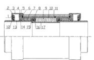
Fig. 1 absorbs thermal walking pre-structure schematic representation for the present invention.
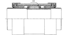
Fig. 2 absorbs structural representation after the thermal walking for the present invention.
Description of reference numerals:
1. heat insulating washer
2. anticorrosive casing pipe fixed beam
3. anticorrosive casing pipe
4. binder combination set
5.A stuffing box packing
6. binder ring
7.B stuffing box packing
8. steel ball
9. bellows
10. outer sleeve
11. thermal insulation layer
12. bolt
13. interior pipe
14. steel ball
15. cushion cap in the outer sleeve
16. the protruding outer shroud of interior pipe
17. honeycomb duct
Embodiment:
Below in conjunction with accompanying drawing technological scheme of the present invention is described in detail as follows.
As shown in Figure 1, compound as can be seen from Figure bidirectional compensating device comprises cushion cap 15 at least one heat insulating washer 1, anticorrosive casing pipe fixed beam 2, anticorrosive casing pipe 3, binder combination set 4, A stuffing box packing 5, binder ring 6, B stuffing box packing 7, steel ball 8, bellows 9, outer sleeve 10, thermal insulation layer 11, bolt 12, interior pipe 13, steel ball 14, the outer sleeve, the protruding outer shroud 16 of interior pipe, honeycomb duct 17 compositions.
Described outer sleeve 10 is a cylindrical-shaped structure, inner ring surface is convexly equipped with and (for example is equipped with the interior cushion cap 15 of at least one outer sleeve, as Fig. 1, cushion cap 15 in the outer sleeve that the interior ring surface at outer sleeve 10 shown in Figure 2 is convexly equipped with symmetrically near center, place, two ends and puts two cross sections is rectangle); Two described interior 13 centrosymmetric two ends of inserting this outer sleeve 10 respectively from two ends of managing are managed 13 outer ring surfaces and are managed between protruding outer shroud 16 and the anticorrosive casing pipe fixed beam 2 in described in cushion cap 15 covers are buckled in this outer sleeve; The two-port place outer ring surface of this outer sleeve 10 protrudes respectively, and fixedly connected (for example welding) is provided with circular binder ring 6, make outer sleeve 10 and binder ring 6 state (Fig. 1) that meets at right angles, whole outer sleeve 10 constitutes grooved (ㄩ type) structures with the binder ring 6 that two ends are provided with, and thermal insulation layer 11 is set in this grooved (ㄩ type) structure and the binder ring 6 of contact both sides and withhold outer sleeve 10 outer surfaces;
Described honeycomb duct 17 is a cylindrical-shaped structure, be located in the described outer sleeve 10 (be outer sleeve 10 be enclosed within honeycomb duct 17 outer), the two ends of honeycomb duct 17 respectively symmetry insert described in an end and the overlap joint with it of pipe 13, an end of this honeycomb duct 17 is fixed with interior pipe 13; Described bellows 9 is a tubular structure, be positioned at these outer sleeve 10 inner ring surfaces and enclose the space that (shape) becomes with honeycomb duct 17 outer ring surfaces, fixedly connected with described interior protruding outer shroud 16 contacts of pipe and with pipe 13 corresponding ports in this respectively in the two ends of this bellows 9, should interiorly manage the port that protruding outer shroud 16 is arranged at interior pipe 13, can flush (as Fig. 1, Fig. 2) with port;
Described binder combination set 4 is a ring-type, its sectional shape is L type or L symmetric form, be located on described in pipe 13 outer ring surface and in described outer sleeve between cushion cap 15 and the anticorrosive casing pipe fixed beam 2, binder combination set 4 outer ring surfaces are that hitch contacts with anticorrosive casing pipe 3 inner ring surfaces, and binder combination set 4 inner ring surfaces contact with interior pipe 13 outer surface hitch; These binder combination set 4 outer shroud ports (or a side) are provided with L type recess, this L type recess and this binder ring 6 common Baltimore grooves that form, and described Baltimore groove is built-in with ring-type A stuffing box packing 5; The inner ring surface that these binder combination set 4 corresponding and interior pipe 13 outer surfaces contact is provided with annular groove, at least one steel ball 14 roll be arranged in the described annular groove and with interior pipe 13 outer surface contacts (or being the state that rolls and withhold); Described B stuffing box packing 7 be arranged in binder combination set 4L type one end (the short end of L type can be I shape as the short end portion of Fig. 1 L type cross section) and the described outer sleeve between the cushion cap 15 and respectively with its contact;
Described anticorrosive casing pipe 3 axial cross sections are shaped as the trench structure (axially the half section is shaped as the L type) to a side opening, opening one end ring is enclosed within this binder ring 6, A stuffing box packing 5 and the binder combination set 4 common outer ring surfaces of forming, the grooved bottom end evenly is provided with at least one through hole, be fastenedly connected with described anticorrosive casing pipe fixed beam 2 (corresponding at least one through hole that also evenly is provided with of its end face) by at least one bolt 12, between described anticorrosive casing pipe 3 grooved bottom ends and anticorrosive casing pipe fixed beam 2 surface of contact heat insulating washer 1 be set;
Described outer sleeve 10 outer surfaces are around thermal insulation layer 11 being set, the described binder ring 6 of the two ends contact of this thermal insulation layer 11; Form bellows 9 when flexible, pipe 13 and the anticorrosive casing pipe 3 axial structures that move along outer sleeve 10, binder combination set 4 axial coaxial synchronous integral body in making.
This binder combination set 4 annular end faces one side (L type interior edge face, as Fig. 1, outer sleeve 10 terminations shown in Figure 2 can be overlapped on the short end face of binder combination set 4L type and contact is lived the long end face of corresponding L type, and the end face that contact is lived is a L type interior edge face) fixedly connected (for example being welded to connect) with the termination of described outer sleeve 10.
This outer sleeve 10 and honeycomb duct 17 interlayers are provided with bellows 9; Bellows 9 two ends are welded to connect fixing with the side head employing of corresponding interior pipe 13 respectively.
This B stuffing box packing 7 is positioned at outer sleeve cushion cap 15 and binder combination set 4 both corresponding (or relatively) end faces and the outer sleeve 10 inboard spaces that surround jointly with pipe 13 outer shrouds, and respectively with it contact withhold.
This binder combination set 4 and the binder ring 6 common grooves that form, groove is built-in with A stuffing box packing 5 contact anticorrosive casing pipes 3 inwalls.
These outer sleeve 10 terminations and binder combination set 4 and 6 employings of binder ring are welded to connect fixing.
From Fig. 1 and Fig. 2 as can be seen, the structure that compound bidirectional compensating device integral body described in the invention is centrosymmetric, along with the cross section of axis normal with outer sleeve 10, the integral body that to be identical in structure symplex structures (abbreviating the A group as) be combined to form with (B group) of the two-part after bellows 9 and honeycomb duct 17 disconnect from the center.
In conjunction with Fig. 1 and Tu, the outer sleeve inboard is provided with cushion cap in the outer sleeve in sum; Interior pipe is outer to be equipped with anticorrosive casing pipe fixed beam and the protruding outer shroud of interior pipe, and the protruding outer shroud outer ring surface of interior pipe is provided with a groove, and groove is built-in with steel ball; Be provided with the B stuffing box packing in the space that cushion cap and binder combination set end face and outer sleeve are inboard and interior pipe outer shroud forms jointly in the outer sleeve; The inboard of binder combination set is provided with a groove facing to interior pipe outer ring surface, and groove is built-in with plural steel ball; Binder combination set and outer sleeve employing are welded to connect fixing; The common groove that forms of L shaped recess of binder combination set outer shroud and binder ring is built-in with A stuffing box packing contact anticorrosive casing pipe inwall; Be provided with thermal insulation layer between binder ring and corresponding both end faces; Binder ring and binder combination set and anticorrosive casing pipe fixed beam outer be equipped with one vertically the half section be L shaped anticorrosive casing pipe.Be provided with heat insulating washer between anticorrosive casing pipe fixed beam and anticorrosive casing pipe end face.Anticorrosive casing pipe, heat insulating washer end face are provided with a plurality of bolts hole, link closely fixing with the anticorrosive casing pipe fixed beam the L shaped short end of anticorrosive casing pipe by bolt.Survey in the L shaped long end of anticorrosive casing pipe and be held in A stuffing box packing outer shroud.Cushion cap finally is an overall structure with corresponding with outer sleeve in the outer sleeve; The interior pipe and the bellows of (A, B group) finally are an overall structure; Honeycomb duct is located in interior pipe and the bellows; One end and the interior pipe of honeycomb duct are welded to connect fixing.Interior pipe, the protruding outer shroud of interior pipe and anticorrosive casing pipe finally are structure as a whole, and the steel ball in can with the telescopic band of bellows in the protruding inner annular recess of pipe carry out a left side, the right side, left and right displacement (as shown in Figure 2) synchronously.
Adopt such structure to have the elimination pipe stress, strengthen sealability, possess preservative efficacy, energy
Realize the large compensation amount, enlarge Applicable scope and multi-functional characteristics; Reduce investment outlay and operating cost, really make pipeline security of operation, reliable, purpose of energy saving.
Technological scheme of the present invention when implementing because in the outer sleeve 10, outer sleeve cushion cap 15 be structure as a whole; Interior pipe 13, the protruding outer shroud 16 of interior pipe are structure as a whole, and also can become one structure by technological methodes such as for example welding; When mounted:
The first step is welded to connect bellows 9 one ends and interior pipe 13 fixing; Be with steel ball 8 to insert together in outer sleeve 10 cylindrical shells bellows 9, interior pipe 13, the protruding outer shroud 16 of interior pipe then, be welded to connect the interior pipe of the bellows 9 and the other end fixing simultaneously; Then honeycomb duct 17 is inserted in interior pipe 13 and the bellows 9; Simultaneously honeycomb duct 17 is welded to connect the specified position (honeycomb duct 17 1 ends are fixed in the interior pipe of a side) that is fixed on interior pipe 13.
Second step was put steel ball in the annular groove of 16 corresponding of the protruding outer shrouds of interior pipe; Then with the cylindrical shell hitch of 15 corresponding of cushion caps in outer sleeve 10, the outer sleeve cylindrical shell outer shroud to 13 corresponding of interior pipes, the outer sleeve that can consider two-part are wholely set cushion cap 15 in outer sleeve hitch respectively closely connects the mode combination sleeve pipe 10 of (for example welding) in corresponding with the centre behind the pipe 13 staving outer shrouds.
The 3rd groove of step between outer sleeve 10 and interior pipe 13 is embedded in stuffing box packing 7, makes the stuffing box packing 7 interior edge faces interior cushion cap 15 of outer sleeve that links closely; Then binder combination set 4 is being with steel ball 14 hitch to interior pipe 13 cylindrical shell outer shrouds, utilize pressurized equipment to impel the stuffing box packing 7 of linking closely of the binder end of binder combination set 4 simultaneously, and the interior edge face that makes binder combination set 4 and the termination of outer sleeve 10 reach combine substantially be welded to connect simultaneously fixing.
The 4th step and the corresponding the other end of the 3rd corresponding operation same operation of step.
The anticorrosive casing pipe fixed beam 2 that the 5th step will have a plurality of even distribution bolts hole is soldered to interior fixed position of managing 13 outer ring surfaces, then place heat insulating washer 1 in the exterior edge face of anticorrosive casing pipe fixed beam 2, after will have outer shroud with anticorrosive casing pipe 3 hitch of the corresponding plurality of through holes of anticorrosive casing pipe fixed beam 2 end faces this binder combination set 4 to the interior pipe 13, make inboard, anticorrosive casing pipe 3 one end limit be tight against heat insulating washer 1, utilize bolt 12 (for example countersunk screw) that anticorrosive casing pipe 3 and anticorrosive casing pipe fixed beam 2 are closely fixed (bolt) simultaneously.
The 6th step and the corresponding the other end of the 5th corresponding operation same operation of step.
The 7th step placed in the common groove that forms of the L shaped recess of binder combination set 4 outer shrouds and anticorrosive casing pipe 3 inwalls and holds A stuffing box packing 5, utilize pressurized equipment to impel binder ring 6 to be tight against the end face of A stuffing box packing 5 then, weld binder ring 6 and outer sleeve 10 termination outer shroud facial canals fixing simultaneously.
The 8th step and the corresponding the other end of the 7th corresponding operation same operation of step.
The 9th step was carried out the coating operation of thermal insulation layer 11.Carry out the corrosion resistant clad work of metal exsertion part at last; (comprise spraying, be coated with and rinse anticorrosive material).
This technology and structure with the product that assembles axially from the actual formation of intermediate section bilateral symmetry structure, about can be called the A group and B organizes:
1. cushion cap 15 finally becomes an overall structure with (B group) corresponding in described (A group) outer sleeve 10, the outer sleeve; For the protruding outer shroud 16 of interior pipe 13, interior pipe, steel ball 8 and the anticorrosive casing pipe 3 of (A group) with corresponding (B group) part carries out a right synchronously left side, left and right displacement provides necessary condition.
2. pipe 13 finally becomes an overall structure with (B group) corresponding and bellows 9 in described; It is logical to have determined that at first entire equipment does not have leakage.
3. described steel ball 8, steel ball 14 and corresponding (B group) assembly; Played and played the coaxial effect of setting upright, reduce frictional resistance when interior pipe 13 parts such as grade carry out a right synchronously left side, left and right displacement with corresponding (B group) assembly.
4. described A stuffing box packing 5, B stuffing box packing 7 and corresponding (B group) assembly abbreviate as: (fixing seals), it has anchor ring and the multi-sealed effect of end face.And it has the lubrication when part such as interior pipe 13 and corresponding (B group) part carry out a right left side, left and right displacement.
5. described thermal insulation layer 11, heat insulating washer 1 and anticorrosive casing pipe 3 have played anticorrosive heat insulating, insulation, the effect of saving energy to primary structural component.
6. pipe 13 is an overall structure with (B group) corresponding and bellows 9 in described; Enlarged Applicable scope; Corresponding anti-slip function of pipe protruding outer shroud 16 and (B group) improved safety guarantee in adding.
7. described bellows 9 adds that A stuffing box packing 5 combines the multi-sealed of end face with the anchor ring of B stuffing box packing 7 and corresponding (B group) part; Make sealability more reliable.
8. pipe 13 and (B group) corresponding left, the left and right displacement in the right side synchronously in described; Play the compensation rate increase, reduced the effect of stuffing box packing abrasion.
Claims (7)
1. a compound bidirectional compensating device is characterized in that: comprise cushion cap, the protruding outer shroud of interior pipe and honeycomb duct at least one heat insulating washer, anticorrosive casing pipe fixed beam, anticorrosive casing pipe, binder combination set, A stuffing box packing, binder ring, B stuffing box packing, steel ball, bellows, outer sleeve, thermal insulation layer, bolt, interior pipe, the outer sleeve;
Pipe is cylindrical-shaped structure in described, protruding outer shroud of pipe and anticorrosive casing pipe fixed beam in the two ends outer ring surface of pipe is set with respectively in being somebody's turn to do, the protruding outer shroud of interior pipe cross section is provided with groove for the rectangular configuration outer ring surface, and rolling is provided with at least one steel ball and supports extremely described outer sleeve inner wall in this groove;
Described outer sleeve is a cylindrical-shaped structure, and inner ring surface is convexly equipped with and is equipped with cushion cap at least one outer sleeve; Manage outer ring surface in cushion cap is set in the two ends of inserting this outer sleeve respectively of two described interior tube hub symmetries, this outer sleeve and in described, manage between protruding outer shroud and the anticorrosive casing pipe fixed beam; The two-port place outer ring surface of this outer sleeve protrudes the fixedly connected circular binder ring that is provided with respectively;
Described honeycomb duct is a cylindrical-shaped structure, is located in the described outer sleeve, and its two ends are an end of described two the interior pipes of symmetry insertion respectively, and this honeycomb duct one end and interior pipe are fixed; Described bellows is positioned at the space that this outer sleeve inner ring surface and honeycomb duct outer ring surface surround, the two ends of this bellows respectively with described in the protruding outer shroud contact of pipe and fixedly connected with the corresponding port of pipe in this;
Described binder combination set is a ring-type, and its sectional shape is L type or L symmetric form, be located on described in pipe outer ring surface and in described outer sleeve between cushion cap and the anticorrosive casing pipe fixed beam; This binder combination set outer shroud port is provided with L type recess, and the corresponding inner ring surface that contacts with inner tube outer surface is provided with annular groove, at least one steel ball roll be arranged in the described annular groove and with interior tube-surface contact; The common Baltimore groove that forms of this L type recess and this binder ring, described Baltimore groove is built-in with the A stuffing box packing; Described B stuffing box packing be arranged in binder combination set L type one end and the described outer sleeve between the cushion cap and respectively with its contact;
Described anticorrosive casing pipe axial cross section is shaped as the trench structure to a side opening, opening one end ring is enclosed within the common outer ring surface of forming of this binder ring, A stuffing box packing and binder combination set, the grooved bottom end evenly is provided with at least one through hole, be fastenedly connected by at least one bolt and described anticorrosive casing pipe fixed beam, between described anticorrosive casing pipe grooved bottom end and the anticorrosive casing pipe fixed beam surface of contact heat insulating washer be set;
Described outer sleeve outer surface is around thermal insulation layer being set, the described binder ring of the two ends contact of this thermal insulation layer; Form bellows when flexible, manage the structure that axially moves with anticorrosive casing pipe in making along outer sleeve, the axial coaxial synchronous integral body of binder combination set.
2. compound bidirectional compensating device as claimed in claim 1 is characterized in that this binder combination set annular one side end face fixedlys connected with the termination of described outer sleeve.
3. compound bidirectional compensating device as claimed in claim 1, cushion cap and this outer sleeve are structure as a whole at least one outer sleeve that it is characterized in that being provided with on the described outer sleeve; Pipe, the protruding outer shroud of interior pipe, anticorrosive casing pipe fixed beam and anticorrosive casing pipe can be with the flexible structures of carrying out the right left side of bi-directional synchronization or left and right displacement of bellows in forming.
4. compound bidirectional compensating device as claimed in claim 1 is characterized in that this outer sleeve and honeycomb duct interlayer are provided with bellows; The bellows two ends is welded to connect fixing with the side head employing of corresponding interior pipe respectively.
5. compound bidirectional compensating device as claimed in claim 1 is characterized in that this B stuffing box packing is positioned at outer sleeve cushion cap and corresponding end face of binder combination set and the inboard space that surrounds jointly with the pipe outer shroud of outer sleeve.
6. compound bidirectional compensating device as claimed in claim 1 is characterized in that the common groove that forms of this binder combination set and binder ring, and groove is built-in with the A stuffing box packing and withholds contact anticorrosive casing pipe inwall.
7. compound bidirectional compensating device as claimed in claim 1 is characterized in that the employing of this outer sleeve termination and binder ring is welded to connect fixing.
Priority Applications (1)
| Application Number | Priority Date | Filing Date | Title |
|---|---|---|---|
| CN2010201118474U CN201723898U (en) | 2010-02-10 | 2010-02-10 | Composite bidirectional compensator |
Applications Claiming Priority (1)
| Application Number | Priority Date | Filing Date | Title |
|---|---|---|---|
| CN2010201118474U CN201723898U (en) | 2010-02-10 | 2010-02-10 | Composite bidirectional compensator |
Publications (1)
| Publication Number | Publication Date |
|---|---|
| CN201723898U true CN201723898U (en) | 2011-01-26 |
Family
ID=43492229
Family Applications (1)
| Application Number | Title | Priority Date | Filing Date |
|---|---|---|---|
| CN2010201118474U Expired - Fee Related CN201723898U (en) | 2010-02-10 | 2010-02-10 | Composite bidirectional compensator |
Country Status (1)
| Country | Link |
|---|---|
| CN (1) | CN201723898U (en) |
Cited By (4)
| Publication number | Priority date | Publication date | Assignee | Title |
|---|---|---|---|---|
| CN102147038A (en) * | 2010-02-10 | 2011-08-10 | 陈墅庚 | Compound type bidirectional compensator |
| CN102330865A (en) * | 2011-07-28 | 2012-01-25 | 大连益多管道有限公司 | Fully fixed one-way outer compensator |
| CN103438320A (en) * | 2013-08-23 | 2013-12-11 | 江苏博格东进管道设备有限公司 | Bi-direction balance type bellows compensator |
| CN111322482A (en) * | 2018-12-13 | 2020-06-23 | 乔治费歇尔管路系统公开股份有限公司 | Length compensator |
-
2010
- 2010-02-10 CN CN2010201118474U patent/CN201723898U/en not_active Expired - Fee Related
Cited By (6)
| Publication number | Priority date | Publication date | Assignee | Title |
|---|---|---|---|---|
| CN102147038A (en) * | 2010-02-10 | 2011-08-10 | 陈墅庚 | Compound type bidirectional compensator |
| CN102147038B (en) * | 2010-02-10 | 2012-07-25 | 陈墅庚 | Compound type bidirectional compensator |
| CN102330865A (en) * | 2011-07-28 | 2012-01-25 | 大连益多管道有限公司 | Fully fixed one-way outer compensator |
| CN103438320A (en) * | 2013-08-23 | 2013-12-11 | 江苏博格东进管道设备有限公司 | Bi-direction balance type bellows compensator |
| CN111322482A (en) * | 2018-12-13 | 2020-06-23 | 乔治费歇尔管路系统公开股份有限公司 | Length compensator |
| CN111322482B (en) * | 2018-12-13 | 2023-03-10 | 乔治费歇尔管路系统公开股份有限公司 | Length compensator |
Similar Documents
| Publication | Publication Date | Title |
|---|---|---|
| CN101832443B (en) | Compound compensator for high pressure pipeline | |
| CN102359683B (en) | Plunger-type double-safety pipeline compensator | |
| CN201723898U (en) | Composite bidirectional compensator | |
| CN104329529A (en) | Novel precision-type high-pressure-resistant rotary compensator | |
| CN101608726B (en) | Two-way multifunctional displacement absorption compensator | |
| CN204127557U (en) | Novel precise formula high pressure resistant rotary compensator | |
| CN101660646B (en) | Multifunctional displacement absorber | |
| CN103968179B (en) | Novel plastic pipeline compensator | |
| CN201593664U (en) | Two-way multifunctional displacement absorption compensator | |
| CN103982737B (en) | Novel combined pipeline compensator | |
| CN102147038B (en) | Compound type bidirectional compensator | |
| CN201606616U (en) | Novel composite compensator | |
| CN107270000A (en) | Double antifriction anticreep self-sealing rotary compensators | |
| CN201851831U (en) | Novel corrosion-resisting expansion device for pipeline | |
| CN102147037A (en) | Novel composite-type compensator | |
| CN103062544B (en) | Uniform-inner-diameter direct current three-dimensional spherical compensator | |
| CN203023718U (en) | Direct-current three-dimensional spherical compensator with uniform internal diameter | |
| CN202252489U (en) | Plunger piston type double-insurance pipeline compensator | |
| CN102338256A (en) | Novel non-metal compensator for pipeline | |
| CN102466108B (en) | Novel corrosion-resisting expansion appliance for pipelines | |
| CN102352945B (en) | Improved novel anti-corrosion rotary compensator | |
| CN202484511U (en) | Plunger type multifunctional pipeline compensator | |
| CN201723899U (en) | Composite compensator for high-pressure pipe | |
| CN201255291Y (en) | Combination insulating pipes for Steel coated steel prefabricated direct-burried thermal insulation pipeline | |
| CN102654228A (en) | Novel composite type compensator for pipeline |
Legal Events
| Date | Code | Title | Description |
|---|---|---|---|
| C14 | Grant of patent or utility model | ||
| GR01 | Patent grant | ||
| C17 | Cessation of patent right | ||
| CF01 | Termination of patent right due to non-payment of annual fee |
Granted publication date: 20110126 Termination date: 20140210 |