CN201606616U - Novel composite compensator - Google Patents
Novel composite compensator Download PDFInfo
- Publication number
- CN201606616U CN201606616U CN2010201093617U CN201020109361U CN201606616U CN 201606616 U CN201606616 U CN 201606616U CN 2010201093617 U CN2010201093617 U CN 2010201093617U CN 201020109361 U CN201020109361 U CN 201020109361U CN 201606616 U CN201606616 U CN 201606616U
- Authority
- CN
- China
- Prior art keywords
- pipe
- outer sleeve
- flange
- cushion cap
- casing pipe
- Prior art date
- Legal status (The legal status is an assumption and is not a legal conclusion. Google has not performed a legal analysis and makes no representation as to the accuracy of the status listed.)
- Expired - Fee Related
Links
Images

Landscapes
- Joints Allowing Movement (AREA)
Abstract
The utility model discloses a novel composite compensator, which belongs to the technical field of the heating pipeline and other pipeline compensation system, and comprises an outer casing pipe flange arranged on the outer ring of one end of an outer casing pipe, an outer casing pipe inner bearing platform arranged on the inner side, a reducer pipe bearing platform and a reducer extending pipe which are connected with the other end of the outer casing pipe. The outer ring of an inner casing pipe is respectively provided with an inner pipe protruded outer ring and an anticorrosion casing pipe fixed beam; a corrugate pipe is arranged between the outer casing pipe and a guide pipe, one end of the corrugate pipe is connected and fixed with the inner pipe, and the other end thereof is connected and fixed with the reducer pipe bearing platform. One end of the guide pipe is inserted into the inner pipe and the reducer pipe, and the other end thereof is connected and fixed with the reducer extending pipe. The opposite external end surfaces of the outer casing flange and a pressure flange are provided with two corresponding L-shaped slots, and a groove formed by the L-shaped slots is internally provided with B packing. With the structure, the inner pipe and the anticorrosion casing pipe can synchronously shift right and left along with the expanding of the corrugate pipe; the utility model has more reliable sealing performance, low heat loss, corrosion resistance and wide applicable medium range, can realize high compensation rate, ensures safe pipeline operation, and has multifunction of a buried pipeline and an overhead pipeline.
Description
Technical field
The present invention relates to a kind of novel combined compensator, the technical field that belongs to heat distribution pipeline and other medium pipeline compensation devices belongs to the heat distribution pipeline that uses in the industries such as oil, chemical industry, light industry, heating power, metallurgy and the technical field of other medium pipeline compensation device structure specifically.
Background technique
Heat distribution pipeline must cause expanding with heat and contract with cold of pipeline because of the medium temperature of transmission changes, and the pipeline dilatation is to occur with end thrust that is unfavorable for the pipe safety operation or axial displacement form.Under the normal conditions, all be provided with the compensation of pipeline device in the heat distribution pipeline to absorb or the compensation pipe deforming.The pipeline compensator of prior art has multiple structural type.Common in the market have following several compensator: 1. spherical compensator, 2. FlexbleJoint, 3. slip-type expansion joint, 4. whirl compensator.Wherein: import spherical compensator cost is too high, and domestic production spherical compensator performance is general, and crushing is bigger.FlexbleJoint pipe stress in actual applications is bigger, is in stress during operation all the time, easily explosion; And with adopt ∏ type nature compensation way the same invest and the pressure loss all very big.The slip-type expansion joint structure is single, the sealability instability, and leakage phenomenon is more general, and is also very weak aspect anticorrosion link.Whirl compensator is functional; Have that compensation rate is big, flexible arrangement, particularly application advantage is more obvious in long defeated aerial pipeline; But also exist not enough: the junction excesssive gap of pipe and reducer pipe in the first, can produce eddy current at this position in the flowing medium motion, so just increased the pressure loss of flowing medium.It two is whirl compensators because structure is a working principle radially, uses when arranging in pipeline and must take certain space; Every group of compensator mounting points all must add drain valve; The cost and the crushing of pipe network have been increased so again; Can't be widely used on buried pipeline especially, sleeve expansion joint and whirl compensator all are the packing seal forms that adopts in addition at all, and medium is limited in the use.
Summary of the invention
The invention provides a kind of novel combined compensator.To realize solving the deficiency of the existing several compensators of existing market, reach and can further realize eliminating pipe stress, strengthen sealability, possess preservative efficacy, can realize the large compensation amount, enlarge Applicable scope and multi-functional characteristics; Reduce investment outlay and operating cost, really make pipeline security of operation, reliable and purpose of energy saving.
Technological scheme of the present invention is in order to achieve the above object:
A kind of novel combined compensator is a double sealing structure, comprise: interior pipe and outer sleeve, wherein: also comprise cushion cap in bellows, honeycomb duct, reducer pipe cushion cap, reducing extension tube, the protruding outer shroud of interior pipe, the outer sleeve, bolt and nut, A stuffing box packing, outer sleeve flange, binder flange, B stuffing box packing, steel ball, anticorrosive casing pipe, anticorrosive casing pipe fixed beam, flat basic bolt and heat insulating washer.
Described outer sleeve is attached to the outer shroud of bellows and interior pipe; One end of outer sleeve is equipped with the outer sleeve flange outward, and this outer sleeve flange outer shroud one end face is provided with the recess of a L type; The inboard of outer sleeve is integrally formed with cushion cap in the outer sleeve that cross section is a rectangle; Even distributive plural through hole on this outer sleeve flange;
Guan Yiduan is equipped with the anticorrosive casing pipe fixed beam outward in described; The other end is provided with the protruding outer shroud of interior pipe that the cross section is a rectangle;
In described bellows one end is overlapped on pipe and in the termination of the protruding outer shroud of pipe, the other end is with the reducer pipe cushion cap and the reducing extension tube is fastening combines.
Described binder flange be located at described in pipe outer ring surface and in this anticorrosive casing pipe fixed beam and outer sleeve between the cushion cap, the inboard of this binder flange is provided with groove, groove is built-in with pipe outer ring surface in the plural steel ball contact.The about end face of binder flange is evenly distributed with through hole, and at least one described bolt and nut is positioned between the two and passes described through hole, and linking closely by nut and outer sleeve flange is connected and fixed.
Described A stuffing box packing is arranged in the space that cushion cap, binder flange, interior pipe outer ring surface and outer sleeve inboard surround in the outer sleeve.This A stuffing box packing one end presses cushion cap in the outer sleeve, the binder end of the other end contact binder flange (the binder end is that the cross section is L type binder flange one side L type port).
The end face of described binder flange and the outer ring of outer sleeve flange is provided with both corresponding L type recesses; The B stuffing box packing is located in the groove of corresponding two L type recesses formation.
Described anticorrosive casing pipe is sheathed on the outer ring surface of binder flange and outer sleeve flange, and this anticorrosive casing pipe axial cross section is the L type, and an end and described outer sleeve flange overlap and be tightening state with described B stuffing box packing; Be evenly distributed to few through hole on this anticorrosive casing pipe one side end face, described flat basic bolt (or countersunk screw) links closely by equally distributed corresponding bolt hole on the anticorrosive casing pipe fixed beam end face and this anticorrosive casing pipe fixed beam and is connected and fixed.
Be provided with heat insulating washer between described anticorrosive casing pipe fixed beam and the anticorrosive casing pipe contact end face, this heat insulating washer is a ring-type, and sectional shape is a rectangle.
Described anticorrosive casing pipe material is glass fibre reinforced plastics polyester or composite or steel coating anticorrosive material (comprising) anticorrosion coating material.
Described reducer pipe cushion cap and reducing extension tube are an overall structure, and this reducing extension tube is identical with external diameter in the interior pipe, and the interior ring of reducer pipe cushion cap outer shroud and outer sleeve matches.This reducer pipe cushion cap outer is equipped with groove and outer sleeve one end and is fastenedly connected and makes that cushion cap, outer sleeve flange become an integral body in reducing extension tube and outer sleeve, the outer sleeve; And make reducing extension tube and interior pipe form coaxial structure with the footpath.
Pipe in one end of described honeycomb duct inserts, the other end of honeycomb duct inserts in the reducing extension tube, and is fastenedly connected with the reducing extension tube.
Pipe forms the structure that can carry out left and right displacement synchronously with anticorrosive casing pipe of fixedlying connected with it and bellows in described.
Adopt technological scheme of the present invention because the reducing extension tube is whole coaxial on the reducer pipe cushion cap, end overlap joint with outer sleeve, the termination of pipe and the protruding outer shroud of interior pipe in bellows one end is overlapped on simultaneously, the other end combines with the reducing extension tube is fastening by the reducer pipe cushion cap, in pipe and the reducing extension tube, honeycomb duct and reducing extension tube were fastenedly connected and are integral simultaneously in one end of honeycomb duct inserted.Coaxial again being enclosed within on the outer sleeve flange outer shroud and with interior pipe of anticorrosive casing pipe is fixed into one, and (bellows, interior pipe and anticorrosive casing pipe) can fully guarantee coaxial and synchronous when relative displacement.Because they are coaxial respectively being nested together, so in absorbing the hot bloated process of splashing, can produce from interior pipe and coaxial synchronously the stretching of anticorrosive casing pipe one end with bellows to the relative displacement of its other end direction, move axially, splash swelling pressure power to pipeline destroyed to slow down heat.Adopt such structure to have and both can be used as buried pipeline operation use, can be used as aerial pipeline again and use.Both can be with anticorrosive casing pipe fixed beam, heat insulating washer, B stuffing box packing and anticorrosive casing pipe to use; Can not be with anticorrosive casing pipe fixed beam, heat insulating washer, B stuffing box packing and anticorrosive casing pipe to use again; Multi-sealed unfailing performance, and possess preservative efficacy, can realize the large compensation amount, applied widely, the pressure loss is little, the characteristics of less investment; Really make pipeline security of operation, reliable, energy-conservation characteristics.
Description of drawings
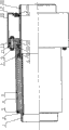
Fig. 1 absorbs structural representation before the thermal walking for the present invention;
Fig. 2 absorbs structural representation after the thermal walking for the present invention.
Description of reference numerals:
1. reducing extension tube
2. honeycomb duct
3. reducer pipe cushion cap
4. bellows
5. outer sleeve
6. cushion cap in the outer sleeve
7. the protruding outer shroud of interior pipe
8.A stuffing box packing
9. bolt and nut
10. binder flange
11. outer sleeve flange
12. steel ball
13.B stuffing box packing
14. anticorrosive casing pipe fixed beam
15. anticorrosive casing pipe
16. heat insulating washer
17. flat basic bolt
18. interior pipe
19. thermal insulation layer
Embodiment:
Below in conjunction with accompanying drawing technological scheme of the present invention is described in detail as follows.
Be illustrated in figure 1 as the structural representation before the present invention absorbs thermal walking, a kind of as can be seen from Figure novel combined compensator, the reducing extension tube 1, honeycomb duct 2, bellows 4, outer sleeve 5, anticorrosive casing pipe 15 and the interior pipe 18 that comprise the tubulose external form, external form is the circular interior cushion cap 6 of reducer pipe cushion cap 3, outer sleeve, the protruding outer shroud 7 of interior pipe, binder flange 10, outer sleeve flange 11, anticorrosive casing pipe fixed beam 14 and heat insulating washer 16, external form is the A stuffing box packing 8 and the B stuffing box packing 13 of ring-type, reaches bolt and nut 9, steel ball 12, flat basic bolt 17.(the tubulose elastic sensing element of bellows for connecting into along the folding retractable direction with collapsible wrinkle sheet.Its opening end is fixed, and sealed end is in free state, and utilizes auxiliary helical spring or reed to increase elasticity.In the elongation of the effect lower edge of internal pressure tube length direction, make movable end produce the displacement that becomes certain relation with pressure during work.Bellows mainly is divided into metal (stainless steel, carbon steel) bellows, plastic film capicitor.Metal bellows is mainly used in effects such as compensation pipes thermal distortion, damping, absorption pipeline sedimentation and deformation, is widely used in industries such as petrochemical industry, instrument, space flight, chemical industry, electric power, cement, metallurgy.Other material bellowss such as plastics have irreplaceable effect in fields such as medium transport, electric power threading, lathe, household electrical appliances.)
Described honeycomb duct 2 is a tubular structure, an end of pipe 18 in an end inserts, and the other end inserts an end of reducing extension tube 1 and is fastenedly connected with it, for example is welded to connect; The outer ring surface one extension of these reducing extension tube 1 one ports is convexly equipped with and is equipped with reducer pipe cushion cap 3, and making this reducing extension tube 1 global sections is the L type, and described reducer pipe cushion cap 3 is fastenedly connected with this outer sleeve 5.The internal diameter of the external diameter of this reducer pipe cushion cap 3 and outer sleeve 5 matches; The groove that the outer shroud of reducer pipe cushion cap 3 is provided with groove face and the corresponding setting of outer sleeve 5 inboard ends adopts to be welded to connect and makes that cushion cap 6, outer sleeve flange 11 become one structure in reducing extension tube 1, reducer pipe cushion cap 3 and outer sleeve 5, the outer sleeve.
This bellows 4 is a Collapsible structure, and is set in this honeycomb duct 2 outer ring surfaces, and these bellows 4 two-port for example are welded to connect respectively with an end contact of end of interior pipe 18 and reducing extension tube 1 and be fastenedly connected; Described outer sleeve 5 ring sets are at bellows 4 outer ring surfaces, one end and reducing extension tube 1 are fastenedly connected, manage on 18 in the other end slides over, described outer sleeve flange 11 is wholely set the end at this outer sleeve 5, these outer sleeve 5 inner ring surface one are convexly equipped with and are equipped with cushion cap 6 in the outer sleeve that the cross section is a rectangle, therefore are actually the interior cushion cap 6 of outer sleeve and slide on interior pipe 18 outer surfaces; Fastening at least one anticorrosive casing pipe fixed beam 14 that is provided with of pipe 18 outer ring surfaces in described, anticorrosive casing pipe fixed beam 14 is a ring structure, sectional shape can be rectangle or circle; These binder flange 10 ring sets are at interior pipe 18 outer ring surfaces and between this outer sleeve flange 11 and this anticorrosive casing pipe fixed beam 14; Described anticorrosive casing pipe 15 1 ends are sheathed on the outer ring surface of this outer sleeve flange 11 and binder flange 10 respectively, and the other end and anticorrosive casing pipe fixed beam 14 are fastenedly connected; Should be fastenedly connected with the protruding outer shroud 7 of interior pipe that the cross section is a rectangle by interior pipe 18 termination outer shrouds, cushion cap 6 is managed between protruding outer shroud 7 and the anticorrosive casing pipe fixed beam 14 in this in the described outer sleeve.
One end of described bellows 4 and the termination of interior pipe 18 are connected and fixed, and are actually with the termination of interior pipe 18 and the protruding outer shroud of establishing thereon 7 of interior pipe to be connected and fixed, and for example welding is fixing; Bellows 4 the other ends and reducing extension tube 1 are fastenedly connected, be actually with reducing extension tube 1 on the reducer pipe cushion cap 3 that extend to be provided be welded to connect fixing; Pipe 18, bellows 4 and anticorrosive casing pipe 15 be can coaxial synchronization-moving integrative-structure in forming respectively, and reducing extension tube 1, outer sleeve 5, the interior cushion cap 6 of outer sleeve, outer sleeve flange 11 are can coaxial synchronization-moving integrative-structure.
Described binder flange 10 is a ring-type, sectional shape is L shaped, a L shaped end contact is arranged at by the A stuffing box packing 8 in the cavity space that forms between the cushion cap 6 in outer sleeve 5 one end inboards, interior pipe 18 outer ring surfaces and the outer sleeve, L shaped other end evenly is provided with plurality of through holes, these outer sleeve flange 11 end faces evenly are provided with corresponding plurality of through holes, at least one bolt and nut 9 passes described through hole, and this outer sleeve flange 11 is linked closely with this binder flange 10 to be connected and fixed.
One end face of described A stuffing box packing 8 is withheld in outer sleeve on the cushion cap 6.
Described binder flange 10 inwardly is provided with annular groove with interior pipe 18 contact surfaces, is provided with the outer shroud of pipe 18 at least one steel ball 12 contact in the described groove.
Described outer sleeve flange 11 and binder flange 10 opposing end surfaces are respectively equipped with corresponding L type recess, and the common groove that forms of these corresponding two L type recesses is built-in with B stuffing box packing 13.
Described anticorrosive casing pipe 15 axial cross sections are the L type, and L type one end is set in the outer ring surface of binder flange 10 and outer sleeve flange 11, and are tightening state with described B stuffing box packing 13; The L type the other end and anticorrosive casing pipe fixed beam 14 are fastenedly connected by flat basic bolt 17, and described anticorrosive casing pipe fixed beam 14 contacts with anticorrosive casing pipe 15 and is provided with heat insulating washer 16 between the end face.
Described anticorrosive casing pipe 15 is coated with and rinses anticorrosive coat and constitute for glass fibre reinforced plastics polyester or composite or steel coat anticorrosive material or steel.
Figure 2 shows that the structural representation after the present invention absorbs thermal walking, the relative displacement along with the compression of bellows 4 and interior pipe 18 after the displacement can be inserted thermal insulation layer 19 in the space that outer sleeve 5 and anticorrosive casing pipe 15 are vacated.
In sum, outer sleeve 5 one ends protrude along outer ring surface and are provided with outer sleeve flange 11, and extend and be provided with cushion cap 6 in the outer sleeve that cross section is a rectangle, and the interior cushion cap 6 of outer sleeve is arranged on the inwall of this end; The other end extends with reducer pipe cushion cap 3 be fastenedly connected (such as the mode that adopts welding) by outer sleeve 5.Even distributive plural through hole on this outer sleeve flange 11; Outer ring one end face is provided with the recess of a L type.The protruding outer shroud 7 of pipe in being equipped with outside interior pipe 18 1 terminations; The outer ring surface of interior pipe 18 outer ends is provided with anticorrosive casing pipe fixed beam 14.Bellows 4 is located between outer sleeve and the honeycomb duct; The termination of one end of bellows and interior pipe 18 and the protruding outer shroud 7 of interior pipe is welded to connect fixing, and the other end and reducer pipe cushion cap 3 are welded to connect fixing.In the pipe 18, the other end inserted in the reducing extension tube 1 and is welded to connect fixing with reducing extension tube 1 in one end of honeycomb duct 2 inserted.Outer sleeve 5 is near being provided with A stuffing box packing 8 in the inboard of outer sleeve flanges 11 and the chamber between interior pipe 18 outer shrouds, and an end face of A stuffing box packing 8 is withheld in outer sleeve on the cushion cap 6, the binder end of the other end contact binder flange 10.Pipe outer ring surface and in this anticorrosion outer tube fixed beam 14 and outer sleeve between the cushion cap 6 in binder flange 10 is located at, binder flange 10 end faces are evenly distributed with through hole, at least one described bolt and nut 9 is positioned between the two and passes described through hole, and linking closely by nut is connected and fixed.The inboard of institute's binder flange 10 is provided with a groove, and groove is built-in with the outer shroud of pipe 18 in plural steel ball 12 contacts.Outer sleeve flange 11 and binder flange 10 adopt bolt and nut 9 to link closely and are connected and fixed.The end face of outer sleeve flange 11 and binder flange 10 outer rings is provided with corresponding L type recess, and the common groove that forms of corresponding two L type recesses is built-in with B stuffing box packing 13.Anticorrosive casing pipe 15 is set in the outer ring surface of binder flange 10 and outer sleeve flange 11, anticorrosive casing pipe 15 axial cross sections are the L type, one end and outer sleeve flange 11 overlap and are tightening state with B stuffing box packing 13, the other end and anticorrosive casing pipe fixed beam 14 adopt flat basic bolt 17 to be fastenedly connected, and anticorrosive casing pipe fixed beam 14 contacts with anticorrosive casing pipe 15 and is provided with heat insulating washer 16 between the end face.
Pipe forms the structure that can carry out left and right displacement synchronously with anticorrosive casing pipe of fixedlying connected with it and bellows in described.
Technological scheme of the present invention when implementing because outer sleeve 5 and reducer pipe cushion cap 3 by being welded to connect, make cushion cap 6 in outer sleeve 5 outer sleeve flanges 11, the outer sleeve, reducer pipe cushion cap 3 finally be structure as a whole with reducing extension tube 1; The protruding outer shroud 7 of pipe in place, interior pipe 18 outer shroud inner ends is provided with, the outer end of interior pipe 18 outer shrouds place is provided with anticorrosive casing pipe fixed beam 14; Be provided with bellows 4 between outer sleeve 5 and the honeycomb duct 2;
The first step is welded to connect bellows 4 and protruding outer shroud 7 of interior pipe and reducing extension tube 1 fixing earlier; Then the interior pipe 18 with interior protruding outer shroud 7 of pipe and bellows 4 is inserted in the cylindrical shell of the semi-finished product outer sleeve 5 that processes together, and manage protruding outer shroud 7 in making to cushion cap 6 to outer sleeve; Be welded to connect reducer pipe cushion cap 3 and outer sleeve 5 fixing simultaneously.
Second step embedded A stuffing box packing 8 in the outer sleeve 5 and the groove between the interior pipe 18 of outer casing flange 11 ends, make A stuffing box packing 8 interior edge faces press the end face of cushion cap 6 in the outer sleeve, in the groove of binder flange 10 inboards, place emulsus butter and steel ball 12 then, then the binder flange 10 with steel ball 12 is inserted in from interior pipe 18 outer shrouds, the binder end face that makes binder flange 10 is to the end face to A stuffing box packing 8; Then in the common groove that forms of binder flange 10 and outer sleeve flange 11 both corresponding recesses, place B stuffing box packing 13; Adopt oil hydraulic press that binder flange 10 is exerted pressure then, when pressure reaches certain grade, make the link closely end face of A stuffing box packing 8 of the binder end face of binder flange 10, make B stuffing box packing 13 also reach certain dense state simultaneously; Promptly have by the screw bolt passes outer sleeve flange in the bolt and nut 9 11 and binder flange 10 the two end face to be provided with in corresponding several hole, linking closely by the nut in the bolt and nut 9 is connected and fixed again.
The specified position of pipe 18 outer shrouds in the 3rd step was welded on anticorrosive casing pipe fixed beam 14, and put in anticorrosive casing pipe fixed beam 14 exterior edge faces and to be nested with heat insulating washer 16; Then anticorrosive casing pipe 15 is nested with the two outer shroud of outer sleeve flange 11 and binder flange 10, makes the link closely outer ring surface of B stuffing box packing 13 of ring in the long end of anticorrosive casing pipe 15L shape, make the end face on anticorrosive casing pipe 15L shape end limit be tight against anticorrosive casing pipe fixed beam 14 simultaneously; Several holes of holding the end face on limit to be provided with by anticorrosive casing pipe 15L shape adopt flat basic bolt 17 that anticorrosive casing pipe 15 and anticorrosive casing pipe fixed beam 14 are fastenedly connected then.
The 4th step is with in pipe 18 and the reducing extension tube 1 in the insertion of honeycomb duct 2; Be welded to connect honeycomb duct 2 and reducing extension tube 1 fixing simultaneously.Make honeycomb duct 2 and reducing extension tube 1 into a single integrated structure.
Carry out the metal exsertion part at last in interior corrosion resistant clad work; (comprise being coated with and rinse anticorrosive material).
This technology and structure make:
1, described steel ball 12, played interior pipe 18 and anticorrosion outer sleeve 15 has played the coaxial multi-efficiency of setting upright, reduce frictional resistance when left and right displacement.
2, described reducer pipe cushion cap 3 provides necessary condition for realization reducing extension tube 1 is identical with external diameters in the interior pipe 18; Reducing extension tube 1 is an integral body with reducer pipe cushion cap 3.
3, described reducer pipe cushion cap 3 adopts to be welded to connect with outer sleeve 5 reducing extension tube 1 and reducer pipe cushion cap 3 is become one structure with outer sleeve 5, the interior cushion cap 6 of outer sleeve, outer sleeve flange 11.
4, described A stuffing box packing 8, B stuffing box packing 13 are referred to as: fixing seals, it has anticorrosive casing pipe 15 and the good lubrication effect of interior pipe 18 when left and right displacement
5, described bellows 4, add A stuffing box packing 8 and B stuffing box packing 13 and possessed anchor ring multi-sealed in conjunction with end face; Make sealability more reliable.
6, described heat insulating washer 16 has played heat insulation, the insulation of anticorrosive casing pipe 15 and interior pipe 18, energy-conservation effect merit.
7, described anticorrosive casing pipe 15 has played the preservative efficacy real to primary structural component.
8, described anticorrosive casing pipe 15 can carry out synchronous left and right displacement with interior pipe 18;
9, antiseptic property got abundant assurance.The unfailing performance of sealing, and possess preservative efficacy, can realize the large compensation amount, enlarge Applicable scope and multi-functional characteristics; Reduce investment outlay and operating cost, really make pipeline security of operation, reliable, energy-conservation characteristics.
Claims (10)
1. a novel combined compensator is characterized in that: comprise cushion cap (6) in reducing extension tube (1), honeycomb duct (2), reducer pipe cushion cap (3), bellows (4), outer sleeve (5), the outer sleeve, the protruding outer shroud of interior pipe (7), A stuffing box packing (8), bolt and nut (9), binder flange (10), outer sleeve flange (11), steel ball (12), B stuffing box packing (13), anticorrosive casing pipe fixed beam (14), anticorrosive casing pipe (15), heat insulating washer (16), flat basic bolt (17) and interior pipe (18);
Described honeycomb duct (2) is a tubular structure, an end of pipe (18) in an end inserts, and the other end inserts an end of reducing extension tube (1) and is fastenedly connected with it; This bellows (4) is set in this honeycomb duct (2) outer ring surface, two-port respectively with an end contact of an end and the reducing extension tube (1) of interior pipe (18); Described outer sleeve (5) ring set is at bellows (4) outer ring surface, one end and reducing extension tube (1) are fastenedly connected, the other end slides on the interior pipe (18), described outer sleeve flange (11) is wholely set the end at this outer sleeve (5), and this outer sleeve (5) inner ring surface one is convexly equipped with and is equipped with cushion cap (6) in the outer sleeve that the cross section is a rectangle; Pipe (18) outer ring surface fastening at least one anticorrosive casing pipe fixed beam (14) that is provided with in described, this binder flange (10) ring set interior pipe (18) outer ring surface and be positioned at this outer sleeve flange (11) and this anticorrosive casing pipe fixed beam (14) between; Described anticorrosive casing pipe (15) one ends are sheathed on the outer ring surface of this outer sleeve flange (11) and binder flange (10) respectively, and the other end and anticorrosive casing pipe fixed beam (14) are fastenedly connected;
The termination of one end of described bellows (4) and interior pipe (18) is connected and fixed, and the other end and reducing extension tube (1) are fastenedly connected; Pipe (18), bellows (4) and anticorrosive casing pipe (15) be can coaxial synchronization-moving integrative-structure in forming respectively, and reaching reducing extension tube (1), outer sleeve (5), the interior cushion cap (6) of outer sleeve, outer sleeve flange (11) is can coaxial synchronization-moving integrative-structure.
2. compensator as claimed in claim 1, the outer ring surface one that it is characterized in that described reducing extension tube (1) one port is extended to be convexly equipped with and is equipped with reducer pipe cushion cap (3), making this reducing extension tube (1) global sections is the L type, and described reducer pipe cushion cap (3) is fastenedly connected with this outer sleeve (5).
3. compensator as claimed in claim 1, it is characterized in that described interior pipe (18) termination outer shroud is fastenedly connected with the protruding outer shroud of interior pipe (7) that the cross section is a rectangle, cushion cap (6) is positioned between this pipe protruding outer shroud (7) and the anticorrosive casing pipe fixed beam (14) in the described outer sleeve.
4. compensator as claimed in claim 1, it is characterized in that described binder flange (10) is ring-type, sectional shape is L shaped, a L shaped end contact is arranged at by the A stuffing box packing (8) in the cavity space that forms between the cushion cap (6) in outer sleeve (5) one end inboards, interior pipe (18) outer ring surface and the outer sleeve, L shaped other end evenly is provided with plurality of through holes, this outer sleeve flange (11) end face evenly is provided with corresponding plurality of through holes, at least one bolt and nut (9) passes described through hole, and this outer sleeve flange (11) and this binder flange (10) are linked closely to be connected and fixed.
5. compensator as claimed in claim 4 is characterized in that an end face of described A stuffing box packing (8) is withheld on the cushion cap in outer sleeve (6).
6. compensator as claimed in claim 1 is characterized in that described binder flange (10) and interior pipe (18) contact surface inwardly are provided with annular groove, are provided with the outer shroud of pipe (18) at least one steel ball (12) contact in the described groove.
7. as claim 1 or 4 described compensators, it is characterized in that described outer sleeve flange (11) and binder flange (10) opposing end surface are respectively equipped with corresponding L type recess, the common groove that forms of these corresponding two L type recesses is built-in with B stuffing box packing (13).
8. compensator as claimed in claim 1 is characterized in that described anticorrosive casing pipe (15) axial cross section is the L type, and L type one end is set in the outer ring surface of binder flange (10) and outer sleeve flange (11), and is tightening state with described B stuffing box packing (13); The L type the other end and anticorrosive casing pipe fixed beam (14) are fastenedly connected by flat basic bolt (17), and described anticorrosive casing pipe fixed beam (14) contacts with anticorrosive casing pipe (15) and is provided with heat insulating washer (16) between the end face.
9. compensator as claimed in claim 2 is characterized in that the external diameter of described reducer pipe cushion cap (3) and the internal diameter of outer sleeve (5) match; The groove that the outer shroud of reducer pipe cushion cap (3) is provided with groove face and the corresponding setting of the inboard end of outer sleeve (5) adopts to be welded to connect and makes that cushion cap (6), outer sleeve flange (11) become one structure in reducing extension tube (1), reducer pipe cushion cap (3) and outer sleeve (5), the outer sleeve.
10. compensator as claimed in claim 1 is characterized in that described anticorrosive casing pipe (15) is coated with and rinses anticorrosive coat and constitute for glass fibre reinforced plastics polyester or composite or steel coat anticorrosive material or steel.
Priority Applications (1)
| Application Number | Priority Date | Filing Date | Title |
|---|---|---|---|
| CN2010201093617U CN201606616U (en) | 2010-02-05 | 2010-02-05 | Novel composite compensator |
Applications Claiming Priority (1)
| Application Number | Priority Date | Filing Date | Title |
|---|---|---|---|
| CN2010201093617U CN201606616U (en) | 2010-02-05 | 2010-02-05 | Novel composite compensator |
Publications (1)
| Publication Number | Publication Date |
|---|---|
| CN201606616U true CN201606616U (en) | 2010-10-13 |
Family
ID=42951323
Family Applications (1)
| Application Number | Title | Priority Date | Filing Date |
|---|---|---|---|
| CN2010201093617U Expired - Fee Related CN201606616U (en) | 2010-02-05 | 2010-02-05 | Novel composite compensator |
Country Status (1)
| Country | Link |
|---|---|
| CN (1) | CN201606616U (en) |
Cited By (2)
| Publication number | Priority date | Publication date | Assignee | Title |
|---|---|---|---|---|
| CN102466108A (en) * | 2010-11-17 | 2012-05-23 | 陈墅庚 | Novel corrosion-resisting expansion appliance for pipelines |
| CN102654228A (en) * | 2011-03-02 | 2012-09-05 | 陈墅庚 | Novel composite type compensator for pipeline |
-
2010
- 2010-02-05 CN CN2010201093617U patent/CN201606616U/en not_active Expired - Fee Related
Cited By (3)
| Publication number | Priority date | Publication date | Assignee | Title |
|---|---|---|---|---|
| CN102466108A (en) * | 2010-11-17 | 2012-05-23 | 陈墅庚 | Novel corrosion-resisting expansion appliance for pipelines |
| CN102466108B (en) * | 2010-11-17 | 2014-04-23 | 陈墅庚 | Novel corrosion-resisting expansion appliance for pipelines |
| CN102654228A (en) * | 2011-03-02 | 2012-09-05 | 陈墅庚 | Novel composite type compensator for pipeline |
Similar Documents
| Publication | Publication Date | Title |
|---|---|---|
| CN101832443B (en) | Compound compensator for high pressure pipeline | |
| CN102359683A (en) | Plunger-type double-safety pipeline compensator | |
| CN102072363B (en) | Multi-layer single vacuum compound heat-insulation pipe | |
| CN101608726B (en) | Two-way multifunctional displacement absorption compensator | |
| CN101660646B (en) | Multifunctional displacement absorber | |
| CN204127557U (en) | Novel precise formula high pressure resistant rotary compensator | |
| CN201723898U (en) | Composite bidirectional compensator | |
| CN103968179B (en) | Novel plastic pipeline compensator | |
| CN201606616U (en) | Novel composite compensator | |
| CN103982737B (en) | Novel combined pipeline compensator | |
| CN201593664U (en) | Two-way multifunctional displacement absorption compensator | |
| CN102147037A (en) | Novel composite-type compensator | |
| CN201851831U (en) | Novel corrosion-resisting expansion device for pipeline | |
| CN102147038B (en) | Compound type bidirectional compensator | |
| CN202252489U (en) | Plunger piston type double-insurance pipeline compensator | |
| CN102466108B (en) | Novel corrosion-resisting expansion appliance for pipelines | |
| CN201715149U (en) | Large-deflection loose tube spherical compensating joint | |
| CN202484511U (en) | Plunger type multifunctional pipeline compensator | |
| CN211925116U (en) | Compound hinge type ETFE coating composite expansion joint | |
| CN201723899U (en) | Composite compensator for high-pressure pipe | |
| CN205991278U (en) | A kind of external pressure straight-pipe pressure balanced expansion joint for absorbing compound displacement | |
| CN201606614U (en) | Multifunctional displacement absorber | |
| CN201925656U (en) | Corrugated sleeve composite compensator | |
| CN208348771U (en) | A kind of fuel gas pipeline with automatic compensation function | |
| CN203770927U (en) | Novel composite type pipeline compensator |
Legal Events
| Date | Code | Title | Description |
|---|---|---|---|
| C14 | Grant of patent or utility model | ||
| GR01 | Patent grant | ||
| DD01 | Delivery of document by public notice |
Addressee: Chen Shugeng Document name: Notification to Go Through Formalities of Registration |
|
| C17 | Cessation of patent right | ||
| CF01 | Termination of patent right due to non-payment of annual fee |
Granted publication date: 20101013 Termination date: 20110205 |