CN201702267U - Composite drawing die used for punching plates - Google Patents
Composite drawing die used for punching plates Download PDFInfo
- Publication number
- CN201702267U CN201702267U CN2010202061651U CN201020206165U CN201702267U CN 201702267 U CN201702267 U CN 201702267U CN 2010202061651 U CN2010202061651 U CN 2010202061651U CN 201020206165 U CN201020206165 U CN 201020206165U CN 201702267 U CN201702267 U CN 201702267U
- Authority
- CN
- China
- Prior art keywords
- hole
- die
- stairstepping
- punching
- guide way
- Prior art date
- Legal status (The legal status is an assumption and is not a legal conclusion. Google has not performed a legal analysis and makes no representation as to the accuracy of the status listed.)
- Expired - Fee Related
Links
Images


Abstract
The utility model relates to the field of dies for metal plate punching processes, in particular to a composite drawing die used for punching plates. The composite drawing die comprises an upper die and a lower die, and is characterized in that the upper die comprises a height adjusting nut (1), a locking screw (2), a stripping compression spring (3), a shank (4), a stripping support plate (5), a tightening screw (6), a connecting screw (7), a stripping ejector rod (8), a drawing upper die (9), an upper die guider (10) which is a cylinder, a stripping ring (11) and a piercing punch (12), the lower die comprises a stripping compression spring (3), a tightening screw (6), a stripper (17), a lower die holder (18), a punching and drawing punch-die (19) and a constant-altitude sleeve (20), wherein the center of the lower die holder (18) is inserted into the punching and drawing punch-die (19). The composite drawing die is stable and reliable in processing quality and wide in applicable range.
Description
Technical field
The present invention relates to be used for metallic plate punching processed mould group field, be specially a kind of stretching composite die that is used for the sheet material punching.
Background technology
At present in metal plate punching processing, when on endoporus, doing shallow stretching or flange operation, pre-punched hole is carried out in general many employings earlier, remake the processing of shallow stretching or flange, no matter operation on common punch press or numerical control press, all need to machine through twice operation, exist that efficient is low, the problem of low precision with two molds.Especially needed intensive hole processing operation in the time of in producing for similar solar water heater, central air-conditioning radiator, the defective that the plate extension that causes during owing to pre-punched hole causes the off-centring of follow-up shallow stretching or flange not overlap, directly have influence on the crudy of workpiece, even if adopt the way of numerical control compensation also to be difficult to obtain radical cure, this defective finally causes the vertical flanges of shallow stretching or flange to be uneven, and more can cause accidents such as snap gauge, material give up, machine damage when serious.If the product category that enterprise produces is various, then need frequently more mold exchange, directly cause production efficiency to reduce and the production cost increase, in recent years along with the extensive use of numerical control press, this processing mode more can not adapt to requirement.
The utility model content
In order to overcome the defective of prior art, a kind of compactness rational in infrastructure, volume is small and exquisite, interface standard is unified, applied widely mould are provided, the utility model discloses a kind of stretching composite die that is used for the sheet material punching.
The utility model reaches goal of the invention by following technical solution:
A kind of stretching composite die that is used for the sheet material punching comprises upper mold portion and lower mold portion, and its structure is:
Upper mold portion comprises to be heightened nut, lock-screw, take off material stage clip, die shank, takes off material supporting plate, tight-hanged screw, attachment screw, takes off material push rod, stretching upper cavity die, patrix guide way, takes off material circle and piercing punch.
The patrix guide way is a cylinder, the center of patrix guide way has one from top to bottom with the stairstepping through hole of two-stage step, the aperture that the stairstepping through hole is divided into three grades and stairstepping through hole from top to bottom increases from top to bottom, die shank, take off that the material supporting plate is connected up and down by attachment screw successively with this three of patrix guide way and fixing, the center of taking off the material supporting plate has through hole, takes off the first order alignment of the central through hole and the patrix guide way stairstepping through hole of material supporting plate.
The stretching upper cavity die is fixed in the third level of patrix guide way stairstepping through hole and the upper surface of stretching upper cavity die withstands the step of stairstepping through hole, the center of stretching upper cavity die has through hole, the second level alignment of the central through hole of stretching upper cavity die and patrix guide way stairstepping through hole.
Piercing punch is a stepped cylinder, the less end of piercing punch end face passes the central through hole of stretching upper cavity die and inserts in the second level of patrix guide way stairstepping through hole and this end face withstands the step place of stairstepping through hole, passing the first order of patrix guide way stairstepping through hole with tight-hanged screw fixes the upper end of piercing punch and patrix guide way, the stretching upper cavity die, patrix guide way and this three's of piercing punch central axis overlaps mutually, the lower surface of piercing punch stretches out in outside the lower surface of stretching upper cavity die, takes off on the step that material circle is suspended on piercing punch and takes off the material circle and the two lower surface of piercing punch flushes.
Periphery at patrix guide way stairstepping through hole has 4 push-rod holes in addition, and push-rod hole evenly distributes around the stairstepping through hole, inserts in the push-rod hole and takes off the material push rod, and the lower end of taking off the material push rod is withstood and taken off the material circle and the upper end is withstood and taken off the material supporting plate; One cavity is arranged in the die shank, and the opening part of cavity covers taking off on the material supporting plate, establishes one in the cavity and takes off the material stage clip, take off the two ends of material stage clip and withstand die shank respectively and take off the material supporting plate, the top of die shank with heighten nut and fixedly connected, the side of heightening nut is connected with lock-screw.
Lower mold portion comprises takes off the material stage clip, tight-hanged screw, stripper plate, die shoe, punching stretch concavo-convex mould and Ding Gao sleeve pipe, the center of die shoe has the single order trapezoidal hole, insert the punching concavo-convex mould that stretches in the stairstepping through hole, there is a ring-like boss the stretch side of concavo-convex mould of punching, ring-like boss withstands the step of die shoe stairstepping through hole, be respectively equipped with 8 blind holes and 4 cover pipe through-holes around the stairstepping through hole, blind hole and cover pipe through-hole all center between the even distribution of stairstepping through hole and per two the adjacent bushings through holes two equally distributed blind holes are set, the opening part of blind hole upwards, be provided with in the blind hole and take off the material stage clip, cover pipe through-hole interpolation is gone into fixed high sleeve pipe, the center of stripper plate has through hole, stripper plate is placed on the die shoe and the central through hole of stripper plate is placed in punching stretches outside the concavo-convex mould, have 12 blind holes around the stripper plate central through hole, the opening part of blind hole is downward, 12 blind holes on the stripper plate, 8 blind holes and 4 the cover pipe through-holes with die shoe respectively are corresponding one by one, tight-hanged screw is with stripper plate, fixed high sleeve pipe is connected with die shoe and is fixing, takes off the two ends of material stage clip and withstands the blind hole of die shoe and the blind hole of stripper plate respectively.
The described stretching composite die that is used for the sheet material punching, its structure is: the less end of piercing punch end face passes the central through hole of stretching upper cavity die and inserts in the second level of patrix guide way stairstepping through hole and between the step place of this end face and ladder hole and is lined with compensate gasket, the center of die shoe has the single order trapezoidal hole, insert the punching concavo-convex mould that stretches in the stairstepping through hole, there is a ring-like boss the stretch side of concavo-convex mould of punching, is lined with compensate gasket between the step place of ring-like boss and die shoe stairstepping through hole.
The described stretching composite die that is used for the sheet material punching, its structure is: stretching upper cavity die, patrix guide way, piercing punch and punching stretch the surface roughness Ra value of concavo-convex mould all between 0.2~0.8.
When the utility model is practical, the patrix guide way is inserted in the top mold frame of band patrix resetting means of punch press configuration, it can accurately be moved up and down along axis; Die shoe is fixed in the following mould bases of punch press configuration, to heighten nut drops to minimum, behind definite good mold height, lock lock-screw by examination, after workpiece is transported to punching position, also the mould bases resetting-mechanism is depressed when slider of punch is depressed upper mold portion, taken off material circle and the counterdie punching workpiece that stretches under the acting in conjunction up and down of concavo-convex mould at patrix and pushed down; It is descending that slider of punch continues, and the stretching bottom outlet is gone out in the stretch edge of a knife interaction of concavo-convex mould of piercing punch and punching; It is descending that slider of punch continues, stretching upper cavity die and punching stretch the interaction of concavo-convex mould with workpiece along the even pull-up vertical flanges of bottom outlet circumference, at this moment take off the material stage clip and taken off the material push rod and expect that by taking off supporting plate jack-up compresses; The counterdie stripper plate be stretched upper cavity die depress and cause take off the material stage clip be compressed; Slider of punch is crossed after bottom dead center and is upwards returned, upper mold portion is up with slider of punch under the effect of mould bases resetting-mechanism, thereby discharging to eject to take off, the elastic force that takes off the material stage clip expects that circle ejects workpiece in stretching fovea superior die cavity, taking off material stage clip elastic force discharges counterdie stripper plate jack-up, workpiece is ejected the punching concavo-convex mould that stretches, one time punching stroke is finished, and upper mold portion and lower mold portion all return back to original state, and prepares to carry out punching stroke next time.The axial location of heightening between nut and the die shank during the utility model work is constant; Take off between material circle and the patrix guide way and leave axial tension stroke space; When piercing punch shortened because of reconditioning, available compensate gasket was got compensation discard.Die shoe is the matrix of center of turntable about accurate transfer mould bases or the numerical control press, its cylindrical and lower surface are adjacent to accurately in die shoe, leave axial tension stroke space between stripper plate and the die shoe, when punching stretches concavo-convex mould when shortening because of sharpening, same available adjustment pad is got compensation discard.
The utility model is with orderly inside that has been combined in the high accuracy guide way such as piercing punch, stretching die, hull and pulp removing machine structures, guarantee that this mould can use on the standard numerical control press, after disposing suitable mould bases on the common punch press, more can reach the purpose of quickly replacing mould.The stretch design of concavo-convex mould of piercing punch, stretching die, the punching of the utility model punching stretching composite die all adopts assembling fixed; use up or user need change machining sheet thickness the time at the edge of a knife; can change piercing punch, stretching die or the punching concavo-convex mould that stretches easily, not only economy but also convenient.The utility model critically has been combined in one with perforating die, shallow stretching die, guide way, make punch press in a punching course, finish punching and shallow stretching or flange processing and forming, avoid the drawback of processing step by step, improved the machining accuracy of working (machining) efficiency and product.
The beneficial effects of the utility model are: compactness rational in infrastructure, volume is small and exquisite, interface standard is unified, both can on common punch press, change fast and be not subjected to the influence of machine tool accuracy, can on the standard numerical control press, use again, stable processing quality is reliable, long service life, safeguard easily, can be widely used in the shaping processing of sheet material.
Description of drawings
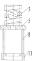
Fig. 1 is a structural representation of the present utility model;
Fig. 2 is the schematic cross-section of patrix guide way in the utility model;
Fig. 3 takes off the material stage clip, takes off the material supporting plate, takes off the material push rod and takes off the structural representation that material encloses in the utility model;
Fig. 4 is the schematic cross-section of die shoe in the utility model;
Fig. 5 is a user mode schematic diagram of the present utility model;
Fig. 6 is the structural representation of the present utility model that is added with compensate gasket;
Fig. 7 is the user mode schematic diagram of the present utility model that is added with compensate gasket.
The specific embodiment
Below further specify the utility model by specific embodiment.
Embodiment 1
A kind of stretching composite die that is used for the sheet material punching, comprise upper mold portion and lower mold portion, as shown in Figure 1, concrete structure is: upper mold portion comprises to be heightened nut 1, lock-screw 2, take off material stage clip 3, die shank 4, takes off material supporting plate 5, tight-hanged screw 6, attachment screw 7, takes off material push rod 8, stretching upper cavity die 9, patrix guide way 10, takes off material circle 11 and piercing punch 12.
Patrix guide way 10 is a cylinder, the center of patrix guide way 10 has one from top to bottom with the stairstepping through hole 101 of two-stage step, stairstepping through hole 101 is divided into three grades and aperture from top to bottom and increases from top to bottom, die shank 4, take off that material supporting plate 5 is connected up and down by attachment screw 7 successively with patrix guide way 10 these threes and fixing, the center of taking off material supporting plate 5 has through hole, takes off the first order alignment of the central through hole and the patrix guide way 10 stairstepping through holes 101 of material supporting plate 5.
Stretching upper cavity die 9 is fixed in the third level of patrix guide way 10 stairstepping through holes 101 and the upper surface of stretching upper cavity die 9 withstands the step of stairstepping through hole 101, the center of stretching upper cavity die 9 has through hole, the second level alignment of the central through hole of stretching upper cavity die 9 and patrix guide way 10 stairstepping through holes 101.
Lower mold portion comprises takes off material stage clip 3, tight-hanged screw 6, stripper plate 17, die shoe 18, punching stretch concavo-convex mould 19 and Ding Gao sleeve pipe 20, the center of die shoe 18 has single order trapezoidal hole 181, insert the punchings concavo-convex mould 19 that stretches in the stairstepping through hole 181, there is a ring-like boss the stretch side of concavo-convex mould 19 of punching, and ring-like boss withstands the step of die shoe 18 stairstepping through holes 181.As shown in Figure 4, be respectively equipped with 8 blind holes 182 and 4 cover pipe through-holes 183 around the stairstepping through hole 181, blind hole 182 and cover pipe through-hole 183 all center on stairstepping through hole 181 and evenly distribute, concrete distribution situation is: the line of 4 cover pipe through-holes 183 constitutes a square, and stairstepping through hole 181 be centered close to this foursquare center, and two equally distributed blind holes 182 are set between per two adjacent bushings through holes 183.The opening part of blind hole 182 upwards is provided with in the blind hole 182 and takes off material stage clip 3, inserts fixed high sleeve pipe 20 in the cover pipe through-hole 183.
The center of stripper plate 17 has through hole, stripper plate 17 is placed on the die shoe 18 and the central through hole of stripper plate 17 is placed in punching stretches outside the concavo-convex mould 19, have 12 blind holes around stripper plate 17 central through holes, the opening part of blind hole is downward, 12 blind holes on the stripper plate 17,8 blind holes 182 and 4 the cover pipe through-holes 183 with die shoe 18 respectively are corresponding one by one, tight-hanged screw 6 is connected stripper plate 17, fixed high sleeve pipe 20 and is fixing with die shoe 18, take off the two ends of material stage clip 3 and withstand the blind hole of die shoe 18 and the blind hole of stripper plate 17 respectively.
Stretching upper cavity die 9, patrix guide way 10, piercing punch 12 and punching stretch the surface roughness Ra value of concavo-convex mould 19 all between 0.2~0.8.
When the utility model uses, as shown in Figure 5, patrix guide way 10 is inserted in the top mold frame 13 of band patrix resetting means of punch presses configuration, it can accurately be moved up and down along axis; Die shoe 18 is fixed in the following mould bases 23 of punch press configuration, to heighten nut 1 drops to minimum, behind definite good mold height, lock lock-screw 2 by examination, after workpiece 15 is transported to punching position, also the mould bases resetting-mechanism is depressed when slider of punch is depressed upper mold portion, taken off material circle 11 and the counterdie punching workpiece 15 that stretches under the acting in conjunction up and down of concavo-convex mould 19 at patrix and pushed down; It is descending that slider of punch continues, and the stretch edge of a knife of concavo-convex mould 19 of piercing punch 12 and punching interacts and goes out the stretching bottom outlet; It is descending that slider of punch continues, stretching upper cavity die 9 and punching stretch the interaction of concavo-convex mould 19 with workpiece 15 along the even pull-up vertical flanges of bottom outlet circumference, at this moment take off material stage clip 3 and taken off material push rod 8 and compress by taking off material supporting plate 5 jack-up; Counterdie stripper plate 17 be stretched upper cavity die 9 depress and cause take off the material stage clip 3 be compressed; Slider of punch is crossed after bottom dead center and is upwards returned, upper mold portion is up with slider of punch under the effect of mould bases resetting-mechanism, thereby the elastic force that takes off material stage clip 3 discharges to eject and takes off material circle 11 workpiece 15 is ejected in stretching upper cavity die 9 chambeies, taking off material stage clip 3 elastic force discharges counterdie stripper plate 17 jack-up, workpiece 15 is ejected the punching concavo-convex mould 19 that stretches, one time punching stroke is finished, and upper mold portion and lower mold portion all return back to original state, and prepares to carry out punching stroke next time.
A kind of stretching composite die that is used for the sheet material punching comprises upper mold portion and lower mold portion, upper mold portion comprises heightens nut 1, lock-screw 2, take off material stage clip 3, die shank 4, take off material supporting plate 5, tight-hanged screw 6, attachment screw 7, take off material push rod 8, stretching upper cavity die 9, patrix guide way 10, take off material circle 11, piercing punch 12 and compensate gasket 13, lower mold portion comprises takes off material stage clip 3, tight-hanged screw 6, compensate gasket 13, stripper plate 17, die shoe 18, punching stretch concavo-convex mould 19 and Ding Gao sleeve pipe 20, as shown in Figure 6, concrete structure is: the less end of piercing punch 12 end faces passes the central through hole of stretching upper cavity die 9 and inserts in the second level of patrix guide way 10 stairstepping through holes and between the step place of this end face and ladder hole and is lined with compensate gasket 13, the center of die shoe 18 has the single order trapezoidal hole, insert the punching concavo-convex mould 19 that stretches in the stairstepping through hole, there is a ring-like boss the stretch side of concavo-convex mould 19 of punching, is lined with compensate gasket 13 between the step place of ring-like boss and die shoe 18 stairstepping through holes.Other structures are all same with embodiment 1.
When present embodiment uses, as shown in Figure 7, patrix guide way 10 is inserted in the top mold frame 13 of band patrix resetting means of punch presses configuration, die shoe 18 is fixed in the following mould bases 23 of punch press configuration, using method and embodiment 1 with.When piercing punch 12 shortened because of reconditioning, available compensate gasket 13 was got compensation discard; When punching stretches concavo-convex mould 19 when shortening because of sharpening, same available adjustment pad 13 is got compensation discard.
Claims (3)
1. a stretching composite die that is used for the sheet material punching comprises upper mold portion and lower mold portion, it is characterized in that:
Upper mold portion comprises to be heightened nut (1), lock-screw (2), take off material stage clip (3), die shank (4), takes off material supporting plate (5), tight-hanged screw (6), attachment screw (7), takes off material push rod (8), stretching upper cavity die (9), patrix guide way (10), takes off material circle (11) and piercing punch (12)
Patrix guide way (10) is cylinder; The center of patrix guide way (10) has one from top to bottom with the stairstepping through hole (101) of two-stage step; The aperture that stairstepping through hole (101) is divided into three grades and stairstepping through hole (101) from top to bottom increases from top to bottom; Die shank (4), taking off material supporting plate (5) and be connected 10 with the patrix guide way) this three connects up and down successively by attachment screw (7) and fixes; The center of taking off material supporting plate (5) has through hole; Take off the first order alignment of central through hole and patrix guide way (10) the stairstepping through hole of material supporting plate (5)
The third level upper surface interior and stretching upper cavity die (9) that stretching upper cavity die (9) is fixed on patrix guide way (10) stairstepping through hole (101) withstands the step of stairstepping through hole (101), the center of stretching upper cavity die (9) has through hole, the second level alignment of the central through hole of stretching upper cavity die (9) and patrix guide way (10) stairstepping through hole (101)
Piercing punch (12) is a stepped cylinder, the less end of piercing punch (12) end face passes the central through hole of stretching upper cavity die (9) and inserts in the second level of patrix guide way (10) stairstepping through hole (101) and this end face withstands the step place of stairstepping through hole (101), passing the first order of patrix guide way (10) stairstepping through hole (101) with tight-hanged screw (6) fixes the upper end of piercing punch (12) and patrix guide way (10), stretching upper cavity die (9), patrix guide way (10) and this three's of piercing punch (12) central axis overlaps mutually, the lower surface of piercing punch (12) stretches out in outside the lower surface of stretching upper cavity die (9), take off on the step that material circle (11) is suspended on piercing punch (12) and take off material circle (11) and the two lower surface of piercing punch (12) flushes
Periphery at patrix guide way (10) stairstepping through hole (101) has 4 push-rod holes (102) in addition, push-rod hole (102) evenly distributes around stairstepping through hole (101), insert in the push-rod hole (102) and take off material push rod (8), the lower end of taking off material push rod (8) is withstood and is taken off material circle (11) and the upper end is withstood and taken off material supporting plate (5); Die shank has a cavity in (4), the opening part of cavity covers and is taking off on the material supporting plate (5), establish one in the cavity and take off material stage clip (3), taking off the two ends of material stage clip (3) withstands die shank (4) respectively and takes off material supporting plate (5), the top of die shank (4) with heighten nut (1) and fixedly connected, the side of heightening nut (1) is connected with lock-screw (2);
Lower mold portion comprises takes off material stage clip (3), tight-hanged screw (6), stripper plate (17), die shoe (18), punching stretch concavo-convex mould (19) and fixed high sleeve pipe (20), the center of die shoe (18) has single order trapezoidal hole (181), insert the punching concavo-convex mould (19) that stretches in the stairstepping through hole (181), there is a ring-like boss the stretch side of concavo-convex mould (19) of punching, ring-like boss withstands the step of die shoe (18) stairstepping through hole (181), be respectively equipped with 8 blind holes (182) and 4 cover pipe through-holes (183) around the stairstepping through hole (181), blind hole (182) and cover pipe through-hole (183) center on all that stairstepping through hole (181) evenly distributes and per two adjacent bushings through holes (183) between two equally distributed blind holes (182) are set, the opening part of blind hole (182) upwards, be provided with in the blind hole (182) and take off material stage clip (3), insert fixed high sleeve pipe (20) in the cover pipe through-hole (183), the center of stripper plate (17) has through hole, stripper plate (17) is placed on the die shoe (18) and the central through hole of stripper plate (17) is placed in punching stretches outside the concavo-convex mould (19), have 12 blind holes around stripper plate (17) central through hole, the opening part of blind hole is downward, 12 blind holes on the stripper plate (17) respectively and 8 blind holes (182) of die shoe (18) and 4 cover pipe through-holes (183) corresponding one by one, tight-hanged screw (6) is with stripper plate (17), fixed high sleeve pipe (20) is connected with die shoe (18) and is fixing, takes off the two ends of material stage clip (3) and withstands the blind hole of die shoe (18) and the blind hole of stripper plate (17) respectively.
2. the stretching composite die that is used for the sheet material punching as claimed in claim 1, it is characterized in that: the less end of piercing punch (12) end face passes the central through hole of stretching upper cavity die (9) and inserts in the second level of patrix guide way (10) stairstepping through hole and between the step place of this end face and ladder hole and is lined with compensate gasket (13), the center of die shoe (18) has the single order trapezoidal hole, insert the punching concavo-convex mould (19) that stretches in the stairstepping through hole, there is a ring-like boss the stretch side of concavo-convex mould (19) of punching, is lined with compensate gasket (13) between the step place of ring-like boss and die shoe (18) stairstepping through hole.
3. the stretching composite die that is used for the sheet material punching as claimed in claim 1 or 2 is characterized in that: stretching upper cavity die (9), patrix guide way (10), piercing punch (12) and punching stretch the surface roughness Ra value of concavo-convex mould (19) all between 0.2~0.8.
Priority Applications (1)
| Application Number | Priority Date | Filing Date | Title |
|---|---|---|---|
| CN2010202061651U CN201702267U (en) | 2010-05-26 | 2010-05-26 | Composite drawing die used for punching plates |
Applications Claiming Priority (1)
| Application Number | Priority Date | Filing Date | Title |
|---|---|---|---|
| CN2010202061651U CN201702267U (en) | 2010-05-26 | 2010-05-26 | Composite drawing die used for punching plates |
Publications (1)
| Publication Number | Publication Date |
|---|---|
| CN201702267U true CN201702267U (en) | 2011-01-12 |
Family
ID=43439415
Family Applications (1)
| Application Number | Title | Priority Date | Filing Date |
|---|---|---|---|
| CN2010202061651U Expired - Fee Related CN201702267U (en) | 2010-05-26 | 2010-05-26 | Composite drawing die used for punching plates |
Country Status (1)
| Country | Link |
|---|---|
| CN (1) | CN201702267U (en) |
Cited By (3)
| Publication number | Priority date | Publication date | Assignee | Title |
|---|---|---|---|---|
| CN103394589A (en) * | 2013-07-02 | 2013-11-20 | 景鑫精密组件(昆山)有限公司 | Die deep-pumping forming time-delay mechanism and method |
| CN104138953A (en) * | 2014-06-23 | 2014-11-12 | 东莞市正强五金电子有限公司 | Method for manufacturing exhaust pipe for magnetron and exhaust pipe for magnetron |
| CN104438580A (en) * | 2014-11-28 | 2015-03-25 | 芜湖贝斯特新能源开发有限公司 | Punching die and punch |
-
2010
- 2010-05-26 CN CN2010202061651U patent/CN201702267U/en not_active Expired - Fee Related
Cited By (3)
| Publication number | Priority date | Publication date | Assignee | Title |
|---|---|---|---|---|
| CN103394589A (en) * | 2013-07-02 | 2013-11-20 | 景鑫精密组件(昆山)有限公司 | Die deep-pumping forming time-delay mechanism and method |
| CN104138953A (en) * | 2014-06-23 | 2014-11-12 | 东莞市正强五金电子有限公司 | Method for manufacturing exhaust pipe for magnetron and exhaust pipe for magnetron |
| CN104438580A (en) * | 2014-11-28 | 2015-03-25 | 芜湖贝斯特新能源开发有限公司 | Punching die and punch |
Similar Documents
| Publication | Publication Date | Title |
|---|---|---|
| CN201079810Y (en) | Punching flanging composite forming die for digital control turret punching machine | |
| CN108889847A (en) | A kind of spoke stamping processing composable mold | |
| CN104325015A (en) | Outer cover punching and drawing composite die | |
| CN209223021U (en) | A kind of inclined wedge both sides flange stamping die | |
| CN202779485U (en) | Punching small hole edge-scrapping composite membrane | |
| CN203304417U (en) | Flip-over type piercing and blanking die | |
| CN201702267U (en) | Composite drawing die used for punching plates | |
| CN202129366U (en) | Combination mould used for workpiece deep drawing | |
| CN202079167U (en) | Motor shell continuous mould | |
| CN209631940U (en) | A kind of stainless steel thin-wall U-shaped part deep drawn molding die | |
| CN217798429U (en) | Blanking, drawing and punching composite die and equipment using same | |
| CN204604456U (en) | A kind of die cutting die with floating location structure | |
| CN208696098U (en) | A kind of high-precision Press Tools for Automobiles | |
| CN207756725U (en) | A kind of thick material thins molding die | |
| CN105290224A (en) | Compound hardware die | |
| CN103551851A (en) | Method and die for combined forming of parts of metal plate with protrusion structure at bottom | |
| CN205309094U (en) | Whole stamping forming cold -working mould of trapezoidal gauge apron | |
| CN214108662U (en) | Special mould for forming magnetic steel blank | |
| CN209811039U (en) | Sheet metal stamping die | |
| CN201702268U (en) | Secondary flanging mold for pressure punching machine | |
| CN103658425A (en) | Material guiding structure for die of square washer | |
| CN110355274A (en) | A kind of flat-plate compressed circular arc technique and half versatility mould structure and its application method | |
| CN202803937U (en) | Novel progressive die | |
| CN101722238A (en) | Face plate die of bicycle | |
| CN105081080A (en) | Flanging forming mold |
Legal Events
| Date | Code | Title | Description |
|---|---|---|---|
| C14 | Grant of patent or utility model | ||
| GR01 | Patent grant | ||
| CF01 | Termination of patent right due to non-payment of annual fee |
Granted publication date: 20110112 Termination date: 20150526 |
|
| EXPY | Termination of patent right or utility model |