CN201687936U - Proportional depressurization mechanical sealing device - Google Patents
Proportional depressurization mechanical sealing device Download PDFInfo
- Publication number
- CN201687936U CN201687936U CN2010201838051U CN201020183805U CN201687936U CN 201687936 U CN201687936 U CN 201687936U CN 2010201838051 U CN2010201838051 U CN 2010201838051U CN 201020183805 U CN201020183805 U CN 201020183805U CN 201687936 U CN201687936 U CN 201687936U
- Authority
- CN
- China
- Prior art keywords
- chamber
- piston
- low
- pressure
- cavity
- Prior art date
- Legal status (The legal status is an assumption and is not a legal conclusion. Google has not performed a legal analysis and makes no representation as to the accuracy of the status listed.)
- Expired - Fee Related
Links
Images
Landscapes
- Structures Of Non-Positive Displacement Pumps (AREA)
Abstract
The utility model relates to a proportional depressurization mechanical sealing device comprising two or more than two mechanical seals (1a and 1b) which are connected in series axially and proportional depressurization tanks (2) that are arranged between the two mechanical seals, wherein each proportional depressurization tank (2) comprises a piston cylinder; a high pressure cavity (A) and a low pressure cavity (B) of the proportional depressurization tanks are respectively communicated with a front cavity and a rear cavity of the former stage mechanical seal through pipelines (3 and 4); medium pressure is lowered down on a certain proportion and then provided to the next stage mechanical sealing device for bearing; and the pressure proportion remains the same throughout, thus realizing the function of multistage-sealing depressurization in stages, prolonging the service life of the seals, and improving the reliability.
Description
Technical field
The utility model relates to equipment running shaft mechanical seal device.
Background technique
Continuous progress along with industrial development, the equipment that sealing load meets or exceeds 10MPa progressively increases, requirement to running shaft mechanical seal is more and more higher, single-stage machinery is sealed in so condition of high voltage operation down, not only the life-span is affected, reliability also reduces greatly, and this will directly influence the safe operation of equipment undoubtedly.
The model utility content
The purpose of this utility model provides a kind of ratio pressure reducing mechanical sealing device, adopt the method for classification step-down, promptly adopt two-stage or multi-stage mechanical to be sealed under the distribution of ratio dropping equipment segmentation and bear whole pressure, thereby reach the purpose that the single-stage sealing all moves under lower pressure, with prolonged mechanical sealing life, improve the mechanical seal operational reliability.
The utility model comprises mechanical seal that two or more axial series are arranged and the ratio step-down jar that is provided with between two mechanical seal, ratio step-down jar is by piston cylinder and the piston that is slidingly installed in piston cylinder, piston rod constitutes, piston is divided into two chambeies up and down to piston cylinder, the piston upper chamber of band piston rod is a hyperbaric chamber, hyperbaric chamber is communicated with by the ante-chamber of pipeline with first order mechanical seal, the cavity of resorption of piston is a low-pressure cavity, low-pressure cavity is communicated with by the ante-chamber of pipeline with next stage mechanical seal, i.e. the hyperbaric chamber of ratio step-down jar and low-pressure cavity are communicated with the ante-chamber and the back cavity of prime mechanical seal by pipeline respectively.
The utility model can reduce pressure medium as required according to a certain percentage, offers subordinate's mechanical seal device and bears, and this pressure proportional remains constant, thereby realizes multi-stage sealed classification buck functionality.
Its working principle is: piston lower surface is upwarded pressure by low piezodielectric in the use, and size is
 The piston upper-end surface is stressed to be made up of two-part, and one is the downward pressure of annulus area high-pressure medium, and size is
 , another is the down pressure that piston rod partly is subjected to the barometric pressure effect, size is

In the formula, D: piston cylinder diameter;
D: diameter of piston rod;
P: the pressure of hyperbaric chamber;
P; The pressure of low-pressure cavity.
Low-pressure cavity not on the leakage situation lower piston lower stress should be in state of equilibrium (piston gravity is ignored), that is:
So output low pressure
Because all use in the elevated pressures operating mode usually, so the atmospheric pressure part can be ignored, following formula can be reduced to

When having only two-stage sealing classification step-down, if wish p=0.5P, promptly
 Get d=0.7071D.Then low pressure is half of high pressure, and the pressure that two-stage sealing is born all is half of total pressure, has reduced by 50% than the pressure bearing and seal of traditional mechanical single seal and double seals and series seal, and prolonged sealing life, and reliability improves greatly.
When the low-pressure cavity medium reduces owing to seal leakage, piston can slowly move down, when piston need carry out fluid infusion to low-pressure cavity during soon near tank base, change otherwise piston is stressed during piston contact tank base, low-pressure cavity no longer provides enough pressure even pressure complete obiteration.Fluid infusion can be finished by special fluid infusion pump.
Description of drawings
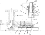
Fig. 1 is the utility model example structure schematic representation.
Embodiment
The utility model comprises the mechanical seal 1a that two or more axial series are arranged, 1b and the ratio step-down jar 2 that between two mechanical seal, is provided with, ratio step-down jar 2 is by piston cylinder 20 and the piston 22 that is slidingly installed in piston cylinder 20, piston rod 23 constitutes, piston 22 is divided into two chambeies up and down to piston cylinder 20, the piston upper chamber of band piston rod is hyperbaric chamber A, hyperbaric chamber A is communicated with the ante-chamber C of first order mechanical seal 1a by pipeline 3, the cavity of resorption of piston is low-pressure cavity B, low-pressure cavity B is communicated with the ante-chamber D of next stage mechanical seal 1b by pipeline 4, i.e. the hyperbaric chamber A of ratio step-down jar and low-pressure cavity B pass through hyperbaric chamber connecting pipe 3 respectively and be communicated with the ante-chamber and the back cavity of prime mechanical seal low-pressure cavity connecting tube 4.
Because seal face can produce a large amount of frictional heats, too high for fear of the end face temperature, the mechanical seal chamber is cooled off, be provided with cooling chamber cover 30 in ratio step-down jar 2 piston cylinders 20 outsides, chamber cover 30 interlinks with low-pressure cavity B, in cooling chamber cover 30, be provided with cooling coil 50, thereby on the rotating seat outer ring surface of secondary mechanical sealing 1b or be fixedly mounted on and offer spiral chute 61 on the ring set 6 on the rotating seat and cooperates the formation volute pump with gland 7 inner ring surfaces, cooling chamber cover 30 is communicated with by the chamber, front side of pipeline 5 with band spiral chute 61 ring sets 6 (volute pump), be communicated with low-pressure cavity connecting tube 4 and carry out the pumping circulation cooling with the rear side chamber of band spiral chute 61 ring sets 6, carry out pump circulation, realize the Seal cage heat is taken out of, reach cooling purpose.
Claims (2)
1. ratio pressure reducing mechanical sealing device, it is characterized in that, comprise the mechanical seal (1a that two or more axial series are arranged, 1b) and the ratio step-down jar (2) that between two mechanical seal, is provided with, ratio step-down jar (2) is by piston cylinder (20) and the piston (22) in piston cylinder (20) of being slidingly installed, piston rod (23) constitutes, piston (22) is divided into two chambeies up and down to piston cylinder (20), the piston upper chamber of band piston rod is hyperbaric chamber (A), hyperbaric chamber (A) is communicated with the ante-chamber (C) of first order mechanical seal (1a) by pipeline (3), the cavity of resorption of piston is low-pressure cavity (B), low-pressure cavity (B) is communicated with the ante-chamber (D) of next stage mechanical seal (1b) by pipeline (4), i.e. the hyperbaric chamber (A) of ratio step-down jar and low-pressure cavity (B) are passed through hyperbaric chamber connecting pipe (3) respectively and be communicated with the ante-chamber and the back cavity of prime mechanical seal low-pressure cavity connecting tube (4).
2. ratio pressure reducing mechanical sealing device according to claim 1, it is characterized in that, be provided with cooling chamber cover (30) in ratio step-down jar (2) piston cylinder (20) outside, chamber cover (30) interlinks with low-pressure cavity (B), in cooling chamber cover (30), be provided with cooling coil (50), on the rotating seat outer ring surface of secondary mechanical sealing (1b) or be fixedly mounted on offer spiral chute (61) on the ring set (6) on the rotating seat thus cooperates the formation volute pump with gland (7) inner ring surface, cooling chamber cover (30) is communicated with the chamber, front side of ring set (6) by pipeline (5), is communicated with the rear side chamber of ring set (6) low-pressure cavity connecting tube (4) to carry out the pumping circulation cooling.
Priority Applications (1)
| Application Number | Priority Date | Filing Date | Title |
|---|---|---|---|
| CN2010201838051U CN201687936U (en) | 2010-05-06 | 2010-05-06 | Proportional depressurization mechanical sealing device |
Applications Claiming Priority (1)
| Application Number | Priority Date | Filing Date | Title |
|---|---|---|---|
| CN2010201838051U CN201687936U (en) | 2010-05-06 | 2010-05-06 | Proportional depressurization mechanical sealing device |
Publications (1)
| Publication Number | Publication Date |
|---|---|
| CN201687936U true CN201687936U (en) | 2010-12-29 |
Family
ID=43376216
Family Applications (1)
| Application Number | Title | Priority Date | Filing Date |
|---|---|---|---|
| CN2010201838051U Expired - Fee Related CN201687936U (en) | 2010-05-06 | 2010-05-06 | Proportional depressurization mechanical sealing device |
Country Status (1)
| Country | Link |
|---|---|
| CN (1) | CN201687936U (en) |
Cited By (5)
| Publication number | Priority date | Publication date | Assignee | Title |
|---|---|---|---|---|
| CN104235052A (en) * | 2014-07-23 | 2014-12-24 | 中国航天科技集团公司第六研究院第十一研究所 | Novel pressure stabilization device for double-end surface sealing of turbine pump |
| CN104454522A (en) * | 2014-12-14 | 2015-03-25 | 张成功 | Tandem type two-stage mechanical seal device |
| CN105508618A (en) * | 2016-01-11 | 2016-04-20 | 东方电气集团东方电机有限公司 | Multilevel-redundancy main shaft seal system |
| CN110274023A (en) * | 2019-06-25 | 2019-09-24 | 杭州电子科技大学 | A kind of enclosure seal lubrication assistant boosting method |
| CN111589390A (en) * | 2020-06-02 | 2020-08-28 | 无锡职业技术学院 | Shaft seal device suitable for stirring shaft of ultrahigh pressure reaction kettle |
-
2010
- 2010-05-06 CN CN2010201838051U patent/CN201687936U/en not_active Expired - Fee Related
Cited By (8)
| Publication number | Priority date | Publication date | Assignee | Title |
|---|---|---|---|---|
| CN104235052A (en) * | 2014-07-23 | 2014-12-24 | 中国航天科技集团公司第六研究院第十一研究所 | Novel pressure stabilization device for double-end surface sealing of turbine pump |
| CN104235052B (en) * | 2014-07-23 | 2016-06-29 | 中国航天科技集团公司第六研究院第十一研究所 | A kind of turbine pump double seals stable-pressure device |
| CN104454522A (en) * | 2014-12-14 | 2015-03-25 | 张成功 | Tandem type two-stage mechanical seal device |
| CN105508618A (en) * | 2016-01-11 | 2016-04-20 | 东方电气集团东方电机有限公司 | Multilevel-redundancy main shaft seal system |
| CN105508618B (en) * | 2016-01-11 | 2017-10-13 | 东方电气集团东方电机有限公司 | A kind of spindle seal system of multilevel redundancy |
| CN110274023A (en) * | 2019-06-25 | 2019-09-24 | 杭州电子科技大学 | A kind of enclosure seal lubrication assistant boosting method |
| CN111589390A (en) * | 2020-06-02 | 2020-08-28 | 无锡职业技术学院 | Shaft seal device suitable for stirring shaft of ultrahigh pressure reaction kettle |
| CN111589390B (en) * | 2020-06-02 | 2021-10-26 | 无锡职业技术学院 | Shaft seal device suitable for stirring shaft of ultrahigh pressure reaction kettle |
Similar Documents
| Publication | Publication Date | Title |
|---|---|---|
| CN201687936U (en) | Proportional depressurization mechanical sealing device | |
| CN103790798B (en) | A kind of high-pressure pump | |
| CN203548120U (en) | System for maintaining pressure balance of diaphragm compressor | |
| CN202811571U (en) | Supercharged oil cylinder | |
| CN201196127Y (en) | Servomotor | |
| CN103671295A (en) | Closed energy storage hydraulic system | |
| CN202500761U (en) | Structure of double-stuffing box | |
| CN103759010A (en) | Packing shaft seal structure for high-pressure reciprocation pump | |
| CN107884277A (en) | A kind of multiple gas cylinder pressure test hydraulic means | |
| CN204938830U (en) | A kind of Quick lifting device of hydraulic jack | |
| CN205918549U (en) | Plunger pump | |
| CN211819901U (en) | Roots pump bypass device convenient to dismouting | |
| CN208702831U (en) | A kind of oil-returning structure at a slow speed of oil cylinder | |
| CN202971376U (en) | Oil distributing valve for novel ultra-high pressure radial piston pump | |
| CN208900338U (en) | A kind of piston type reciprocating booster pump | |
| CN103742395B (en) | A kind of design method of primary air extractor | |
| CN203394750U (en) | Novel diaphragm compressor | |
| CN201972912U (en) | Sealing structure of piston type casing gas booster pump | |
| CN202732455U (en) | Combined-type sealing structure of pump | |
| CN203939788U (en) | A kind of double-cylinder type hydraulic booster apparatus | |
| CN205423310U (en) | Novel impeller of high -efficient centrifugal pump | |
| CN202468244U (en) | Oil-free lubrication pressure regulating pump | |
| CN204357653U (en) | Secondary pressure measurement pump | |
| CN201963588U (en) | Sealing and pressure-relief device for long-shaft underwater pump | |
| CN202612024U (en) | Electric pump-supercharged water injection device |
Legal Events
| Date | Code | Title | Description |
|---|---|---|---|
| C14 | Grant of patent or utility model | ||
| GR01 | Patent grant | ||
| CF01 | Termination of patent right due to non-payment of annual fee | ||
| CF01 | Termination of patent right due to non-payment of annual fee |
Granted publication date: 20101229 Termination date: 20190506 |