CN201647145U - Packing machine - Google Patents
Packing machine Download PDFInfo
- Publication number
- CN201647145U CN201647145U CN2010201589650U CN201020158965U CN201647145U CN 201647145 U CN201647145 U CN 201647145U CN 2010201589650 U CN2010201589650 U CN 2010201589650U CN 201020158965 U CN201020158965 U CN 201020158965U CN 201647145 U CN201647145 U CN 201647145U
- Authority
- CN
- China
- Prior art keywords
- compression
- feedway
- compress
- edge banding
- packing
- Prior art date
- Legal status (The legal status is an assumption and is not a legal conclusion. Google has not performed a legal analysis and makes no representation as to the accuracy of the status listed.)
- Expired - Fee Related
Links
Images


Abstract
The utility model relates to the packing field of puffy textiles and discloses a packing machine. The packing machine comprises a material compression device and a packing edge banding device that are adjacent front and back, wherein the material compression device is provided with an upper compression support; the upper compression support is connected with an upper compression cylinder and an upper pressing conveying appliance provided with an upper compression conveying belt; the material compression device is also provided with a lower compression support that is connected with a lower pressing conveying device provided with a lower compression conveying belt; the upper and lower pressing conveying devices are separated with a compression space in between; the packing edge banding device comprises a packaging film locating device, a sealing device, an edge banding conveying device and an edge banding device that are all provided with two upper and lower corresponding structures; the packaging film locating device, the sealing device and the edge banding conveying device are sequentially closely adjacent to the compression space; the edge banding device is closely adjacent to the other two sides of the edge banding conveying device other than upper, lower, front and rear sides; and the sectional shapes of the two upper and lower corresponding structures are centrosymmetrical and separated with an encapsulation space in between. The packing machine saves packaging material and is extremely economical, practical.
Description
Technical field
The utility model relates to fluffy core class textile package field, relates in particular to a kind of compress.
Background technology
At present, fluffy core class textiles all adopts inhales the packing that contracts, though this method also can be dwindled the volume of these class article, but packaging film is the size of packaging article under fluffy state, the waste packing, production efficiency is low, and inhales the back product shrinkage of contracting, and has a strong impact on the attractive in appearance and product design of product.
The utility model content
In view of this, technical problem to be solved in the utility model is: provide a kind of simple in structure, the compress that economizes on resources and can obviously increase work efficiency.
In order to achieve the above object, the utility model adopts following technical scheme to realize:
A kind of compress, wherein, comprise material compression set and packing edge banding apparatus that front and back are adjacent, described material compression set has last compressed stent, described go up compressed stent be connected with in order to conduction press down the last compressor cylinder of power and have go up compress load-transfer device on compress feedway, described material compression set also has the lower compression support, described lower compression support is connected with the following feedway that compresses with lower compression load-transfer device, compress feedway on described and compress down feedway corresponding up and down and between be partitioned into compression space in order to the placement material, described packing edge banding apparatus comprises all having the packaging film registration device of corresponding two-part structure up and down, closing device, edge sealing feedway and edge banding apparatus with compression load-transfer device, described packaging film registration device, closing device and edge sealing feedway are close to described compression space successively, described edge banding apparatus is close to the other both sides of described edge sealing feedway before and after being different from up and down, the cross sectional shape center symmetry of described corresponding two-part structure up and down and between be partitioned into encapsulated space in order to packing materials.
As preferably, the superposed structure of described closing device comprises the mobile roller that is positioned between described packaging film registration device and edge sealing feedway, the top of described mobile roller is provided with in order to the following closing device of pressure seal mouth, is connected with on the described mobile roller in order to conduction power described mobile roller is mentioned or the movable cylinder of homing to described edge sealing feedway one side.
As preferably, described edge sealing feedway is positioned at the structure of bottom in being longer than the superposed structure of described edge sealing feedway away from described material compression set one side.
As preferably, described lower compression support lower end is connected with the lower compression cylinder in order to conduction rising power.
As preferably, described compress also is provided with the PLC process controller, and described material compression set and packing edge banding apparatus all are electrically connected on described PLC process controller.
As shown from the above technical solution, the beneficial effects of the utility model are:
Compared to existing technology; the utility model is simple in structure; economical and practical; the degree of automation height; by setting to material compression set and packing edge banding apparatus; adopt compression earlier; wrap packaging film by the transmission of compression load-transfer device and edge sealing load-transfer device again; cut off behind the across seal then; carry out the mode of edge sealing at last in the outside, both sides of edge sealing load-transfer device, make it both save packing, protected the outward appearance of product again; also can obviously increase work efficiency, save traffic cost, be the compress of ideal fluffy core class textiles.
Description of drawings
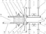
Fig. 1 is the utility model working state schematic representation one, has wherein illustrated thing to be compressed is put in the state of preparing compression in the compression zone.
Fig. 2 is the utility model working state schematic representation two, has wherein illustrated the state that the state after compression is finished is sealing.
Fig. 3 is the utility model working state schematic representation three, has wherein illustrated the state that edge sealing is prepared in the back that seals of finishing.
Fig. 4 is the working state schematic representation of the utility model packing edge banding apparatus, illustrated that wherein both sides are just at the state of edge sealing.
The specific embodiment
In order to make those skilled in the art can further understand feature of the present utility model and technology contents, see also following about detailed description of the present utility model and accompanying drawing.
See also Fig. 1 to shown in Figure 4, the utility model provides a kind of compress, wherein, comprise material 7 compression sets and packing edge banding apparatus that front and back are adjacent, described material 7 compression sets have last compressed stent 3, described go up compressed stent 3 upper ends be connected with in order to conduction press down the last compressor cylinder 1 of power and have go up compress load-transfer device 5 on compress feedway, described material 7 compression sets also have lower compression support 4, described lower compression support 4 is connected with the following feedway that compresses with lower compression load-transfer device 6, compress feedway on described and compress down feedway corresponding up and down and between be partitioned into compression space 19 in order to placement material 7, described packing edge banding apparatus comprises all having the packaging film registration device 21 of corresponding two-part structure up and down, closing device, edge sealing feedway and edge banding apparatus with compression load-transfer device, described packaging film registration device, closing device and edge sealing feedway are close to described compression space 19 successively, described edge banding apparatus is close to described edge sealing feedway and is different from the other both sides of front and back up and down, the cross sectional shape center symmetry of described up and down corresponding two-part structure and between be partitioned into encapsulated space 20 in order to packing materials 7, the superposed structure of described closing device comprises the mobile roller that is positioned between described packaging film registration device and edge sealing feedway, the superposed structure of described mobile roller comprises mobile roller 11, the structure that described mobile roller is positioned at the bottom comprises and moves down action roller 12, described top of mobile roller 11 is provided with the last closing device 13 in order to following pressure seal mouth, the below that moves down action roller 12 is provided with the lower sealing device 14 that seals in order to rising, being connected with on the described mobile roller in order to conduction power makes described mobile roller mention or the movable cylinder of homing to described edge sealing feedway one side, the superposed structure of described movable cylinder comprises movable cylinder 9, the structure that described movable cylinder is positioned at the bottom comprises movable cylinder 10 down, the superposed structure of described edge banding apparatus comprises edge banding apparatus 15, the structure that described edge banding apparatus is positioned at the bottom comprises lower sealing edge device 16, described edge sealing feedway is positioned at the structure of bottom in being longer than the superposed structure of described edge sealing feedway away from described material 7 compression sets one side, and described lower compression support 4 lower ends are connected with the lower compression cylinder 2 in order to conduction rising power.Described edge sealing feedway comprise in the described up and down edge banding apparatus in order to constitute the edge sealing district and the last edge sealing load-transfer device 17 and the lower sealing edge load-transfer device 18 of transmitting power be provided.
Specifically, in actual applications, the utility model is mainly used in the compressed articles (material 7) that fluffy core class is folded into certain length and width shape, be laminated to certain height (as shown in Figure 1) again, last compressor cylinder 1 one ends are fixed on the frame, the other end is connected on the compressed stent 3, lower compression cylinder 2 one ends are fixed on the frame, the other end is connected on the compressed stent 4, last compression load-transfer device 5 is connected on the compressed stent 3, lower compression load-transfer device 6 is connected on the lower compression support 4, but being compressed to certain altitude on compression load-transfer device 5 and the lower compression load-transfer device 6 in the transmission, be fed forward on the last edge sealing load-transfer device 17 and lower sealing edge load-transfer device 18 of same height, simultaneously along with PE film 8 on the bull ladle, last compressor cylinder 1 and lower compression cylinder 2 return, and wait for that second working cycle put constrictor and continue compression.Go up simultaneously movable cylinder 9 and the upward mobile roller 11 of following movable cylinder 10 drives and move down action roller 12 and return (as shown in Figure 2), last movable cylinder 9 one ends are fixed on the frame, the other end is connected on the mobile roller 11, following movable cylinder 10 1 ends also are fixed on the frame, the other end is connected and moves down on the action roller 12, last closing device 13 is fixed on the frame, lower sealing device 14 also is fixed on the frame, last closing device 13 forms an enclosed mechanism with lower sealing device 14, go up closing device 13 between two load-transfer devices and move simultaneously, begin to seal with lower sealing device 14.After PE film 8 is sealed, cut off (as shown in Figure 2), last closing device 13 and lower sealing device 14 return.At this moment go up edge sealing load-transfer device 17 and lower sealing edge load-transfer device 18 and move forward certain distance (as shown in Figure 3), after begin both sides and seal, last edge banding apparatus 15 and lower sealing edge device 16 move edge sealing (as shown in Figure 4) simultaneously, last edge banding apparatus 15 forms an edge sealing mechanism with lower sealing edge device 16, return after sealing, go up simultaneously movable cylinder 9 and the upward mobile roller 11 of following movable cylinder 10 drives and move down action roller 12 and reset, at this moment, last edge sealing load-transfer device 17 and lower sealing edge load-transfer device 18 move forward again, enter back one automatic operation.
But the above only is a preferable possible embodiments of the present utility model, is not in order to limit to claim of the present utility model, so the equivalent structure that all utilization the utility model specification sheetss and accompanying drawing content are done changes, all in like manner to be included in the scope of the present utility model.
Claims (5)
1. compress, it is characterized in that, comprise material compression set and packing edge banding apparatus that front and back are adjacent, described material compression set has last compressed stent, described go up compressed stent be connected with in order to conduction press down the last compressor cylinder of power and have go up compress load-transfer device on compress feedway, described material compression set also has the lower compression support, described lower compression support is connected with the following feedway that compresses with lower compression load-transfer device, compress feedway on described and compress down feedway corresponding up and down and between be partitioned into compression space in order to the placement material, described packing edge banding apparatus comprises all having the packaging film registration device of corresponding two-part structure up and down, closing device, edge sealing feedway and edge banding apparatus with compression load-transfer device, described packaging film registration device, closing device and edge sealing feedway are close to described compression space successively, described edge banding apparatus is close to the other both sides of described edge sealing feedway before and after being different from up and down, the cross sectional shape center symmetry of described corresponding two-part structure up and down and between be partitioned into encapsulated space in order to packing materials.
2. compress as claimed in claim 1, it is characterized in that, the superposed structure of described closing device comprises the mobile roller that is positioned between described packaging film registration device and edge sealing feedway, the top of described mobile roller is provided with in order to the following closing device of pressure seal mouth, is connected with on the described mobile roller in order to conduction power described mobile roller is mentioned or the movable cylinder of homing to described edge sealing feedway one side.
3. compress as claimed in claim 2 is characterized in that, described edge sealing feedway is positioned at the structure of bottom in being longer than the superposed structure of described edge sealing feedway away from described material compression set one side.
4. as each described compress in the claim 1 to 3, it is characterized in that described lower compression support lower end is connected with the lower compression cylinder in order to conduction rising power.
5. compress as claimed in claim 4 is characterized in that described compress also is provided with the PLC process controller, and described material compression set and packing edge banding apparatus all are electrically connected on described PLC process controller.
Priority Applications (1)
| Application Number | Priority Date | Filing Date | Title |
|---|---|---|---|
| CN2010201589650U CN201647145U (en) | 2010-04-15 | 2010-04-15 | Packing machine |
Applications Claiming Priority (1)
| Application Number | Priority Date | Filing Date | Title |
|---|---|---|---|
| CN2010201589650U CN201647145U (en) | 2010-04-15 | 2010-04-15 | Packing machine |
Publications (1)
| Publication Number | Publication Date |
|---|---|
| CN201647145U true CN201647145U (en) | 2010-11-24 |
Family
ID=43112373
Family Applications (1)
| Application Number | Title | Priority Date | Filing Date |
|---|---|---|---|
| CN2010201589650U Expired - Fee Related CN201647145U (en) | 2010-04-15 | 2010-04-15 | Packing machine |
Country Status (1)
| Country | Link |
|---|---|
| CN (1) | CN201647145U (en) |
Cited By (11)
| Publication number | Priority date | Publication date | Assignee | Title |
|---|---|---|---|---|
| CN102642631A (en) * | 2012-04-26 | 2012-08-22 | 南通通用机械制造有限公司 | Three-dimensional film packing machine |
| CN104260945A (en) * | 2014-09-15 | 2015-01-07 | 金华洁灵家居用品有限公司 | Pneumatic sealing all-in-one machine |
| CN104843240A (en) * | 2015-04-10 | 2015-08-19 | 南通通机股份有限公司 | Transverse seal heating cutter device and manipulation method thereof |
| CN107839925A (en) * | 2013-03-26 | 2018-03-27 | 奥特发德国科技有限公司 | Packing device and packing method and baling press |
| CN110356812A (en) * | 2018-04-09 | 2019-10-22 | 浙江华剑智能装备有限公司 | Spring packs conveying device, spring conveying equipment and spring manufacturing equipment |
| CN110356631A (en) * | 2018-04-09 | 2019-10-22 | 浙江华剑智能装备有限公司 | Spring packs conveying device, spring conveying equipment and spring manufacturing equipment |
| CN110356628A (en) * | 2018-04-09 | 2019-10-22 | 浙江华剑智能装备有限公司 | Spring packs conveying device, spring conveying equipment and spring manufacturing equipment |
| CN110356629A (en) * | 2018-04-09 | 2019-10-22 | 浙江华剑智能装备有限公司 | Spring packs conveying device, spring conveying equipment and spring manufacturing equipment |
| CN110356630A (en) * | 2018-04-09 | 2019-10-22 | 浙江华剑智能装备有限公司 | Spring packs delivery method |
| CN110356627A (en) * | 2018-04-09 | 2019-10-22 | 浙江华剑智能装备有限公司 | Spring packs conveying device, spring conveying equipment and spring manufacturing equipment |
| CN110831862A (en) * | 2017-08-09 | 2020-02-21 | 奥特发德国科技有限公司 | Packaging apparatus and packaging method |
-
2010
- 2010-04-15 CN CN2010201589650U patent/CN201647145U/en not_active Expired - Fee Related
Cited By (13)
| Publication number | Priority date | Publication date | Assignee | Title |
|---|---|---|---|---|
| CN102642631A (en) * | 2012-04-26 | 2012-08-22 | 南通通用机械制造有限公司 | Three-dimensional film packing machine |
| CN107839925A (en) * | 2013-03-26 | 2018-03-27 | 奥特发德国科技有限公司 | Packing device and packing method and baling press |
| CN104260945A (en) * | 2014-09-15 | 2015-01-07 | 金华洁灵家居用品有限公司 | Pneumatic sealing all-in-one machine |
| CN104843240A (en) * | 2015-04-10 | 2015-08-19 | 南通通机股份有限公司 | Transverse seal heating cutter device and manipulation method thereof |
| CN110831862A (en) * | 2017-08-09 | 2020-02-21 | 奥特发德国科技有限公司 | Packaging apparatus and packaging method |
| CN110356628A (en) * | 2018-04-09 | 2019-10-22 | 浙江华剑智能装备有限公司 | Spring packs conveying device, spring conveying equipment and spring manufacturing equipment |
| CN110356631A (en) * | 2018-04-09 | 2019-10-22 | 浙江华剑智能装备有限公司 | Spring packs conveying device, spring conveying equipment and spring manufacturing equipment |
| CN110356629A (en) * | 2018-04-09 | 2019-10-22 | 浙江华剑智能装备有限公司 | Spring packs conveying device, spring conveying equipment and spring manufacturing equipment |
| CN110356630A (en) * | 2018-04-09 | 2019-10-22 | 浙江华剑智能装备有限公司 | Spring packs delivery method |
| CN110356627A (en) * | 2018-04-09 | 2019-10-22 | 浙江华剑智能装备有限公司 | Spring packs conveying device, spring conveying equipment and spring manufacturing equipment |
| CN110356812A (en) * | 2018-04-09 | 2019-10-22 | 浙江华剑智能装备有限公司 | Spring packs conveying device, spring conveying equipment and spring manufacturing equipment |
| CN110356812B (en) * | 2018-04-09 | 2022-11-25 | 浙江华剑智能装备股份有限公司 | Spring bagging conveying device, spring conveying equipment and spring manufacturing equipment |
| CN110356631B (en) * | 2018-04-09 | 2022-11-25 | 浙江华剑智能装备股份有限公司 | Spring bagging and conveying device, spring conveying equipment and spring manufacturing equipment |
Similar Documents
| Publication | Publication Date | Title |
|---|---|---|
| CN201647145U (en) | Packing machine | |
| CN203937883U (en) | A kind of tea packaging machine | |
| CN105083607A (en) | Tea packing machine | |
| CN201864062U (en) | Full-automatic vacuum package machine | |
| CN207417292U (en) | A kind of packaging bag enclosing, cutting integrated apparatus | |
| CN202846955U (en) | Heat-seal bag machine for manufacturing square bottom plastic bag | |
| CN203047557U (en) | Automatic packing machine | |
| CN103786926A (en) | Semi-automatic chopstick packaging device | |
| CN202244204U (en) | Filling seal device for preformed bag packaging machine | |
| CN103407607B (en) | Multiplexly adjustablely vacuumize heat-sealing bagging apparatus without chamber | |
| CN202765322U (en) | Industrial explosive small cartridge packing device | |
| CN104176319A (en) | Automatic packaging machine employing raw PE (polyethylene) film of zip-lock bags | |
| CN103523267A (en) | Method and equipment for packaging and weighing of tobacco in post processing | |
| CN205240863U (en) | Automatic change tealeaves packagine machine | |
| CN201686025U (en) | Crawler-type thermoplastic blister packaging machine | |
| CN203392024U (en) | Multi-purpose adjustable no-chamber vacuumization heat-sealing packaging device | |
| CN202828114U (en) | Double-station vacuum seal system for shaping vacuum packaging machine | |
| CN206273691U (en) | A kind of package sealing machine | |
| CN204587391U (en) | A kind of vacuum packaging equipment that can regulate | |
| CN203567984U (en) | Vacuum package machine for fluffy filaments | |
| CN203467644U (en) | Tobacco packaging machine | |
| CN204056408U (en) | The former film automatic packaging machine of PE sealing bag | |
| CN203601642U (en) | Novel adhesive tape box packaging mechanism | |
| CN203419316U (en) | Sealing and conveying mechanism of packaging machine | |
| CN201770032U (en) | Full-automatic vertical vacuum packaging machine |
Legal Events
| Date | Code | Title | Description |
|---|---|---|---|
| C14 | Grant of patent or utility model | ||
| GR01 | Patent grant | ||
| C17 | Cessation of patent right | ||
| CF01 | Termination of patent right due to non-payment of annual fee |
Granted publication date: 20101124 Termination date: 20130415 |