CN201645107U - Front fork assembly fixture for scooter - Google Patents
Front fork assembly fixture for scooter Download PDFInfo
- Publication number
- CN201645107U CN201645107U CN 201020129281 CN201020129281U CN201645107U CN 201645107 U CN201645107 U CN 201645107U CN 201020129281 CN201020129281 CN 201020129281 CN 201020129281 U CN201020129281 U CN 201020129281U CN 201645107 U CN201645107 U CN 201645107U
- Authority
- CN
- China
- Prior art keywords
- front fork
- pair
- holder
- fixing
- contact pin
- Prior art date
- Legal status (The legal status is an assumption and is not a legal conclusion. Google has not performed a legal analysis and makes no representation as to the accuracy of the status listed.)
- Expired - Fee Related
Links
Images


Landscapes
- Forklifts And Lifting Vehicles (AREA)
Abstract
The utility model provides a front fork assembly fixture for a scooter, which comprises a first clamping mechanism for fixing a front fork vertical pipe, a second clamping mechanism for fixing a pair of front fork leg pipes, and a third clamping mechanism for fixing a pair of front fork connecting sheets. The first clamping mechanism comprises a vertical pipe fixing seat and a first clamping cylinder capable of fixing the front fork vertical pipe on the vertical pipe fixing seat in a compacted manner; the second clamping mechanism comprises a pair of leg pipe fixing seats corresponding to the pair of front fork leg pipes, and a pair of second clamping cylinders capable of respectively fixing the pair of front fork leg pipes on the pair of leg pipe fixing seats in a compacted manner; the third clamping mechanism comprises a connecting sheet fixing seat, and a pair of third clamping cylinders capable of respectively fixing the tail parts of the pair of front fork connecting sheets at the two sides of the connecting sheet fixing seat in a compacted manner; the connecting sheet fixing seat and the pair of leg pipe fixing seats are correspondingly arranged, the third clamping mechanism is arranged on a sliding fixing seat, and the sliding fixing seat can control and drive the pair of front fork connecting sheets to approach the pair of front fork leg pipes by a sliding mechanism. The front fork assembly fixture is convenient for welding and fixing the front fork vertical pipe, the pair of front fork leg pipes and the pair of front fork connecting sheets.
Description
Technical field
The utility model relates to pipe fitting welding fixed jig, vertical tube of front fork, fork blade pipe and front fork contact pin welding fixed jig on particularly a kind of scooter.
Background technology
As shown in Figure 1, the front fork assembly of scooter is by vertical tube of front fork 1, a pair of fork blade pipe 21,22 and be welded in this a pair of front fork contact pin 31,32 to fork blade pipe 21,22 respectively and form, this inserts fixing hole corresponding on this vertical tube of front fork end respectively to fork blade pipe top, this is fixed fixing hole on fork blade pipe 21,22 tops and this vertical tube of front fork end on the one hand, on the other hand this is individually fixed in this to the fork blade tube end to front fork contact pin 31,32, welding has respectively formed this front fork assembly then.In the prior art, weld the loaded down with trivial details vertical tube of front fork of such complexity, a pair of fork blade pipe and a pair of front fork contact pin needs a lot of procedures to finish, and efficient is low, and uniformity is poor.
Summary of the invention
In order to remedy above deficiency, the utility model provides a kind of scooter front fork assembly tool, is convenient to vertical tube of front fork, a pair of fork blade pipe and a pair of front fork contact pin welding fixing.
Technology side of the present utility model is such realization: a kind of scooter front fork assembly tool, comprise first clamp mechanism of fixing vertical tube of front fork, second clamp mechanism of fixing a pair of fork blade pipe, and also comprise the 3rd clamp mechanism of fixing a pair of front fork contact pin, wherein:
1) this first clamp mechanism comprises the standpipe holder and this vertical tube of front fork is fixed first clamping cylinder in this standpipe holder;
2) this second clamp mechanism comprises should and respectively this being fixed in this a pair of second clamping cylinder to leg pipe holder the fork blade pipe the pair of leg pipe holder of fork blade pipe;
3) the 3rd clamp mechanism comprises the contact pin holder and can be respectively this be fixed a pair of the 3rd clamping cylinder in these contact pin holder both sides to front fork contact pin afterbody, this contact pin holder with this to the corresponding setting of leg pipe holder, the 3rd clamp mechanism is located on the slip holder, this slip holder can by slide mechanism control related this contact pin relies on this to the fork blade pipe to front fork.
Further improve as the utility model, this slide mechanism is the drive rod that an end is fixed this slip holder, this drive rod other end is connected with the quick detach assembly of being made up of quadric chain, and should be subjected to this drive rod and the control of quick detach assembly leg pipe holder to be slided fixing along this by the slip holder.
Further improve as the utility model, this drive rod middle part wears a compression spring, and this quick detach assembly drives this by this compression spring front fork contact pin is adjacent to this all the time to the fork blade pipe.
Useful technique effect of the present utility model is: described first clamp mechanism is used for fixing vertical tube of front fork, described second clamp mechanism is used to be fixedly clamped this to the fork blade pipe, and the 3rd clamp mechanism is used for fixing this to front fork contact pin, because the 3rd clamp mechanism is installed on the slip holder, so the 3rd clamp mechanism can be controlled this by this slide mechanism, and contact pin relies on this to the fork blade pipe to front fork, installation and removal are convenient like this, safety.
Description of drawings
Fig. 1 is for using the structural representation of the utility model welding back front fork assembly;
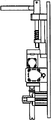
Fig. 2 is a structural front view of the present utility model;
Fig. 3 is a structure vertical view of the present utility model;
Fig. 4 is a structural perspective of the present utility model.
Below accompanying drawing is remarked additionally:
1-vertical tube of front fork 21, a pair of fork blade pipe of 22-
31, a pair of front fork contact pin 53 of 32-, a pair of second clamping cylinder of 54-
41-standpipe holder 61-contact pin holder
42-first clamping cylinder 62, a pair of the 3rd clamping cylinder of 63-
51,52-pair of leg pipe holder
64-slip holder 67-compresses spring
65-drive rod 66-quick detach assembly
The specific embodiment
A kind of scooter front fork assembly tool comprises first clamp mechanism of fixing vertical tube of front fork 1, second clamp mechanism of fixing a pair of fork blade pipe 21,22, also comprises the 3rd clamp mechanism of fixing a pair of front fork contact pin 31,32, wherein:
1) this first clamp mechanism comprises standpipe holder 41 and this vertical tube of front fork 1 is fixed first clamping cylinder 42 in this standpipe holder 41;
2) this second clamp mechanism comprises should and respectively this being fixed in this a pair of second clamping cylinder 53,54 to leg pipe holder 51,52 fork blade pipe 21,22 the pair of leg pipe holder 51,52 of fork blade pipe 21,22;
3) the 3rd clamp mechanism comprise contact pin holder 61 and can be respectively with this to front fork contact pin 31,32 afterbodys are fixed a pair of the 3rd clamping cylinder 62 in these contact pin holder 61 both sides, 63, this contact pin holder 61 with this to leg pipe holder 51,52 corresponding settings, the 3rd clamp mechanism is located on the slip holder 64, this slip holder 64 can by slide mechanism control related this to front fork contact pin 31,32 rely on this to fork blade pipe 21,22, this slide mechanism is the drive rod 65 that an end is fixed this slip holder 64, these drive rod 65 other ends are connected with the quick detach assembly of being made up of quadric chain 66, and should control along this leg pipe holder 51 by this drive rod 65 and quick detach assembly 66 by slip holder 64,52 slide fixes, these drive rod 65 middle parts wear a compression spring 67, this quick detach assembly 66 drives this to front fork contact pin 31 by this compression spring 67,32 are adjacent to this all the time to fork blade pipe 21,22, this to front fork contact pin be adjacent to all the time this to the fork blade pipe after, could weld.
Above-mentioned quick detach tong adopts the quick detach group of being made up of quadric chain, belongs to prior art, and the technical staff is easy to obtain in the industry, is not described in detail at this.
Use operation of the present utility model to be:
1) utilizes this first clamp mechanism this vertical tube of front fork 1 that is fixedly clamped, after then this being inserted corresponding fixing hole on this vertical tube of front fork 1 end respectively to fork blade pipe 21,22 tops, utilize this second clamp mechanism to fix this fork blade pipe 21,22 is fixedly clamped, utilize the 3rd clamp mechanism to fix this again front fork contact pin 31,32;
2) start first, second and the 3rd clamping cylinder respectively, vertical tube of front fork, fork blade pipe and front fork contact pin are fixedly clamped, utilize this quick detach assembly 66 then, by drive rod 65 and slip holder 64 drive the 3rd clamp mechanism with this to front fork contact pin 31,32 by last this to fork blade pipe 21,22, finish being fixedly clamped before the welding thus.
Claims (3)
1. scooter front fork assembly tool, it is characterized in that, comprise first clamp mechanism of fixing vertical tube of front fork (1), second clamp mechanism of fixing a pair of fork blade pipe (21,22), also comprise the 3rd clamp mechanism of fixing a pair of front fork contact pin (31,32), wherein:
1) this first clamp mechanism comprises standpipe holder (41) and this vertical tube of front fork (1) is fixed first clamping cylinder (42) in this standpipe holder (41);
2) this second clamp mechanism comprises should and respectively this being fixed in this a pair of second clamping cylinder (53,54) to leg pipe holder (51,52) fork blade pipe (21,22) the pair of leg pipe holder (51,52) of fork blade pipe (21,22);
3) the 3rd clamp mechanism comprises contact pin holder (61) and can be respectively this be fixed a pair of the 3rd clamping cylinder (62,63) in this contact pin holder (61) both sides to front fork contact pin (31,32) afterbody, this contact pin holder (61) with this to the corresponding setting of leg pipe holder (51,52), the 3rd clamp mechanism is located on the slip holder (64), and this slip holder (64) can be controlled related this by slide mechanism front fork contact pin (31,32) is relied on this to fork blade pipe (21,22).
2. a kind of scooter front fork assembly tool as claimed in claim 1, it is characterized in that, this slide mechanism is the drive rod (65) that an end is fixed this slip holder (64), this drive rod (65) other end is connected with the quick detach assembly of being made up of quadric chain (66), and should be subjected to this drive rod (65) and quick detach assembly (66) control leg pipe holder (51,52) to be slided fixing along this by slip holder (64).
3. a kind of scooter front fork assembly tool as claimed in claim 2, it is characterized in that, this drive rod (65) middle part wears a compression spring (67), and this quick detach assembly (66) drives this by this compression spring (67) front fork contact pin (31,32) is adjacent to this all the time to fork blade pipe (21,22).
Priority Applications (1)
| Application Number | Priority Date | Filing Date | Title |
|---|---|---|---|
| CN 201020129281 CN201645107U (en) | 2010-03-04 | 2010-03-04 | Front fork assembly fixture for scooter |
Applications Claiming Priority (1)
| Application Number | Priority Date | Filing Date | Title |
|---|---|---|---|
| CN 201020129281 CN201645107U (en) | 2010-03-04 | 2010-03-04 | Front fork assembly fixture for scooter |
Publications (1)
| Publication Number | Publication Date |
|---|---|
| CN201645107U true CN201645107U (en) | 2010-11-24 |
Family
ID=43110313
Family Applications (1)
| Application Number | Title | Priority Date | Filing Date |
|---|---|---|---|
| CN 201020129281 Expired - Fee Related CN201645107U (en) | 2010-03-04 | 2010-03-04 | Front fork assembly fixture for scooter |
Country Status (1)
| Country | Link |
|---|---|
| CN (1) | CN201645107U (en) |
Cited By (1)
| Publication number | Priority date | Publication date | Assignee | Title |
|---|---|---|---|---|
| CN105620587A (en) * | 2016-03-21 | 2016-06-01 | 南京大盛汽车部件有限公司 | Pipe fitting headrest structure mounting fixture |
-
2010
- 2010-03-04 CN CN 201020129281 patent/CN201645107U/en not_active Expired - Fee Related
Cited By (2)
| Publication number | Priority date | Publication date | Assignee | Title |
|---|---|---|---|---|
| CN105620587A (en) * | 2016-03-21 | 2016-06-01 | 南京大盛汽车部件有限公司 | Pipe fitting headrest structure mounting fixture |
| CN105620587B (en) * | 2016-03-21 | 2018-01-09 | 南京大盛汽车部件有限公司 | Pipe fitting headrest structure mounting fixture |
Similar Documents
| Publication | Publication Date | Title |
|---|---|---|
| CN203712018U (en) | Clamping device for large agricultural machinery gears | |
| CN204818687U (en) | Slide rail assembly machine | |
| CN102189367A (en) | Scooter integral welding jig | |
| CN102189365A (en) | Scooter head assembly jig | |
| CN105458589A (en) | Dumping gear welding clamp for automobile additional seats and method for assembling dumping gear by using same | |
| CN102189364A (en) | Front fork assembly fixture of scooter | |
| CN202517070U (en) | Hydraulic clamp | |
| CN201645107U (en) | Front fork assembly fixture for scooter | |
| CN202517390U (en) | Clamp | |
| CN202238972U (en) | Drawing machine trolley | |
| CN201632805U (en) | Pneumatic welding fixture | |
| CN109227018A (en) | Water tank cross beam left column assembly welding tooling | |
| CN103753246A (en) | Synchronous clamping device for lever | |
| CN210908783U (en) | Welding fixture for steering tube assembly | |
| CN201371181Y (en) | Section bar clamp | |
| CN203621806U (en) | Compressing wheel stand welding fixture | |
| CN202224861U (en) | Device for welding safety tongs of elevator | |
| CN103264363B (en) | Hydraulically-driven automatic centering pipe fitting clamping device | |
| CN104972258A (en) | Welding positioning tool of bent-arc plate | |
| CN201677156U (en) | Scooter whole unit welding fixture | |
| CN201645087U (en) | Headset jig of scooter | |
| CN202862033U (en) | Composite pipe clamping device | |
| CN204867930U (en) | Bent arc plate's novel welding frock | |
| CN205702287U (en) | A kind of vehicle beam general assembly hydraulic clamp, location riveting tool | |
| CN104551515B (en) | The weld jig of car seat mop pipe |
Legal Events
| Date | Code | Title | Description |
|---|---|---|---|
| C14 | Grant of patent or utility model | ||
| GR01 | Patent grant | ||
| C17 | Cessation of patent right | ||
| CF01 | Termination of patent right due to non-payment of annual fee |
Granted publication date: 20101124 Termination date: 20130304 |