CN201644885U - Beveling/chamfering machine - Google Patents
Beveling/chamfering machine Download PDFInfo
- Publication number
- CN201644885U CN201644885U CN2010201219047U CN201020121904U CN201644885U CN 201644885 U CN201644885 U CN 201644885U CN 2010201219047 U CN2010201219047 U CN 2010201219047U CN 201020121904 U CN201020121904 U CN 201020121904U CN 201644885 U CN201644885 U CN 201644885U
- Authority
- CN
- China
- Prior art keywords
- fixed
- tack
- plate
- beveler
- feeding
- Prior art date
- Legal status (The legal status is an assumption and is not a legal conclusion. Google has not performed a legal analysis and makes no representation as to the accuracy of the status listed.)
- Expired - Lifetime
Links
Images


Abstract
The utility model discloses a beveling/chamfering machine which comprises a machine seat, a feeding bin, a horizontal feeding apparatus, a feeding mechanical arm, a centering clamping device, a cutting tool device and a control device, wherein the feeding bin is arranged on the machine seat; the horizontal feeding apparatus is arranged in the position below the feeding bin, and a material supporting part of the horizontal feeding apparatus corresponds to a discharge hole of the feeding bin when being in a retraction state; the feeding mechanical arm is vertically arranged on the machine seat, and a material clamping part of the feeding mechanical arm corresponds to the position of the material supporting part when the horizontal feeding apparatus is in an extension state; the centering clamping device is arranged in the position below the feeding mechanical arm and corresponds to the position of the material clamping part when the feeding mechanical arm is in an extension state; the cutting tool device comprises two power heads and two cutter heads respectively installed on the power heads, wherein the two cutter heads are respectively arranged on both sides of the centering clamping device; and the control device is connected with the horizontal feeding apparatus, the feeding mechanical arm, the centering clamping device and the cutting tool device for controlling the operation of the horizontal feeding apparatus, the feeding mechanical arm, the centering clamping device and the cutting tool device respectively, so as to control the operation. The efficiency of beveling, and/or chamfering processing can be improved.
Description
Technical field
The utility model relates to a kind of milling machine, refers in particular to a kind of tack/beveler that is used for workpiece is carried out tack and/or chamfer machining.
Background technology
Security and convenience when guaranteeing that workpiece uses often need the end face of workpiece is carried out the flat head chamfering operation, to remove the acute angle and the burr at workpiece end face place.Traditional processing mode is handled for adopting machining tool such as lathe, abrasive machine etc. that the end face of workpiece is carried out flat head chamfering, and this exists the low defective of working (machining) efficiency.Be directed to this, people develop various types of flat head chamfering machines and are used for the flat head chamfering processing of workpiece to improve its working (machining) efficiency, as State Intellectual Property Office in March in 2008 Granted publication on the 26th the patent No. be the utility model patent of ZL200720140196.X, it discloses a kind of beveler that can be simultaneously the end face of workpiece is carried out chamfering and has a shave.The existing flat head chamfering machine that comprises above-mentioned utility model, in same procedure of processing, can only carry out tack and/or chamfering to an end face of workpiece, need two ends are carried out the workpiece of tack or chamfering for some, for example the dc motor shell can only be processed by operation break-down, and this has just prolonged machining period, cause waste artificial, device resource, can't further improve the tack and/or the chamfer machining efficient of workpiece.
Summary of the invention
The purpose of this utility model is to overcome the existing defective of existing tack/beveler, and a kind of tack/beveler with higher working (machining) efficiency is provided.
For achieving the above object, the utility model adopts following technical scheme: a kind of tack/beveler, include a support, a feeding warehouse, a straight feeding device, a feeding mechanical hand, a centering clamping device, a cutter arrangement and a control device, wherein, described feeding warehouse is arranged on the described support; Described straight feeding device is arranged at the below place of described feeding warehouse, its bearing material portion when being in retracted mode corresponding to the discharging opening of described feeding warehouse; Described feeding mechanical hand is arranged on the described support with vertical mode, and the bearing material portion position when its material clamping part and described straight feeding device are in and stretch out state is corresponding; Described centering clamping device is arranged at the below place of described feeding mechanical hand, and the material clamping part position that is in when stretching out state with described feeding mechanical hand is corresponding; Described cutter arrangement includes two unit heads and two and is installed on cutterhead on the described unit head respectively, and two cutterheads are divided into the both sides of described centering clamping device; Described control device is connected with described straight feeding device, feeding mechanical hand, centering clamping device and cutter arrangement respectively, to control its operation.
Than existing tack/beveler, the beneficial effects of the utility model are: this tack/beveler is provided with a centering clamping device that is used for Chinese style ground clamping workpiece to be processed, and respectively establish a cutter arrangement in the both sides of centering clamping device, like this, can carry out tack and/or chamfer machining to the two ends of workpiece to be processed simultaneously, and need not operation break-down the two ends of workpiece to be processed are successively handled, improved the efficient of tack and/or chamfer machining.
Description of drawings
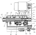
Fig. 1 is the structural representation of the utility model tack/beveler.
Fig. 2 is the structural representation of the feeding warehouse of the utility model tack/beveler.
Fig. 3 is the structural representation of the straight feeding device of the utility model tack/beveler.
Fig. 4 is the structural representation of the centering clamping device of the utility model tack/beveler.
Fig. 5 is the structural representation of the unit head of the utility model tack/beveler.
Fig. 6 is the structural representation of the cutterhead of the utility model tack/beveler.
The specific embodiment
For making those of ordinary skill in the art be expressly understood the purpose of this utility model, technical scheme and advantage more, the utility model is further elaborated below in conjunction with drawings and Examples.
Tack/beveler disclosed in the utility model is specially adapted to the tack and/or the chamfer machining of middle-size and small-size dc motor shell, certainly, also can be used for the tack and/or the chamfer machining of other similar workpiece.With reference to shown in Figure 1, this tack/beveler mainly by a support 10, a feeding warehouse 11, a straight feeding device 12, a feeding mechanical hand 13, a centering clamping device 14, a cutter arrangement 15, and a control device (not drawing among the figure) form.Wherein, feeding warehouse 11 is arranged on the support 10; Straight feeding device 12 is arranged at the below place of feeding warehouse 11, its bearing material portion when being in retracted mode corresponding to the discharging opening of this feeding warehouse 11; Feeding mechanical hand 13 is arranged on the support 10 with vertical mode, and the bearing material portion position when its material clamping part and straight feeding device 12 are in and stretch out state is corresponding; Centering clamping device 14 is arranged at the below place of feeding mechanical hand 14, and the material clamping part position that is in when stretching out state with this feeding mechanical hand 13 is corresponding; Cutter arrangement 15 includes two unit heads 16 and two and is installed on the both sides that cutterhead 17, two cutterheads 17 on the unit head 16 are divided into centering clamping device 14 respectively; Control device is installed on the support 10, is connected with straight feeding device 12, feeding mechanical hand 13, centering clamping device 14 and cutter arrangement 15 respectively, to control the operation of above-mentioned each mechanism.
When tack/beveler is worked, workpiece to be processed (for example middle-size and small-size dc motor shell) is put into feeding warehouse 11, usually, can determine once to put into the quantity of workpiece to be processed according to the capacity of this feeding warehouse 11.Workpiece to be processed relies on own wt and rolls into the bearing material portion of straight feeding device 12 from the discharging opening of this feeding warehouse 11, straight feeding device 12 stretches out and workpiece to be processed is delivered to the below place of this feeding mechanical hand 13, feeding mechanical hand 13 stretches out and withdraws after picking up the workpiece to be processed that places in the bearing material portion, and straight feeding device 12 is also withdrawn and entered the feeding work of next circulation.Feeding mechanical hand 13 stretches out once more and workpiece to be processed is delivered to this centering clamping device 14 places, and centering clamping device 14 clamps feeding mechanical hand 13 withdrawals behind the workpieces to be processed, and unit head 16 drives cutterhead 17 feedings and finishes tack and/or chamfer machining to workpiece.After the completion of processing, centering clamping device 14 unclamps, and workpiece is sent.Repetitive cycling like this, and can carry out tack and/or chamfered to workpiece continuously.
In conjunction with shown in Figure 2, feeding warehouse 11 includes one and is fixed in support 110, on the support 10 and is fixed in the perpendicular side plate 112 that the base plate that is obliquely installed 111 and two on this support 110 is located at these base plate 111 both sides respectively, like this, formed the discharging opening of this feeding warehouse 11 at the lower of this base plate 11 1, placed workpiece to be processed on this base plate 111 to rely on deadweight to roll out and fall into straight feeding device 12 from discharging opening.Preferably, one guiding mechanism 113 is set, to adjust the width of 112 of two perpendicular side plate at each perpendicular side plate 112 place.This guiding mechanism 113 includes a swivel nut 1130 and a screw rod 1131, and this swivel nut 1130 is fixedly arranged on the lateral surface place of perpendicular side plate 112, and this screw rod 1131 is arranged on the support plate 1100 that is fixed on the described support 110 rotationally, and is spirally connected with this swivel nut 1130.Rotate this screw rod 1131 and make this swivel nut 1130 produce displacements, and then drive perpendicular side plate 112 and move, and reach the purpose of adjusting the width between two perpendicular side plate 112.Lateral surface place in perpendicular side plate 112 is fixed with sleeve 114, plugs bolt 115 in this sleeve 114, this bolt 115 is connected on the support plate 1100, and between support plate 1100 and perpendicular side plate 112 extension spring 116 is set, to keep the steady of two perpendicular side plate 112.
In conjunction with shown in Figure 3, straight feeding device 12 is arranged at the place, below of described feeding warehouse 11, it includes a sliding sleeve 120, and passes described sliding sleeve 120 and the push rod 121 that can slide, its piston rod be connected in the bearing material portion 125 that is used to carry workpiece of these push rod 121 front ends by the promotion cylinder 123 and that one first contiguous block 122 is connected in these push rod 121 rear ends by one second contiguous block 124 in this sliding sleeve 120, promote cylinder 123 by this and promote this bearing material portion 125, and the workpiece that will be carried in the bearing material portion 125 is delivered to feeding mechanical hand 13 places.This bearing material portion 125 includes a socket 1250 and two that is fixedly connected with this second contiguous block 124 and keeps at a certain distance away and be inserted in plate 1251 on this socket 1250, is formed with a recess 1252 on this plate 1251, is used to carry workpiece to be processed.Bearing material portion 125 adopts the form of socket 1250 and plate 1251 combinations, can select the different plate of recess size 1251 for use, to adapt to the workpiece to be processed of different size.
Preferably, this straight feeding device 12 is provided with a centering mechanism 126, this centering body 126 includes a pulling cylinder 1260, one slide plate 1262 that connects with this pulling cylinder 1260 by connecting screw 1261, one slide 1263, two are arranged in this slide 1263 and the slide block 1264 that can slide in this slide 1263, two are installed on centering piece 1265 and two on two slide blocks 1264 respectively is individually fixed in pin wheel 1266 on two slide blocks 1264, wherein, be formed with the two arcuation chutes that are arranged in V-type each other on this slide plate 1262, two slide blocks 1264 are positioned at the top of this slide plate 1262, two set pin wheels 1266 are placed in respectively among two chutes of slide plate 1262 on it, two centering pieces 1265 are positioned at the outside of described plate 1251, and correspond respectively to the recess 1252 of described plate 1251.Pulling cylinder 1260 drives slide plate 1262, drive pin wheel 1266 by the chute on it, and then drive slide block 1264 moves with respect to bearing material portion 125 advance and retreat along slide 1263, thereby make centering piece 1265 to move towards plate 1251 advance and retreat, when centering piece 1265 when plate 1251 moves, it can act on the workpiece to be processed of the recess 1252 that places two plates 1251, and guarantee that workpiece is in correct position, be unfavorable for the carrying out of subsequent handling to prevent workpiece from the feeding process, position deviation occurring.
With reference to shown in Figure 1, feeding mechanical hand 13 can adopt common manipulator commonly used, it includes one and drives the material clamping part 131 that cylinder 130 and is fixedly arranged on the piston rod of this driving cylinder 130, this material clamping part 131 is provided with perpendicular to the bearing material portion 125 of straight feeding device 12, when straight feeding device 12 pushes workpiece to be processed to feeding mechanical hand 13 places, the material clamping part 131 of this feeding mechanical hand 13 stretches out under the driving that drives cylinder 130 and picks up workpiece, to treat that it is delivered to centering clamping device 14 places.
In conjunction with shown in Figure 4, centering clamping device 14 includes two toward each other and keep at a certain distance away and the fixed head 140 that is provided with, the place, inboard that is positioned at each fixed head 140 respectively is provided with a plate 141, the place, medial surface top of each connecting plate 141 is fixed with a clamp shaft 142, each clamp shaft 142 is provided with a clamping head 143, two clamping heads 143 and can clamps workpiece toward each other in the horizontal direction.Wherein, a fixed head 140 is provided with a cylinder 144, and the output shaft 1440 of this cylinder 144 passes fixed head 140 and connects so that this cylinder 144 can horizontal push-and-pull connecting plate 141 with connecting plate 141.In two connecting plates 141, wherein place, the medial surface bottom of a plate 141 is fixed with two first driving cog axles 145, and place, the medial surface bottom of another connecting plate 141 is fixed with two second driving cog axles 146, each first driving cog axle 145 and the second corresponding with it driving cog axle 146 are engaged in a travelling gear 147 jointly, and realize the synchronous interaction of the first driving cog axle 145 and the second driving cog axle 146.
During work, cylinder 144 starts, its output shaft 1440 levels promote connecting plate 141, first set on it the driving cog axle 145 promotes travelling gear 147 rotations, drive the second driving cog axle 146 towards the opposite direction displacement of the first driving cog axle 145, make that both are close to each other with the affixed connecting plate 141 of the second driving cog axle 146 with the affixed connecting plate of the first driving cog axle 145 141, and then, clamping head 143 set on two connecting plates 141 is close to each other, and can workpiece to be processed be clamped, by cutterhead to workpiece tack and/or chamfering; After the completion of processing, the output shaft 1440 of cylinder 144 connecting plate 141 of pulling back, the effect by first, second driving cog axle 145,146 separates two connecting plates 141, and then two clamping heads 143 and unclamp workpiece separately.The first driving cog axle 145, travelling gear 147 and the second driving cog axle 146 by above-mentioned set-up mode is to realize that clamping head 143 is for the clamping of workpiece or unclamp, guarantee uniformity and synchronism that two clamping heads 143 move to each other, played the effect of clamping work pieces better.
Preferably, the front end of clamping head 143 is formed with the clamping position 1430 of v-shaped structure, and it is clamping work pieces more firmly, is columned workpiece for profile especially.
One fixed head 140 is provided with a stopping means 148 and is positioned at the stroke of the connecting plate 141 of these fixed head 140 inboards with restriction, and is excessive and cause the infringement of centering clamping device with the stroke that prevents connecting plate 141.In the embodiment shown in fig. 4, this stopping means 148 includes one and is fixed in limit shaft 1481, and the limited block 1482 of fixing these limit shaft 1481 ends that fixed block 1480, on this fixed head 140 is connected on this fixed block 1480 and inwardly passes described fixed head 140 and connecting plate 141, like this, connecting plate 141 can be defined between fixed head 140 and the limited block 1482, prevent that its stroke is excessive.Usually, stopping means 148 is arranged on another fixed head 140 with respect to the fixed head 140 that is provided with cylinder 144.
Fall among the centering clamping device causing damage for fear of the foreign matter such as iron filings, can be outside it sheathed housing 149.In this embodiment, this housing 149 includes two end housings 1490 and two that are divided into two ends places and is arranged at mesochite 1491 between two end housings 1490.Wherein, fixed head 140 is fixed in the side place of end housing 1490, and connecting plate 141 is placed among the end housing 1490, and clamping head 143, the first driving cog axle 145, the second driving cog axle 146 stretch out in outside the end housing 1490; Mesochite 1491 is formed with the 3rd accommodation space 1494 that second accommodation space 1493 and that first accommodation space 1492, that is used to take in the first driving cog axle 145 is used to take in the second driving cog axle 146 is used to take in travelling gear 147.
In conjunction with shown in Figure 5, unit head 16 includes a casing 160, be fixed with a motor 161 on this casing 160, be fixed with one first timing belt pulley 1610 on the output shaft of motor 161, the driving member 162 that is provided with by a clutch shaft bearing 1620 on an end of casing 160, this driving member 162 is provided with one second timing belt pulley, 1621, the first timing belt pulleys 1610 and second timing belt pulley 1621 uses a synchronous belt 1611 to connect, and rotates and make motor 161 can drive this driving member 162.
Driving member 162 and one is located at main shaft 163 in this casing 160 and is movably connected and can drive this main shaft 163 rotations, and an end of this main shaft 163 stretches out in outside this casing 160 in the usefulness of installation cutterhead.The outer surface of this driving member 162 is arranged with one first gear 1622, and this first gear 1622 is meshed with differential gearing reducing gear 164 in being arranged at this casing 160, and the output shaft of this differential gearing reducing gear 164 is provided with an electric clutch 165.Be arranged with a sleeve 166 by second bearing 1630 outside main shaft 163, this sleeve 166 is arranged among the linear bearing 1660 that is fixed on this casing 160.Sleeve 160 is provided with second gear 1661 that is meshed with electric clutch 165, and locate to fix a cam 167 in its back-end, this cam 167 is inserted a spacer pin 1671 that is fixed on this casing 160 along the recessed curved slot 1670 that is formed with a closure of its outer surface in this groove 1670.
During work, motor 161 starts, driving driving member 162 by synchronous belt 1611 rotates, and then driving main shaft 163 and 1622 rotations of first gear, this first gear 1622 rotates sleeve 166 at a slow speed by the transmission of differential gearing reducing gear 164, electric clutch 165, second gear 1661.When this sleeve 166 rotated at a slow speed, alignment pin 1671 acted on groove 1670 and drive sleeve 166 axially-movables, and then drove main shaft 163 and move axially, and made the cutterhead that is installed on the main shaft 163 finish processing to workpiece to be processed.This groove 1670 can be arranged to finish F.F., worker with drive shaft 163 and advance, stops curvilinear structures with four programs of rewind down.Repetitive cycling like this, and the workpiece to be processed that enters the processing district is in turn carried out tack and/or chamfer machining.When cam 167 belonged to zero-bit, electric clutch 165 separated and no longer drive sleeve 166 rotations, and 163 on main shaft rotates and do not axially move.
Being provided with one by bearing outside main shaft 163 can axially movable sleeve 166, and a cam 167 with curve closed recess 1670 is set in the rear end of sleeve 166, drive sleeve 166 moves axially by an alignment pin 1671 effect grooves 1670 by the rotation at a slow speed of drive sleeve 166, and then drive main shafts 163 by sleeve 166 and move, and make the cutterhead that is installed on main shaft 163 can contact/leave workpiece to be processed, thereby finish tack and/or chamfer machining to workpiece.Because the setting of sleeve 166, main shaft 163 is rotated more reposefully and move axially, thus can make unit head 16 drive cutterhead 17 more reposefully, the accuracy of raising tack and/or chamfer machining.
Preferably, the installation position 1631 that is used to cutterhead 17 is installed that is formed at main shaft 163 front ends is designed to the Morse's taper installation position, and it matches with the cutterhead with Morse's taper handle of a knife, but realizes the cutterhead Fast Installation or dismantle in this main shaft 163.
Unit head is provided with the protective cover 1612 of described first timing belt pulley 1610 of a cover cap, second timing belt pulley 1621 and belt 1611, when unit head moves, the effect of this protective cover 1612 has two: one, can prevent that foreign matter from entering and operating belt pulley and belt are caused damage; The two prevents that operating belt pulley or belt from damaging operating personnel.
Preferably, this driving member 162 is a spline housing, and is provided with the splined shaft 1632 with this spline housing coupling in the rear end of main shaft 163, and splined shaft 1632 is plugged among the spline housing and drives main shaft 163 rotations by this spline housing.Adopt splined, have good to neutrality, guidance quality is good, can bear the big advantage of load.
In conjunction with shown in Figure 6, this cutterhead 17 includes a discoid cutter head 170, offer three grooves 1700 on the front end face of this cutter head 170, in this embodiment, three grooves 1700 are from the center outwards radial and are distributed on the front end face of cutter head 170, and the angle between the two adjacent grooves 1700 is 120 degree.Be provided with a knife rest 171 in each groove 1700, the bottom of this knife rest 171 is located outward-dipping and is formed with an outer inclined-plane 1710, and a briquetting 172 being set with immovable support 171 at each groove 1700, this briquetting 172 slopes inwardly and is formed with an interior inclined-plane 1720 that is matched with above-mentioned outer inclined-plane 1710.The interior inclined-plane 1720 of this briquetting 172 fits in the outer inclined-plane 1710 of this knife rest 171, and uses two first screws 1721 to pass this briquetting 172 and be screwed together in this cutter head 170, thereby realizes that briquetting 172 is pressed in knife rest 171.So, because that briquetting 172 is oppressed in the active area of knife rest 171 is bigger, can compress firm this knife rest 171 effectively on cutter head 170, it is loosening to have avoided knife rest 171 to take place in the chamfer machining process, the effect of raising chamfer machining.Blade 173 is fixedly arranged on the knife rest 171 by second screw 1730, in this embodiment, cutter head 170 is provided with three knife rests 171, and each knife rest 171 respectively is provided with a blade 173, like this, can be used for interior angle, exterior angle and the end face of cylindrical workpiece (for example middle-size and small-size dc motor shell) are processed operation.
In another embodiment, this cutterhead 17 is used for cylindric workpiece is carried out chamfer machining, then two knife rests 171 can be set on cutter head 170, and each knife rest 171 is provided with a blade 173, so, can carry out elaboration to the exterior angle and the end face of cylindric workpiece.
Cutterhead 17 respectively is provided with a set screw 174 corresponding to each knife rest 171 on the cutter head 170, is used for adjusting the position of knife rest 171, so that can carry out chamfer machining to the workpiece of different-diameter at groove 1700.In this embodiment, place, outer end at groove 1700 is provided with a support plate 175, this support plate 175 uses two the 3rd screws 1750 and is fixed on the cutter head 170, and set screw 174 spiral shells are crossed this support plate 175 and are screwed together in knife rest 171, thereby can play the effect of regulating knife rest 171 positions.
The rear end face place of cutter head 170 is fixed with a handle of a knife 176, to be used for that cutterhead 17 is connected in unit head 16.Preferably, this handle of a knife 176 is the Morse's taper handle of a knife, but makes cutterhead 17 Fast Installation or dismantle in unit head 16.
In sum, tack/beveler disclosed in the utility model is provided with a centering clamping device 14 that is used for Chinese style ground clamping workpiece to be processed, and respectively establish a cutter arrangement 15 in the both sides of centering clamping device, like this, can carry out tack and/or chamfer machining to the two ends of workpiece to be processed simultaneously, and need not operation break-down the two ends of workpiece to be processed are successively handled, improved the efficient of tack and/or chamfer machining.
The above only is a preferred embodiment of the present utility model, but not the utility model is done any form restriction, and all equivalent variations or modifications of being done in the claim scope all should fall within the protection domain of the present utility model.
Claims (10)
1. a tack/beveler is characterized in that, described tack/beveler includes:
One support (10);
One feeding warehouse (11) is arranged on the described support (10);
One straight feeding device (12) is arranged at the below place of described feeding warehouse (11), its bearing material portion (125) when being in retracted mode corresponding to the discharging opening of described feeding warehouse (11);
One feeding mechanical hand (13) is arranged on the described support (10) with vertical mode, and bearing material portion (125) position when its material clamping part (131) and described straight feeding device (12) are in and stretch out state is corresponding;
One centering clamping device (14) is arranged at the below place of described feeding mechanical hand (14), and material clamping part (131) position that is in when stretching out state with described feeding mechanical hand (13) is corresponding;
One cutter arrangement (15) includes two unit heads (16) and two and is installed on cutterhead (17) on the described unit head (16) respectively, and two cutterheads (17) are divided into the both sides of described centering clamping device (14);
One control device is connected with described straight feeding device (12), feeding mechanical hand (13), centering clamping device (14) and cutter arrangement (15) respectively, to control its operation.
2. tack/beveler as claimed in claim 1, it is characterized in that, described feeding warehouse (11) includes one and is fixed in support (110), on the described support (10) and is fixed in the perpendicular side plate (112) that the base plate that is obliquely installed (111) and two on the described support (110) is located at described base plate (111) both sides respectively, and the lower of described base plate (111) has formed the discharging opening of described feeding warehouse (11).
3. tack/beveler as claimed in claim 2 is characterized in that, each perpendicular side plate (112) locates to be provided with a guiding mechanism (113), to adjust the width between two perpendicular side plate (112).
4. tack/beveler as claimed in claim 3, it is characterized in that, described guiding mechanism (113) includes a swivel nut (1130) and a screw rod (1131), described swivel nut (1130) is fixedly arranged on the lateral surface place of described perpendicular side plate (112), described screw rod (1131) is arranged on the support plate (1100) that is fixed on the described support (110) rotationally, and is spirally connected with described swivel nut (1130).
5. tack/beveler as claimed in claim 1, it is characterized in that described straight feeding device (12) includes a sliding sleeve (120), and passes described sliding sleeve (120) and the push rod (121) that can slide, its piston rod be connected in the bearing material portion (125) that is used to carry workpiece of described push rod (121) front end by the promotion cylinder (123) and that one first contiguous block (122) is connected in described push rod (121) rear end by one second contiguous block (124) in this sliding sleeve (120).
6. tack/beveler as claimed in claim 5, it is characterized in that, described bearing material portion (125) includes a socket (1250) and two that is fixedly connected with described second contiguous block (124) and keeps at a certain distance away and be inserted in plate (1251) on the described socket (1250), is formed with a recess (1252) that is used to carry workpiece to be processed on the described plate (1251).
7. tack/beveler as claimed in claim 6, it is characterized in that, described straight feeding device (12) is provided with a centering mechanism (126), described centering body (126) includes a pulling cylinder (1260), one slide plate (1262) that connects with described pulling cylinder (1260) by a connecting screw (1261), one slide (1263), two are arranged in the described slide (1263) and the slide block (1264) that can slide in described slide (1263), two are installed on centering piece (1265) and two on two slide blocks (1264) respectively is individually fixed in pin wheel (1266) on two slide blocks (1264), be formed with the two arcuation chutes that are arranged in V-type each other on the described slide plate (1262), two slide blocks (1264) are positioned at the top of described slide plate (1262), set two pin wheels (1266) are placed in respectively among two chutes of described slide plate (1262) on it, two centering pieces (1265) are positioned at the outside of described plate (1251), and correspond respectively to the recess (1252) of described plate (1251).
8. tack/beveler as claimed in claim 1 is characterized in that, described centering clamping device (14) includes:
Two fixed heads (140) are provided with toward each other;
Two connecting plates (141), be divided into the place, inboard of two described fixed heads (140), wherein, the medial surface place of a plate (141) is fixed with at least one first driving cog axle (145), the medial surface place of another connecting plate (141) is fixed with at least one second driving cog axle (146), and described first driving cog axle (145) and the corresponding with it described second driving cog axle (146) are engaged in a travelling gear (147) jointly;
Two clamp shafts (142) are individually fixed in the medial surface place of two described connecting plates (141), and each clamp shaft (142) is provided with a clamping head (143), and two described clamping heads (143) in the horizontal direction toward each other;
One cylinder (144) is fixed on the described fixed head (141), and its output shaft (1440) passes described fixed head (140) and connects with described connecting plate (141).
9. tack/beveler as claimed in claim 1 is characterized in that, described unit head (16) includes:
One casing (160);
One motor (161), it is fixed on the described casing (160);
One driving member (162), it is arranged at an end of described casing (160) by a clutch shaft bearing (1620), and connects with described motor (161) and drive rotation by described motor (116), and is arranged with one first gear (1622) in its outer surface;
One main shaft (163) is arranged among the described casing (160), and the one end movably connects with described driving member (162), and the other end stretches out in outside the described casing (160) for the usefulness that cutterhead (17) is installed;
One differential gearing reducing gear (164), it is meshed with described first gear (1622), and its output shaft is provided with an electric clutch (165);
One sleeve (166), overcoat is arranged at described main shaft (163) by second bearing (1630), and be arranged among the linear bearing (1660) that is fixed in described casing (160), which is provided with second gear (1661) that is meshed with described electric clutch (165), and one cam (167) is installed in rear end, described cam (167) is inserted a spacer pin (1671) that is fixed on the described casing (160) along the recessed curved slot (1670) that is formed with a closure of its outer surface in the described groove (1670).
10. tack/beveler as claimed in claim 1, it is characterized in that, described cutterhead (17) includes a cutter head (170), offer at least one groove (1700) from the center to external radiation on the front end face of described cutter head (170), be provided with a knife rest (171) that is fixed with blade (173) in each groove (1700), the bottom of described knife rest (171) is located outward-dipping and is formed with an outer inclined-plane (1710), and a briquetting (172) is set with fixing described knife rest (171) at each groove (1700), described briquetting (172) slopes inwardly and is formed with an interior inclined-plane (1720) that is matched with described outer inclined-plane (1710), inclined-plane (1720) fits in described outer inclined-plane (1710) in described, and use at least one first screw (1721) to pass described briquetting (172) and be screwed together in described cutter head (170), and make described briquetting (172) be pressed in described knife rest (171).
Priority Applications (1)
| Application Number | Priority Date | Filing Date | Title |
|---|---|---|---|
| CN2010201219047U CN201644885U (en) | 2010-02-26 | 2010-02-26 | Beveling/chamfering machine |
Applications Claiming Priority (1)
| Application Number | Priority Date | Filing Date | Title |
|---|---|---|---|
| CN2010201219047U CN201644885U (en) | 2010-02-26 | 2010-02-26 | Beveling/chamfering machine |
Publications (1)
| Publication Number | Publication Date |
|---|---|
| CN201644885U true CN201644885U (en) | 2010-11-24 |
Family
ID=43110088
Family Applications (1)
| Application Number | Title | Priority Date | Filing Date |
|---|---|---|---|
| CN2010201219047U Expired - Lifetime CN201644885U (en) | 2010-02-26 | 2010-02-26 | Beveling/chamfering machine |
Country Status (1)
| Country | Link |
|---|---|
| CN (1) | CN201644885U (en) |
Cited By (19)
| Publication number | Priority date | Publication date | Assignee | Title |
|---|---|---|---|---|
| CN102151841A (en) * | 2010-12-31 | 2011-08-17 | 东莞市新志密封技术有限公司 | Method for chamfering polytetrafluoroethylene guide tape and chamfering machine |
| CN102506144A (en) * | 2011-11-01 | 2012-06-20 | 无锡威华电焊机制造有限公司 | Transmission driving mechanism of plate chamfering machine |
| CN102554360A (en) * | 2012-02-04 | 2012-07-11 | 余胜东 | Combined machine tool with bench drill in horizontal arrangement for simultaneously performing chamfering of double heads |
| CN103009202A (en) * | 2012-12-20 | 2013-04-03 | 深圳市华测检测技术股份有限公司 | Automatic chamfering machine |
| CN103934512A (en) * | 2014-05-09 | 2014-07-23 | 南京众得利自动化机械有限公司 | Chamfering knife rest device with ejection pin |
| CN104440357A (en) * | 2014-12-11 | 2015-03-25 | 无锡大龙马数控机床制造有限责任公司 | Circular shaft feeding positioning device |
| CN104741700A (en) * | 2015-04-08 | 2015-07-01 | 浙江正康实业有限公司 | Automatic faced machine of elbow pipe |
| CN104759698A (en) * | 2015-03-10 | 2015-07-08 | 天津杰锋钢管工贸有限公司 | Inner and outer chamfering cutter head of end facing machine |
| CN104841993A (en) * | 2015-06-01 | 2015-08-19 | 天津大学 | Full-automatic valve rod square milling machine |
| CN105057799A (en) * | 2015-07-23 | 2015-11-18 | 苏州纽东精密制造科技有限公司 | Double-end chamfering machine and use method thereof |
| CN106002459A (en) * | 2016-07-26 | 2016-10-12 | 东莞市晋诚机械有限公司 | Chamfering machine |
| CN106001617A (en) * | 2016-07-25 | 2016-10-12 | 天津博瑞泰机械零部件有限公司 | Double-headed automatic chamfering machine for pipe fittings |
| CN106041127A (en) * | 2016-06-27 | 2016-10-26 | 海天塑机集团有限公司 | Machine tool for automatically chamfering inner and outer corners and flattening end surfaces of pipe fittings |
| CN106041217A (en) * | 2016-08-01 | 2016-10-26 | 盐城工业职业技术学院 | Piston ring chamfering machine |
| CN106112073A (en) * | 2016-08-02 | 2016-11-16 | 盛瑞传动股份有限公司 | Piston pin two ends facing attachment |
| CN107824845A (en) * | 2017-11-17 | 2018-03-23 | 黄石市三木塑料模具有限公司 | Mold base process automation process units |
| CN108500772A (en) * | 2018-06-04 | 2018-09-07 | 江苏甬润工具有限公司 | A kind of chamfering tool of automatic loading/unloading |
| CN112935355A (en) * | 2021-04-06 | 2021-06-11 | 浙江威能消防器材股份有限公司 | Automatic double-end chamfer of aluminium bar mills flat machine |
| CN113001299A (en) * | 2021-01-27 | 2021-06-22 | 石伟 | Automatic chamfering device for copper bush |
-
2010
- 2010-02-26 CN CN2010201219047U patent/CN201644885U/en not_active Expired - Lifetime
Cited By (25)
| Publication number | Priority date | Publication date | Assignee | Title |
|---|---|---|---|---|
| CN102151841B (en) * | 2010-12-31 | 2015-09-30 | 广东新志密封技术有限公司 | A kind of method of polytetrafluoroethylene (PTFE) guidance tape chamfering and beveler |
| CN102151841A (en) * | 2010-12-31 | 2011-08-17 | 东莞市新志密封技术有限公司 | Method for chamfering polytetrafluoroethylene guide tape and chamfering machine |
| CN102506144A (en) * | 2011-11-01 | 2012-06-20 | 无锡威华电焊机制造有限公司 | Transmission driving mechanism of plate chamfering machine |
| CN102554360A (en) * | 2012-02-04 | 2012-07-11 | 余胜东 | Combined machine tool with bench drill in horizontal arrangement for simultaneously performing chamfering of double heads |
| CN103009202B (en) * | 2012-12-20 | 2015-04-15 | 深圳市华测检测技术股份有限公司 | Automatic chamfering machine |
| CN103009202A (en) * | 2012-12-20 | 2013-04-03 | 深圳市华测检测技术股份有限公司 | Automatic chamfering machine |
| CN103934512A (en) * | 2014-05-09 | 2014-07-23 | 南京众得利自动化机械有限公司 | Chamfering knife rest device with ejection pin |
| CN104440357A (en) * | 2014-12-11 | 2015-03-25 | 无锡大龙马数控机床制造有限责任公司 | Circular shaft feeding positioning device |
| CN104759698A (en) * | 2015-03-10 | 2015-07-08 | 天津杰锋钢管工贸有限公司 | Inner and outer chamfering cutter head of end facing machine |
| CN104741700A (en) * | 2015-04-08 | 2015-07-01 | 浙江正康实业有限公司 | Automatic faced machine of elbow pipe |
| CN104841993A (en) * | 2015-06-01 | 2015-08-19 | 天津大学 | Full-automatic valve rod square milling machine |
| CN105057799A (en) * | 2015-07-23 | 2015-11-18 | 苏州纽东精密制造科技有限公司 | Double-end chamfering machine and use method thereof |
| CN106041127A (en) * | 2016-06-27 | 2016-10-26 | 海天塑机集团有限公司 | Machine tool for automatically chamfering inner and outer corners and flattening end surfaces of pipe fittings |
| CN106001617A (en) * | 2016-07-25 | 2016-10-12 | 天津博瑞泰机械零部件有限公司 | Double-headed automatic chamfering machine for pipe fittings |
| CN106002459A (en) * | 2016-07-26 | 2016-10-12 | 东莞市晋诚机械有限公司 | Chamfering machine |
| CN106002459B (en) * | 2016-07-26 | 2018-07-20 | 东莞市晋诚机械有限公司 | A kind of beveler |
| CN106041217A (en) * | 2016-08-01 | 2016-10-26 | 盐城工业职业技术学院 | Piston ring chamfering machine |
| CN106041217B (en) * | 2016-08-01 | 2018-07-06 | 盐城工业职业技术学院 | Piston ring chamfer machine |
| CN106112073A (en) * | 2016-08-02 | 2016-11-16 | 盛瑞传动股份有限公司 | Piston pin two ends facing attachment |
| CN107824845A (en) * | 2017-11-17 | 2018-03-23 | 黄石市三木塑料模具有限公司 | Mold base process automation process units |
| CN108500772A (en) * | 2018-06-04 | 2018-09-07 | 江苏甬润工具有限公司 | A kind of chamfering tool of automatic loading/unloading |
| CN108500772B (en) * | 2018-06-04 | 2024-02-23 | 台州市典雅智能设备有限公司 | Chamfering tool capable of automatically feeding and discharging |
| CN113001299A (en) * | 2021-01-27 | 2021-06-22 | 石伟 | Automatic chamfering device for copper bush |
| CN112935355A (en) * | 2021-04-06 | 2021-06-11 | 浙江威能消防器材股份有限公司 | Automatic double-end chamfer of aluminium bar mills flat machine |
| CN112935355B (en) * | 2021-04-06 | 2024-04-05 | 浙江威能消防器材股份有限公司 | Automatic double-end chamfer milling machine for aluminum bars |
Similar Documents
| Publication | Publication Date | Title |
|---|---|---|
| CN201644885U (en) | Beveling/chamfering machine | |
| CN101774137B (en) | Numerical control drill double relief angle blade milling machine | |
| CN112404531B (en) | Automatic horizontal milling machine | |
| CN201913463U (en) | Horizontal double-faced numerical control machine tool for milling end face and drilling central hole | |
| CN211219933U (en) | Multi-angle adjustable polycrystalline diamond grinding device for cutter | |
| CN112139515B (en) | Vertical lathe for machining distance ring and machining process of distance ring | |
| CN212122646U (en) | Grinding machine convenient to processing taper hole | |
| CN208067794U (en) | A kind of rotating integrated device of clamping and system of processing | |
| CN211464944U (en) | Double-station full-automatic pipe connecting and processing device | |
| CN2535172Y (en) | Rotary-cutting pipe-cutting machine | |
| CN216541254U (en) | Automatic tooth machine of attacking of double-end | |
| CN201366637Y (en) | Numerically controlled double-back angle edge grinder for bits | |
| CN116214283A (en) | End mill grinding device and operation method | |
| CN214869187U (en) | Spherical roller bearing plunge grinding machine | |
| CN210281649U (en) | Circular mouth knife edging machine tool | |
| CN115781294A (en) | Environment-friendly conveying cylinder turning and polishing integrated machine and using method thereof | |
| CN101518899B (en) | Cross-axle universal-joint mill shaft diameter manipulator device | |
| CN213163298U (en) | Plane milling machine convenient to clearance disintegrating slag | |
| CN108908061A (en) | A kind of mechanical fitting polishing machine | |
| CN110303391A (en) | Round mouth knife puts the first edge on a knife or a pair of scissors lathe | |
| CN216759264U (en) | Tooling for processing burrs on flat square of carrier roller shaft | |
| CN220279126U (en) | Core sample double-end-face grinding machine | |
| CN213615742U (en) | Special grinding equipment for hexagonal external thread joint | |
| CN211438942U (en) | Flywheel disc grinding machine | |
| CN211218876U (en) | Automatic square milling machine with calendar function for fine stem |
Legal Events
| Date | Code | Title | Description |
|---|---|---|---|
| C14 | Grant of patent or utility model | ||
| GR01 | Patent grant | ||
| CX01 | Expiry of patent term | ||
| CX01 | Expiry of patent term |
Granted publication date: 20101124 |