CN201641935U - Novel dish washing machine - Google Patents
Novel dish washing machine Download PDFInfo
- Publication number
- CN201641935U CN201641935U CN2009201393430U CN200920139343U CN201641935U CN 201641935 U CN201641935 U CN 201641935U CN 2009201393430 U CN2009201393430 U CN 2009201393430U CN 200920139343 U CN200920139343 U CN 200920139343U CN 201641935 U CN201641935 U CN 201641935U
- Authority
- CN
- China
- Prior art keywords
- cell body
- cleaning
- water
- body housing
- transmission device
- Prior art date
- Legal status (The legal status is an assumption and is not a legal conclusion. Google has not performed a legal analysis and makes no representation as to the accuracy of the status listed.)
- Expired - Fee Related
Links
Images


Abstract
The utility model discloses a novel dish washing machine which mainly comprises a washing tank body housing, a transmission device, a rotary swinging arm, a bottom tank, an ultrasonic generator and a water storage tank, wherein the washing tank body housing is divided into an upper cavity tank body and a lower cavity tank body through a baffle plate arranged in the middle thereof; the bottom tank adopts a container with a plurality of tank cavities and is mounted in the upper cavity tank body; the ultrasonic generator is mounted in the ultrasonic hot water washing tank; the transmission device is mounted on the baffle plate in the middle of the washing tank body housing; the rotary swinging arm is sleeved on the transmission device; and the water storage tank is mounted in the lower cavity tank body of the washing tank body housing and positioned below the high-pressure sprinkling station and the clear water sprinkling station of the bottom tank. The washing tank body housing adopts a rectangular shape, so that the station conversion is realized through the rotation of the rotary swinging arm mounted on the transmission device driven by the rotation of the transmission device. Compared with the conventional dish washing machine in an assembly line, the utility model has the advantages of compact structure and less occupied area.
Description
Technical field
The utility model relates to a kind of dish-washing apparatus, particularly relates to a kind of novel dish-washing machines.
Background technology
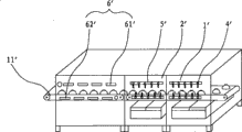
Along with people are more and more higher to the sanitary tableware requirement of catering trade, yet tableware cleaning equipment is very uneconomical completely for the complete cleaning and sterilizing of restaurant's configuration feature, objectively requires a kind of equipment that can clean tableware in a large number to provide the service of cleaning for each catering trade in the society.What present dish-washing apparatus mostly adopted is the pipelining mode, tableware is cleaned, sterilizes, disclose a kind of wash dishes dried disinfecting all-in-one (as shown in Figure 1) as Chinese patent 200720085268.5, what comprise closed integral structure slightly washes unit 1 ', cleaning unit 2 ', dried disinfecting unit 6 ', electric gear shift(ing) transmission mechanism.The described unit 1 ' of slightly washing is provided with high pressure water jet pipe 4 ', and cleaning unit 2 ' is provided with low pressure sparge pipe 5 ', and dried disinfecting unit 6 ' is provided with the high-power far infrared electric boiling plate 61 ' of many groups; The high-power far infrared electric boiling plate 61 ' of many groups in settings of insulating relatively of dried disinfecting guipure chain 11 ' upper and lower, is organized the 61 ' parallel connection of far infrared electric boiling plate more and is connected with power supply respectively.It is bigger that the dish-washing apparatus that this pipelining mode is cleaned accounts for area.
The utility model content
The purpose of this utility model is to provide that a kind of floor space is little, cleaning and oven dry and bactericidal effect is good, water use efficiency is high novel energy-conserving dish-washing machine.
For achieving the above object, technical solution of the present utility model is:
The utility model is a kind of novel dish-washing machines, and it is mainly formed by cleaning cell body housing, transmission device, rotation swing arm, kerve, supersonic generator, water storage box etc.; The dividing plate that described cleaning cell body housing is set up in the middle is divided into epicoele cell body and cavity of resorption cell body; Described kerve is the container that is provided with a plurality of vallecular cavities, and it is installed in the epicoele cell body, and supersonic generator is installed in the ultrasonic wave hot water rinse bath; Described transmission device is installed on the dividing plate that cleans cell body housing middle part, and rotatable swing arm is socketed on the transmission device; Described water storage box is installed in the cavity of resorption cell body position of cleaning the cell body housing.
Described cell body is provided with input and output material, high-pressure spraying, ultrasonic wave cleaning, clear water spray, the first heat oven dry and second heat and dries six vallecular cavities such as sterilization, these six vallecular cavities correspondence respectively advance loading and unloading spray station, the first ultrasonic wave washing station, high-pressure spraying station, the second ultrasonic wave washing station, clear water spray station, the first hot drying station and the second heat oven dry sterilization station.
The utility model also comprises a upper cover plate movable up and down, the end face of described upper cover plate is provided with a hook and is provided with at least two positioning round orifice, loam cake circles or whirl in the air and is enclosed within on the rotary frame of transmission device, the hook of upper cover plate end face can articulate or break away from the special-purpose positioning hanger of being installed on the frame top of cleaning the cell body housing, and upper cover plate can cover the open port of kerve along with outstanding liter the up and down of machine; At least be provided with six pyramid type locating pieces on the same circumference of described rotation swing arm upper surface, the locating hole of upper cover plate end face is movable to be socketed on the pyramid type locating piece, makes that upper cover plate can be with rotation swing arm dial rotation.
Described cleaning cell body water storage box is divided into material loading material loading high-pressure spraying tank, ultrasonic heat cleaning by degreasing tank and ultrasonic wave hot water rinse bath and clean water heat water-spraying groove by dividing plate, and these four tanks are communicated with by high-pressure spraying water pump, ultrasonic wave clean cycle water pump, hot water hot water clear water spray water pump and bottom reservoir interior ultrasonic heat cleaning by degreasing tank, ultrasonic wave hot water rinse bath, clean water heat water-spraying's groove respectively.
Described transmission device mainly is made up of electric rotating machine, rotary frame, rising screw mandrel, last lifting motor, motor fixing frame, hoistable platform; Described electric rotating machine is installed in the top of cleaning cell body housing frame, and it connects and the affixed hoistable platform of rotation swing arm by rotary frame; Being fixed in rising screw mandrel on the rising motor output shaft is spirally connected to pass hoistable platform and can promote hoistable platform and moves up and down; The described lifting motor of going up is installed on the motor fixing frame, and motor fixing frame is installed on the dividing plate that cleans cell body housing middle part.
The utility model also comprises a ring flange; Described electric rotating machine is installed in the top of rotary frame, and the output shaft of electric rotating machine is fixed in ring flange vertically downward; Described rotary frame is made of many guide rods and connecting plate, and the mesopore of connecting plate is fixedly sleeved on ring flange, and the upper end of many guide rods is fixed on the connecting plate and is looped around the periphery of its mesopore, and the lower end of many guide rods is fixed on the motor fixing frame; Described hoistable platform is actively socketed on the many guide rods by a plurality of guide pin bushings, the fixedly sleeved screw mandrel cover at the middle part of hoistable platform; Described rising screw mandrel passes hoistable platform from bottom to top and is spirally connected with the screw mandrel cover at hoistable platform middle part, and the upper end of rising screw mandrel is nested with on ring flange by the bearing activity, and the lower end of rising screw mandrel is connected with the output shaft of last lifting motor by shaft joint.
After adopting such scheme, the utlity model has following advantage:
1, because the rectangular shape of cleaning cell body housing of the present utility model, conversion between each station is that the rotation by transmission device drives the rotation swing arm that is installed on it and realizes rotating, with respect to the dish-washing machine of commonly using with the streamline transporting pattern, compact conformation of the present utility model, floor space is less.
2, the utility model adopts ultrasonic wave to clean and sprays and clear water spray and technologies such as high-temperature baking and ultraviolet sterilization in conjunction with high-pressure water heating, and cleaning performance and drying effect and bactericidal effect are good.
3, liquid storage water tank of the present utility model is divided into material loading high-pressure spraying tank, ultrasonic heat cleaning by degreasing tank and ultrasonic wave hot water rinse bath by dividing plate, these three tanks supply water the cyclic utilization rate of water and cleannes height by ultrasonic heat cleaning by degreasing tank, ultrasonic wave hot water rinse bath, clean water heat water-spraying's groove of high pressured water circuling pump in kerve respectively.
4, transmission device of the present utility model is by electric rotating machine control station rotation conversion, the rising Electric Machine Control is used to place the rising and the decline of cleaning frame rotation swing arm, thereby, having realized the conversion of tableware between each station preferably, structure is comparatively simple, reliable in action.
Below in conjunction with the drawings and specific embodiments the utility model is further described.
Description of drawings
Fig. 1 is the structural representation of the wash dishes dried disinfecting all-in-one commonly used;
Fig. 2 is a cutaway view of the present utility model;
Fig. 3 is that the utility model removes the vertical view that cleans cell body housing top cover;
Fig. 4 is the vertical view of the utility model kerve;
Fig. 5 A, Fig. 5 B are that the utility model upper cover plate tangles state diagram and disengaged position figure;
Fig. 6 is the structure chart of the utility model transmission device;
Fig. 7 A, Fig. 7 B, Fig. 7 C are front view, vertical view and the side views of the utility model water storage box;
Fig. 8 is the front view of the utility model upper cover plate hook;
Fig. 9 is the front view that the utility model cleans cell body housing positioning hanger.
The specific embodiment
As Fig. 2, shown in Figure 3, the utility model is a kind of novel dish-washing machines, and it mainly is made up of cleaning cell body housing 1, transmission device 2, upper cover plate 3, rotation swing arm 4, kerve 5, supersonic generator 6, water storage box 7.
The dividing plate 11 that described cleaning cell body housing 1 is set up in the middle is divided into epicoele cell body 12 and cavity of resorption cell body 13.
Shown in Figure 2 as Fig. 4 reference, described kerve 5 is provided with six vallecular cavities such as material loading high-pressure spraying tank 51, ultrasonic heat cleaning by degreasing tank 52, ultrasonic wave hot water rinse bath 53, clean water heat water-spraying's groove 54, first heat oven dry 55 vallecular cavities and the second heat oven dry vallecular cavity 56, these six vallecular cavities correspondence respectively advance loading and unloading spray station, the first ultrasonic wave washing station, high-pressure spraying station, the second ultrasonic wave washing station, clear water spray station, the first hot drying station and the second heat oven dry sterilization station.Kerve 5 is installed in the epicoele cell body 12, and supersonic generator 6 is installed in the ultrasonic wave hot water rinse bath 53.
With reference to shown in Figure 4, described transmission device 2 is installed on the dividing plate 11 that cleans cell body housing 1 middle part as Fig. 2, and rotation swing arm 4 is socketed on the transmission device 2; Described water storage box 7 be installed in the cavity of resorption cell body 13 that cleans cell body housing 1 and be positioned at kerve 5 ultrasonic heat cleaning by degreasing tanks 52 and clean water heat water-spraying groove 54 under.
With reference to shown in Figure 1, the end face of described can be upper and lower mobile upper cover plate 3 is provided with 33 and six locating holes 34 of a hook as Fig. 5 A, Fig. 5 B, and upper cover plate 3 skies are enclosed within on the rotary frame 23 of transmission device 2; On the same circumference of rotation swing arm 4 upper surfaces, be provided with six pyramid type locating pieces 41 (as shown in Figure 1), locating hole 34 movable being socketed on the pyramid type locating piece 41 of upper cover plate 3 end faces, make that upper cover plate 3 can be with rotation swing arm 4 dial rotation, and the hook 33 that makes upper cover plate 3 end faces can articulate (shown in Fig. 5 A) or break away from the special-purpose positioning hanger of being installed on the frame top of (shown in Fig. 5 B) cleaning cell body housing 1 14, pyramid type locating piece 41 is with upper cover plate 3 accurate jack-up, and the spinning movement by machine realizes and the positioning hanger 14 that cleans the frame top of cell body housing 1 hangs over upper cover plate 3 on the hook 14, and it can be used as the sealing loam cake of kerve 5 when work and uses.Upper cover plate 3 can cover the open port of kerve 5, the loam cake function during as each technology groove duty along with outstanding liter the up and down of machine.On upper cover plate 3, also be provided with high-pressure spraying dish 31 and clear water spray dish 32, water under high pressure spray head and devices such as hot blast spray head and ultraviolet sterilizer are installed.
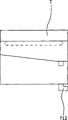
As Fig. 7 A, Fig. 7 B, Fig. 7 C is with reference to shown in Figure 4, described water storage box 7 is divided into material loading high-pressure spraying tank 71 by dividing plate, ultrasonic heat cleaning by degreasing tank 72 and ultrasonic wave hot water rinse bath and clean water heat water-spraying groove 73, these four tanks are respectively by high-pressure spraying water pump 74, ultrasonic wave clean cycle water pump 75, hot water clear water spray water pump 76 and the interior ultrasonic heat cleaning by degreasing tank 52 of kerve 5 bottom reservoirs, ultrasonic wave hot water rinse bath 53, clean water heat water-spraying's groove 54 is communicated with, and promptly water pump extracts material loading high-pressure spraying tank 71 respectively, water in ultrasonic heat cleaning by degreasing tank 72 and the ultrasonic wave hot water rinse bath 73 is to ultrasonic heat cleaning by degreasing tank 52, ultrasonic wave hot water rinse bath 53, clean water heat water-spraying's groove 54 water sprays.On material loading high-pressure spraying tank 71, be provided with clear water supply port 711 and discharge outlet 712, be provided with discharge outlet 721 at ultrasonic heat cleaning by degreasing tank 72, be provided with the overflow mouth of a river 73 and discharge outlet 732 at ultrasonic wave hot water rinse bath 73 tail ends, dividing plate between each tank reduces step by step, make the water of material loading high-pressure spraying tank 71 can flow into ultrasonic heat cleaning by degreasing tank 72, the water of ultrasonic heat cleaning by degreasing tank 72 can flow into ultrasonic wave hot water rinse bath 73.
As shown in Figure 6, described transmission device 2, it mainly is made up of electric rotating machine 21, ring flange 22, rotary frame 23, rising screw mandrel 24, last lifting motor 25, motor fixing frame 26, hoistable platform 27.
Described electric rotating machine 21 is installed in the top of cleaning cell body housing 1 and the top that is positioned at rotary frame 23, and the output shaft of electric rotating machine 21 is fixed in ring flange 22 vertically downward.
Described rotary frame 23 is made of three guide rods 231 and connecting plate 232.The mesopore of connecting plate 232 is fixedly sleeved on ring flange 22, and the upper end of three guide rods 231 is fixed on the connecting plate 232 and is looped around the periphery of its mesopore, and the lower end of three guide rods 231 is fixed on the motor fixing frame 26; Described hoistable platform 27 is actively socketed on respectively on three guide rods 231 by three guide pin bushings 233, the fixedly sleeved screw mandrel cover 241 at the middle part of hoistable platform 27, the rotation swing arm 4 that is used to place tableware framework 10 is fixed in hoistable platform 27, can rise, descend or rotation with hoistable platform 27; Described rising screw mandrel 24 passes hoistable platform 27 from bottom to top and is spirally connected with the screw mandrel at hoistable platform 7 middle parts cover 241, the upper end of rising screw mandrel 24 is nested with on ring flange 22 by the bearing activity, and the lower end of rising screw mandrel 24 is connected with the output shaft of last lifting motor 25 by shaft joint 28; The described lifting motor 25 of going up is installed on the motor fixing frame 26, and motor fixing frame 26 is installed on the dividing plate 11 that cleans cell body housing 1 middle part.
As shown in Figure 6, operation principle of the present utility model:
1, hoistable platform 27 rises: when tableware framework 10 is placed on rotation swing arm 4 turnover material levels, last lifting motor 25 is rotated in the forward, drive 24 rotations of rising screw mandrel, the feasible screw mandrel cover 241 that is spirally connected with rising screw mandrel 24 rises, the hoistable platform 27, the rotation swing arm 4 that are fixed on the screw mandrel cover 241 are risen synchronously along the guide rod 231 of rotary frame 23, and rotation swing arm 4 rises to and breaks away from kerve 5 backs and go up lifting motor 25 and stop to move;
2, hoistable platform 27 rotates: electric rotating machine 21 actions, and the output shaft of electric rotating machine 21 is by angle of ring flange 22 driven rotary frames, 23 rotations, and electric rotating machine 21 stops the rotation;
3, hoistable platform 27 descends: go up lifting motor 25 reverse rotations, drive 24 rotations of rising screw mandrel, the feasible screw mandrel cover 241 that is spirally connected with rising screw mandrel 24 descends, the hoistable platform 27, the rotation swing arm 4 that are fixed on the screw mandrel cover 241 descend synchronously along the guide rod 231 of rotary frame 23, after rotation swing arm 4 dropped in the kerve 5, last lifting motor 25 stopped action.As Fig. 7 A, Fig. 7 B, Fig. 7 C with reference to shown in Figure 4, the water that high-pressure spraying water pump 74, ultrasonic wave clean cycle water pump 75, hot water clear water spray water pump 76 extract respectively in material loading high-pressure spraying tank 71, ultrasonic heat cleaning by degreasing tank 72 and the ultrasonic wave hot water rinse bath 73 is sprayed water to ultrasonic heat cleaning by degreasing tank 52, ultrasonic wave hot water rinse bath 53, clean water heat water-spraying's groove 54, begins to clean.
4, repeat above-mentioned action, carry out the conversion between each station.
The above, it only is the utility model preferred embodiment, so can not limit the scope that the utility model is implemented with this, i.e. the equivalence of doing according to the utility model claim and description changes and modifies, and all should still belong in the scope that the utility model patent contains.So, all scopes that all belongs to the utility model protection of changing station in the revolution mode.
Claims (6)
1. novel dish-washing machines is characterized in that: it is mainly formed by cleaning cell body housing, transmission device, rotation swing arm, kerve, supersonic generator, water storage box; The dividing plate that described cleaning cell body housing is set up in the middle is divided into epicoele cell body and cavity of resorption cell body; Described kerve is the container that is provided with a plurality of vallecular cavities, and it is installed in the epicoele cell body, and supersonic generator is installed in the ultrasonic wave hot water rinse bath; Described transmission device is installed on the dividing plate that cleans cell body housing middle part, and rotatable swing arm is socketed on the transmission device; Described water storage box is installed in the cavity of resorption cell body position of cleaning the cell body housing.
2. novel dish-washing machines according to claim 1, it is characterized in that: described cell body is provided with input and output material, high-pressure spraying, ultrasonic wave cleaning, clear water spray, the first heat oven dry and second heat and dries six vallecular cavities such as sterilization, these six vallecular cavities correspondence respectively advance loading and unloading spray station, the first ultrasonic wave washing station, high-pressure spraying station, the second ultrasonic wave washing station, clear water spray station, the first hot drying station and the second heat oven dry sterilization station.
3. novel dish-washing machines according to claim 1, it is characterized in that: it also comprises a upper cover plate movable up and down, the end face of described upper cover plate is provided with a hook and is provided with at least two positioning round orifice, loam cake circles or whirl in the air and is enclosed within on the rotary frame of transmission device, the hook of upper cover plate end face can articulate or break away from the special-purpose positioning hanger of being installed on the frame top of cleaning the cell body housing, and upper cover plate can cover the open port of kerve along with outstanding liter the up and down of machine; At least be provided with six pyramid type locating pieces on the same circumference of described rotation swing arm upper surface, the locating hole of upper cover plate end face is movable to be socketed on the pyramid type locating piece, makes that upper cover plate can be with rotation swing arm dial rotation.
4. novel dish-washing machines according to claim 1 and 2, it is characterized in that: described cleaning cell body water storage box is divided into material loading high-pressure spraying tank, ultrasonic heat cleaning by degreasing tank and ultrasonic wave hot water rinse bath and clean water heat water-spraying groove by dividing plate, and these four tanks are communicated with by high-pressure spraying water pump, ultrasonic wave clean cycle water pump, hot water hot water clear water spray water pump and bottom reservoir interior ultrasonic heat cleaning by degreasing tank, ultrasonic wave hot water rinse bath, clean water heat water-spraying's groove respectively.
5. novel dish-washing machines according to claim 1 is characterized in that: described transmission device mainly is made up of electric rotating machine, rotary frame, rising screw mandrel, last lifting motor, motor fixing frame, hoistable platform; Described electric rotating machine is installed in the top of cleaning cell body housing frame, and it connects and the affixed hoistable platform of rotation swing arm by rotary frame; Being fixed in rising screw mandrel on the rising motor output shaft is spirally connected to pass hoistable platform and can promote hoistable platform and moves up and down; The described lifting motor of going up is installed on the motor fixing frame, and motor fixing frame is installed on the dividing plate that cleans cell body housing middle part.
6. novel dish-washing machines according to claim 5 is characterized in that: it also comprises a ring flange; Described electric rotating machine is installed in the top of rotary frame, and the output shaft of electric rotating machine is fixed in ring flange vertically downward; Described rotary frame is made of many guide rods and connecting plate, and the mesopore of connecting plate is fixedly sleeved on ring flange, and the upper end of many guide rods is fixed on the connecting plate and is looped around the periphery of its mesopore, and the lower end of many guide rods is fixed on the motor fixing frame; Described hoistable platform is actively socketed on the many guide rods by a plurality of guide pin bushings, the fixedly sleeved screw mandrel cover at the middle part of hoistable platform; Described rising screw mandrel passes hoistable platform from bottom to top and is spirally connected with the screw mandrel cover at hoistable platform middle part, and the upper end of rising screw mandrel is nested with on ring flange by the bearing activity, and the lower end of rising screw mandrel is connected with the output shaft of last lifting motor by shaft joint.
Priority Applications (1)
| Application Number | Priority Date | Filing Date | Title |
|---|---|---|---|
| CN2009201393430U CN201641935U (en) | 2009-07-01 | 2009-07-01 | Novel dish washing machine |
Applications Claiming Priority (1)
| Application Number | Priority Date | Filing Date | Title |
|---|---|---|---|
| CN2009201393430U CN201641935U (en) | 2009-07-01 | 2009-07-01 | Novel dish washing machine |
Publications (1)
| Publication Number | Publication Date |
|---|---|
| CN201641935U true CN201641935U (en) | 2010-11-24 |
Family
ID=43107113
Family Applications (1)
| Application Number | Title | Priority Date | Filing Date |
|---|---|---|---|
| CN2009201393430U Expired - Fee Related CN201641935U (en) | 2009-07-01 | 2009-07-01 | Novel dish washing machine |
Country Status (1)
| Country | Link |
|---|---|
| CN (1) | CN201641935U (en) |
Cited By (27)
| Publication number | Priority date | Publication date | Assignee | Title |
|---|---|---|---|---|
| CN102824149A (en) * | 2011-06-13 | 2012-12-19 | 金脑博士实验室有限公司 | Rotary tableware cleaning machine |
| CN102920412A (en) * | 2012-11-09 | 2013-02-13 | 东华大学 | Ultrasonic dish washing machine |
| CN102934978A (en) * | 2012-11-29 | 2013-02-20 | 张光裕 | Energy-saving bowl and vegetable washing flow line |
| CN103896180A (en) * | 2014-04-16 | 2014-07-02 | 苏州博众精工科技有限公司 | Lifting mechanism |
| CN105775571A (en) * | 2016-05-25 | 2016-07-20 | 刘文明 | Post-washing water removing and drying device for agricultural product processing |
| CN105775714A (en) * | 2016-05-25 | 2016-07-20 | 刘文明 | Water removing and blow-dry structure for agricultural product processing |
| CN105775715A (en) * | 2016-05-25 | 2016-07-20 | 林素霞 | Water removing and blow-dry assembly for agricultural products |
| CN105800244A (en) * | 2016-05-25 | 2016-07-27 | 泉州市洛江区大明鞋厂 | Dewatering and drying component for processing agricultural products |
| CN105800246A (en) * | 2016-05-25 | 2016-07-27 | 庆元华太商贸有限公司 | Drying device for processing agricultural products |
| CN105800245A (en) * | 2016-05-25 | 2016-07-27 | 泉州市洛江区大明鞋厂 | Drying device for processing agricultural products |
| CN105865176A (en) * | 2016-05-25 | 2016-08-17 | 刘文明 | Angle-adjustable draining drying mechanism for processing of agricultural products |
| CN105858172A (en) * | 2016-05-25 | 2016-08-17 | 林亚梅 | Draining blow-drying structure for washed agricultural products |
| CN105883411A (en) * | 2016-05-25 | 2016-08-24 | 深圳市泰韦尔贸易有限公司 | Novel draining and blow-drying device for agro-product processing |
| CN105883376A (en) * | 2016-05-25 | 2016-08-24 | 林素霞 | Blow-drying assembly for agro-product processing |
| CN105883410A (en) * | 2016-05-25 | 2016-08-24 | 刘文明 | Post-washing draining and drying device for agro-products |
| CN105947625A (en) * | 2016-05-25 | 2016-09-21 | 刘文明 | Agriculture product post-wash leaching and blow-drying device |
| CN105947626A (en) * | 2016-05-25 | 2016-09-21 | 林亚梅 | Leaching and drying device for agriculture product processing |
| CN105947670A (en) * | 2016-05-25 | 2016-09-21 | 泉州市洛江区大明鞋厂 | Drainage drying assembly for agricultural product |
| CN105947627A (en) * | 2016-05-25 | 2016-09-21 | 深圳市泰韦尔贸易有限公司 | Drying structure for processing agricultural product |
| CN105966915A (en) * | 2016-05-25 | 2016-09-28 | 刘文明 | Leachate drying equipment for processing agricultural products |
| CN106005871A (en) * | 2016-05-25 | 2016-10-12 | 庆元华太商贸有限公司 | Draining and drying part for agricultural products |
| CN106017058A (en) * | 2016-05-25 | 2016-10-12 | 刘锦刚 | Draining and drying equipment used after washing for agricultural products |
| CN106017032A (en) * | 2016-05-25 | 2016-10-12 | 林亚梅 | Draining and blow-drying device used after washing for agricultural products |
| CN105995385A (en) * | 2016-05-25 | 2016-10-12 | 林素霞 | Water-draining drying mechanism for agricultural products |
| CN106006026A (en) * | 2016-05-25 | 2016-10-12 | 泉州市洛江区大明鞋厂 | Draining and blow-drying mechanism for processing agricultural products |
| CN106044047A (en) * | 2016-05-25 | 2016-10-26 | 庆元华太商贸有限公司 | Drying equipment for processing agricultural products |
| CN103896180B (en) * | 2014-04-16 | 2016-11-30 | 苏州博众精工科技有限公司 | A kind of elevating mechanism |
-
2009
- 2009-07-01 CN CN2009201393430U patent/CN201641935U/en not_active Expired - Fee Related
Cited By (29)
| Publication number | Priority date | Publication date | Assignee | Title |
|---|---|---|---|---|
| CN102824149A (en) * | 2011-06-13 | 2012-12-19 | 金脑博士实验室有限公司 | Rotary tableware cleaning machine |
| CN102824149B (en) * | 2011-06-13 | 2014-12-17 | 金脑博士实验室有限公司 | Rotary tableware cleaning machine |
| CN102920412A (en) * | 2012-11-09 | 2013-02-13 | 东华大学 | Ultrasonic dish washing machine |
| CN102934978A (en) * | 2012-11-29 | 2013-02-20 | 张光裕 | Energy-saving bowl and vegetable washing flow line |
| CN102934978B (en) * | 2012-11-29 | 2014-08-13 | 张若玮 | Energy-saving bowl and vegetable washing flow line |
| CN103896180A (en) * | 2014-04-16 | 2014-07-02 | 苏州博众精工科技有限公司 | Lifting mechanism |
| CN103896180B (en) * | 2014-04-16 | 2016-11-30 | 苏州博众精工科技有限公司 | A kind of elevating mechanism |
| CN105883411A (en) * | 2016-05-25 | 2016-08-24 | 深圳市泰韦尔贸易有限公司 | Novel draining and blow-drying device for agro-product processing |
| CN105947626A (en) * | 2016-05-25 | 2016-09-21 | 林亚梅 | Leaching and drying device for agriculture product processing |
| CN105800244A (en) * | 2016-05-25 | 2016-07-27 | 泉州市洛江区大明鞋厂 | Dewatering and drying component for processing agricultural products |
| CN105800246A (en) * | 2016-05-25 | 2016-07-27 | 庆元华太商贸有限公司 | Drying device for processing agricultural products |
| CN105800245A (en) * | 2016-05-25 | 2016-07-27 | 泉州市洛江区大明鞋厂 | Drying device for processing agricultural products |
| CN105865176A (en) * | 2016-05-25 | 2016-08-17 | 刘文明 | Angle-adjustable draining drying mechanism for processing of agricultural products |
| CN105858172A (en) * | 2016-05-25 | 2016-08-17 | 林亚梅 | Draining blow-drying structure for washed agricultural products |
| CN105775714A (en) * | 2016-05-25 | 2016-07-20 | 刘文明 | Water removing and blow-dry structure for agricultural product processing |
| CN105883376A (en) * | 2016-05-25 | 2016-08-24 | 林素霞 | Blow-drying assembly for agro-product processing |
| CN105883410A (en) * | 2016-05-25 | 2016-08-24 | 刘文明 | Post-washing draining and drying device for agro-products |
| CN105947625A (en) * | 2016-05-25 | 2016-09-21 | 刘文明 | Agriculture product post-wash leaching and blow-drying device |
| CN105775715A (en) * | 2016-05-25 | 2016-07-20 | 林素霞 | Water removing and blow-dry assembly for agricultural products |
| CN105947670A (en) * | 2016-05-25 | 2016-09-21 | 泉州市洛江区大明鞋厂 | Drainage drying assembly for agricultural product |
| CN105947627A (en) * | 2016-05-25 | 2016-09-21 | 深圳市泰韦尔贸易有限公司 | Drying structure for processing agricultural product |
| CN105966915A (en) * | 2016-05-25 | 2016-09-28 | 刘文明 | Leachate drying equipment for processing agricultural products |
| CN106005871A (en) * | 2016-05-25 | 2016-10-12 | 庆元华太商贸有限公司 | Draining and drying part for agricultural products |
| CN106017058A (en) * | 2016-05-25 | 2016-10-12 | 刘锦刚 | Draining and drying equipment used after washing for agricultural products |
| CN106017032A (en) * | 2016-05-25 | 2016-10-12 | 林亚梅 | Draining and blow-drying device used after washing for agricultural products |
| CN105995385A (en) * | 2016-05-25 | 2016-10-12 | 林素霞 | Water-draining drying mechanism for agricultural products |
| CN106006026A (en) * | 2016-05-25 | 2016-10-12 | 泉州市洛江区大明鞋厂 | Draining and blow-drying mechanism for processing agricultural products |
| CN106044047A (en) * | 2016-05-25 | 2016-10-26 | 庆元华太商贸有限公司 | Drying equipment for processing agricultural products |
| CN105775571A (en) * | 2016-05-25 | 2016-07-20 | 刘文明 | Post-washing water removing and drying device for agricultural product processing |
Similar Documents
| Publication | Publication Date | Title |
|---|---|---|
| CN201641935U (en) | Novel dish washing machine | |
| CN101627893B (en) | Cleaning device | |
| CN204842304U (en) | Energy -conserving vegetable washing machine | |
| CN201470638U (en) | Cleaning machine before vacuum coating | |
| CN201239117Y (en) | Chinese style domestic bowl-washing machine with micro air-compressor | |
| CN210497446U (en) | Cleaning device for stainless steel tableware production line | |
| CN102715878A (en) | Multifunctional water tank for kitchen | |
| CN209035043U (en) | A kind of detergent production tank interior cleaning device | |
| CN201271227Y (en) | Rotary wheel type dishwasher | |
| CN105411499A (en) | Full-automatic ultrasonic dish-washing machine | |
| CN108652545B (en) | Dish washing machine, electric rice cooker and combination thereof | |
| KR100979533B1 (en) | Ultrasonic wave washer | |
| CN108209816A (en) | A kind of Household bowl washing device | |
| CN201067395Y (en) | Novel water-saving brush dish washing machine | |
| CN211757280U (en) | Efficient ultrasonic cleaner | |
| CN112517457A (en) | Hardware and plastic product cleaning device | |
| CN204839397U (en) | Domestic energy -efficient dish washer | |
| CN207136822U (en) | A kind of household pot washing machine for cooking equipment | |
| CN212759999U (en) | Multifunctional cleaning and disinfecting flusher | |
| CN214441589U (en) | Air can water heater water tank convenient to wash | |
| CN212679049U (en) | Bowl basket rotary bowl washing machine | |
| CN112515597A (en) | Intelligent cupboard with automatic dish washing function | |
| CN2836713Y (en) | Water-saving dishware flushing machine | |
| CN201481364U (en) | Transmission device of dish washing device | |
| CN209663847U (en) | A kind of cleaning device for metal works |
Legal Events
| Date | Code | Title | Description |
|---|---|---|---|
| C14 | Grant of patent or utility model | ||
| GR01 | Patent grant | ||
| CF01 | Termination of patent right due to non-payment of annual fee |
Granted publication date: 20101124 Termination date: 20160701 |
|
| CF01 | Termination of patent right due to non-payment of annual fee |