CN201635506U - High-parameter coding anti-riot lock cylinder - Google Patents
High-parameter coding anti-riot lock cylinder Download PDFInfo
- Publication number
- CN201635506U CN201635506U CN2010201484517U CN201020148451U CN201635506U CN 201635506 U CN201635506 U CN 201635506U CN 2010201484517 U CN2010201484517 U CN 2010201484517U CN 201020148451 U CN201020148451 U CN 201020148451U CN 201635506 U CN201635506 U CN 201635506U
- Authority
- CN
- China
- Prior art keywords
- lock cylinder
- lock core
- slingshot
- rotor
- coding
- Prior art date
- Legal status (The legal status is an assumption and is not a legal conclusion. Google has not performed a legal analysis and makes no representation as to the accuracy of the status listed.)
- Expired - Fee Related
Links
Images


Abstract
The utility model discloses a high-parameter coding anti-riot lock cylinder, which comprises a lock cylinder rotor, a lock cylinder stator and a coding key matching with the lock cylinder rotor in use, and is characterized in that an anti-riot cut is radially arranged on the lock cylinder rotor; two opposite stepped pin hole rows are arranged on the lock cylinder rotor; each row includes at least five pin holes; coding pins are installed inside the stepped pin holes; the lock cylinder rotor is matched with the lock cylinder stator; positioning pins are inserted inside a positioning groove of the lock cylinder stator and a positioning hole of the lock cylinder rotor to form a lock cylinder capable of setting at least 90-degree rotating direction of the lock cylinder rotor; and stop pins, return springs and spring covers are installed inside two rows of the pin holes which are mutually communicated on the lock cylinder stator. In the high-parameter coding anti-riot lock cylinder, coding pins and the stop pins can be communicated inside the pin holes; when the coding key is directionally inserted inside a key hole of the lock cylinder rotor, coding key teeth and the coding pins inside the lock cylinder rotor are coupled; the two rows of the coding pins are arranged in a one-glyph shape to be identical with the lock cylinder rotor in surface height; two rows of the stop pins retreat into the lock cylinder stator to be arranged in a one-glyph shape and to be identical with the lock cylinder stator in inner diameter surface height, and accordingly, the lock cylinder rotor can rotate without blockage, namely an unlocking state of the lock cylinder. When the coding key rotates back to a positioning point to be pulled out, two rows of the stop pins enter the pin holes of the lock cylinder rotor to stop the lock cylinder rotor from rotating, namely a locking state of the lock cylinder.
Description
Technical field:
The utility model relates to a kind of high parameter anti-riot lock core of encoding, the theftproof lock technical field that specifically belongs to a kind of mechanical coding and anti-riot structure, collection coding techniques, anti-riot technology, precise machine machining has improved the antitheft and anti-riot function of lockset effectively in one.
Background technology:
Lockset is a necessity of guarding people's lives and properties, and function differs, and is of a great variety.At present common mechanical lock structure is simple, cheap, is that people use maximum locksets.Because standard machinery lock pin secret key amount is low, mutual opening rate is high, poor stability, does not often reach antitheft purpose.Such as, the standard machinery lock is difficult to resist skilled unlocking, and skilled thief just can open a lock several seconds.Equally, the standard machinery lock also is difficult to keep out the infringement of violence unlocking tool, and skilled thief locks less than opening a standard machinery 2 seconds by force.
The secret key amount height of electronic lock, mutual opening rate is low, safety good, but its price height just can not use in the place that is not having electricity, and popularity rate is low, can't replace mechanical lock at present.
Therefore, the advantage of mechanical lock is fairly obvious, and its secret key amount is low, mutual opening rate is high, the defective of poor stability as long as overcome, and just can satisfy the demand of people to lockset safety well.
The utility model content:
The purpose of this utility model is to solve the deficiency of above-mentioned technology and provides a kind of with coding techniques, anti-riot technology, precise machine machining is in the novel high parameter of the one anti-riot lock core of encoding, this lock core can effectively improve the theftproof performance of mechanical lock application, and is simple in structure, safe and reliable, easy to use, economical and practical.
The purpose of this utility model is to realize like this, the described high parameter anti-riot lock core of encoding, comprise lock core rotor, the lock core stator, the coding pellet shot from a slingshot, the stop pellet shot from a slingshot, return spring, spring cup, coding key, its design feature is for radially being provided with anti-riot otch on lock core rotor, on lock core rotor, be provided with relative two rows and whenever drain into rare 5 step pellet shot from a slingshot hole, on step pellet shot from a slingshot hole, the coding pellet shot from a slingshot is housed, form the different specific pellet shot from a slingshot combination of height, lock core rotor is cooperated with the lock core stator, in the locating hole of the locating slot of lock core stator and lock core rotor, plug alignment pin, form a lock core rotor and can set the lock core that turns at least 90 degree to rotate, in two row's pellet shot from a slingshot holes of lock core stator and the corresponding intercommunication of lock core rotor, the stop pellet shot from a slingshot is housed, return spring, spring cup, described high parameter is encoded in the anti-riot lock core coding pellet shot from a slingshot and stop pellet shot from a slingshot can intercommunication in the pellet shot from a slingshot hole, when the coding key orientation is inserted the keyhole of lock core rotor, coding pellet shot from a slingshot coupling in coding key tooth and the lock core rotor, coding pellet shot from a slingshot word order is consistent with the apparent height of lock core rotor, the stop pellet shot from a slingshot returns in the lock core stator under the promotion of coding pellet shot from a slingshot, and word order is consistent with the inside diameter surface height of lock core stator, lock core rotor can accessiblely rotate like this, and this is the released state of lock core; After coding key was extracted, the stop pellet shot from a slingshot entered into the pellet shot from a slingshot hole of lock core rotor and stops lock core rotor to rotate under the effect of return spring, and this is the locking state of lock core.
The purpose of this utility model also can be achieved through the following technical solutions, the described high parameter anti-riot lock core of encoding, and its characteristics are radially to be provided with anti-riot otch on the described lock core rotor.The described high parameter anti-riot lock core of encoding, its characteristics are that described lock core rotor is provided with relative two rows and whenever drains into rare 5 step pellet shot from a slingshot hole, and the step pellet shot from a slingshot is equipped with the coding pellet shot from a slingshot on the hole.The described high parameter anti-riot lock core of encoding, its characteristics are in two row's pellet shot from a slingshot holes of described lock core stator and the corresponding intercommunication of lock core rotor stop pellet shot from a slingshot, return spring, spring cup to be housed.The described high parameter anti-riot lock core of encoding, its characteristics are on the described lock core rotor latch to be arranged, and the limiting steering groove with the latch corresponding matching is arranged on the lock core stator.The described high parameter anti-riot lock core of encoding is characterized in that described stopper slot can allow lock core rotor set and turn at least 90 degree.The described high parameter anti-riot lock core of encoding is characterized in that the coding pellet shot from a slingshot directional couple in described coding key tooth and the lock core rotor.
Advantage of the present utility model: the high parameter of the present utility model anti-riot lock core of encoding, do not change the traditional mode of unblanking of people, common mechanical lock is the same with opening, and is simple to operate, easy to use.Adopt high parameter coding pellet shot from a slingshot, the encoding rate height is difficult for repeating, and mutual opening rate is low.Anti-riot structure design can effectively stop violence to be unblanked.It is simple in structure, and is safe and reliable, with low cost, durable in use.
This high parameter is encoded anti-riot lock core can be as the lock core of multiple lockset, to improve the safety of lockset, as dwelling house, office, factory, storehouse, workshop, hotel, shop, automobile, motorcycle, electric motor car lockset etc.
Description of drawings:
Fig. 1 is a structural representation of the present utility model.
Fig. 2 is a perspective view of the present utility model.
Fig. 3 is a perspective view of the present utility model.
Fig. 4 is a left view of the present utility model.
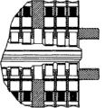
Fig. 5 is the A-A sectional view of the utility model Fig. 4.
Fig. 6 is the local enlarged diagram of Fig. 5.
Fig. 7 is the perspective view of the utility model stator.
Fig. 8 is the perspective view of the utility model rotor.
Fig. 9 is the elevation of the utility model rotor.
Figure 10 is the left view of the utility model rotor.
Figure 11 is the D-D sectional view of the utility model rotor.
Figure 12 is a coding key elevation of the present utility model.
Among the figure: lock core rotor 1, lock core stator 2, coding key 3, fastening screw 4, locating hole 5, locating slot 6, spring cup 7, spring 8, stop pellet shot from a slingshot 9, coding pellet shot from a slingshot 10, the pellet shot from a slingshot hole 11 on the lock core stator, the pellet shot from a slingshot hole 12 on the lock core rotor, radially anti-riot otch 13 on the lock core rotor, the keyhole 14 on the lock core rotor, the coding key tooth 15 on the coding key, anchor point 16 on the lock core stator, the anchor point 17 on the coding key.
The specific embodiment:
Below in conjunction with accompanying drawing the utility model is elaborated:
As Fig. 1, Fig. 2, Fig. 3, Fig. 4, Fig. 5, Fig. 6, Fig. 7, Fig. 8, Fig. 9, Figure 10, Figure 11, shown in Figure 12, among the figure: 1 is lock core rotor, 2 is the lock core stator, 3 is coding key, 4 is the lock core rotor alignment pin, 5 is the locating hole on the lock core rotor, 6 is lock core stator locating slot, 7 is the spring cup in the pellet shot from a slingshot hole on the lock core stator, 8 is the return spring in the pellet shot from a slingshot hole on the lock core stator, 9 is the stop pellet shot from a slingshot in the pellet shot from a slingshot hole on the lock core stator, coding pellet shot from a slingshot on 10 lock core rotors in the pellet shot from a slingshot hole, 11 is the pellet shot from a slingshot hole on the lock core stator, 12 is the step pellet shot from a slingshot hole on the lock core rotor, 13 is the radially anti-riot otch on the lock core rotor, 14 is the keyhole on the lock core rotor, 15 is the coding key tooth on the coding key, 16 is the anchor point on the lock core stator, 17 is the anchor point on the coding key, main member of the present utility model is by lock core rotor 1, lock core stator 2, coding key 3 constitutes, design feature of the present utility model is that lock core rotor 1 is provided with relative two rows and whenever drains into rare 5 step pellet shot from a slingshot hole 12, coding pellet shot from a slingshot 10 is housed in step pellet shot from a slingshot hole 12, lock core rotor 1 is provided with radially anti-riot otch 13, locating hole 5, keyhole 14, lock core rotor 1 cooperates with lock core stator 2, in the locating hole 5 of lock core rotor 1, insert alignment pin 4 by the locating slot on the lock core stator 26, form a lock core rotor and can set the lock core that turns at least 90 degree to rotate, in two row's pellet shot from a slingshot holes of lock core stator 1 and lock core rotor 2 corresponding intercommunications, stop pellet shot from a slingshot 9 return springs 8 spring cups 7 are housed successively in 11 and form a complete lock core.Its concrete function is: coding key 3 is pressed anchor point 16 and 17 and is inserted in the middle of the lock core, coding key tooth 15 and 10 couplings of two scheduling sign indicating number pellets shot from a slingshot, promoting two row's stop pellets shot from a slingshot 9 gets back in the pellet shot from a slingshot hole 11 of lock core stator 2, two scheduling sign indicating number pellets shot from a slingshot 10 become word order under the coupling of coding key tooth 15, height is consistent with the apparent height of lock core rotor 1, in the lock core stator 2 pellet shot from a slingshot holes 10 two row's stop pellet shot from a slingshot 9 also becomes word order under the promotion of coding pellet shot from a slingshot 10, height is consistent with the internal diameter height of lock core stator 2, lock core rotor 1 just can accessiblely rotate like this, and lock core is in released state.When after coding key 3 rotates the position of getting back to anchor point 16 and 17, extracting, on the lock core stator 2 two row stop pellet shot from a slingshot 9 enters under the effect of return spring 8 in two row's pellet shot from a slingshot holes 12 of lock core rotor 1 and docks with two scheduling sign indicating number pellets shot from a slingshot 10 of lock core rotor, stoped lock core rotor 1 to rotate, lock core just is in locking state like this.
Claims (5)
1. a high parameter anti-riot lock core of encoding, by lock core rotor (1), lock core stator (2), coding key (3), coding pellet shot from a slingshot (10), stop pellet shot from a slingshot (9), return spring (8) is formed with spring cup (7), it is characterized in that having on the lock core rotor (1) relative two rows whenever to drain into rare 5 step pellet shot from a slingshot holes (12), coding pellet shot from a slingshot (10) is housed in each pellet shot from a slingshot hole forms the different specific pellet shot from a slingshot combination of height, lock core stator (2) upward and in the two row pellet shot from a slingshot holes (11) of the corresponding intercommunication of lock core rotor (1) is equipped with stop pellet shot from a slingshot (9), return spring (8), spring cup (7) cooperates with lock core rotor (1), coding pellet shot from a slingshot (10) in coding key tooth (14) in the coding key (3) and the lock core rotor (1) forms and cooperates, and radially is provided with otch (13) in the lock core rotor.
2. the high parameter according to claim 1 anti-riot lock core of encoding is characterized in that: on the pellet shot from a slingshot hole of lock core rotor (1) and each corresponding matching intercommunication of lock core stator (2) coding pellet shot from a slingshot (10) stop pellet shot from a slingshot (9) return spring (8) spring cup (7) is housed successively.
3. the high parameter according to claim 1 anti-riot lock core of encoding is characterized in that the pellet shot from a slingshot hole (12) in the described lock core rotor (1) is stepped hole, is used for cooperating with the pellet shot from a slingshot (10) of encoding.
4. the high parameter according to claim 1 anti-riot lock core of encoding is characterized in that latch (4) is arranged on the described lock core rotor (1), has on the lock core stator (2) and the limiting steering groove (6) of latch (4) corresponding matching.
5. the high parameter according to claim 4 anti-riot lock core of encoding is characterized in that described stopper slot (6) can allow lock core rotor (1) set and turn at least 90 degree.
Priority Applications (1)
| Application Number | Priority Date | Filing Date | Title |
|---|---|---|---|
| CN2010201484517U CN201635506U (en) | 2010-03-31 | 2010-03-31 | High-parameter coding anti-riot lock cylinder |
Applications Claiming Priority (1)
| Application Number | Priority Date | Filing Date | Title |
|---|---|---|---|
| CN2010201484517U CN201635506U (en) | 2010-03-31 | 2010-03-31 | High-parameter coding anti-riot lock cylinder |
Publications (1)
| Publication Number | Publication Date |
|---|---|
| CN201635506U true CN201635506U (en) | 2010-11-17 |
Family
ID=43079995
Family Applications (1)
| Application Number | Title | Priority Date | Filing Date |
|---|---|---|---|
| CN2010201484517U Expired - Fee Related CN201635506U (en) | 2010-03-31 | 2010-03-31 | High-parameter coding anti-riot lock cylinder |
Country Status (1)
| Country | Link |
|---|---|
| CN (1) | CN201635506U (en) |
Cited By (1)
| Publication number | Priority date | Publication date | Assignee | Title |
|---|---|---|---|---|
| CN102268936A (en) * | 2010-06-03 | 2011-12-07 | 刘步青 | High-parameter coded anti-violence lock cylinder |
-
2010
- 2010-03-31 CN CN2010201484517U patent/CN201635506U/en not_active Expired - Fee Related
Cited By (1)
| Publication number | Priority date | Publication date | Assignee | Title |
|---|---|---|---|---|
| CN102268936A (en) * | 2010-06-03 | 2011-12-07 | 刘步青 | High-parameter coded anti-violence lock cylinder |
Similar Documents
| Publication | Publication Date | Title |
|---|---|---|
| CN203584033U (en) | Multifunctional anti-theft lock cylinder body and key | |
| CN202544539U (en) | Anti-theft lock capable of being unlocked through flexible key | |
| CN102425339A (en) | Electronic lock capable of being automatically locked | |
| CN105507672B (en) | Intelligent locking and multipolarity lock cylinder | |
| CN106854952B (en) | Composite blade lock core | |
| CN201635506U (en) | High-parameter coding anti-riot lock cylinder | |
| CN201661131U (en) | Door lock | |
| CN202391249U (en) | Novel magnetic control lock cylinder | |
| CN201810047U (en) | High-parameter encoding anti-violence lock cylinder | |
| CN205400266U (en) | Lock body system of unblanking that can be used to electron or mechanical lock | |
| CN202273494U (en) | Lock core structure of multi-core off-axis series connection elastic element lock and key | |
| CN101368461B (en) | Universal lock head and its suited key | |
| CN202391248U (en) | Magnetic control lock cylinder of anti-theft lock | |
| CN102268936A (en) | High-parameter coded anti-violence lock cylinder | |
| CN201169991Y (en) | Triple security lock | |
| CN203441186U (en) | Mechanical lock cylinder | |
| CN202926032U (en) | Tumbler lock head and key thereof | |
| CN201087599Y (en) | Marble of marble idle lock head | |
| CN204552318U (en) | Without the electronic password lock of internal battery | |
| CN205370146U (en) | Intelligence locking and multipolarity pellet shot from a slingshot lock core | |
| CN202627673U (en) | Technical opening prevention lock | |
| CN102704753A (en) | Technical unlocking resisting lockset | |
| CN203308209U (en) | Antitheft lock cylinder | |
| CN203129747U (en) | Matching structure for improving safety and protective performance of lock | |
| CN202380821U (en) | Bidirectional locking blade lock head |
Legal Events
| Date | Code | Title | Description |
|---|---|---|---|
| C14 | Grant of patent or utility model | ||
| GR01 | Patent grant | ||
| C17 | Cessation of patent right | ||
| CF01 | Termination of patent right due to non-payment of annual fee |
Granted publication date: 20101117 Termination date: 20110331 |