A kind of one wire system intelligent dimming switch
Technical field
The utility model belongs to the light regulating technology field of lamp switch, relates to a kind of one wire system intelligent dimming switch.
Background technology
At present, the switch of existing lighting use generally has only two kinds of states of opening and closing, and what existing electronic switch employing power line with distant control function mainly adopted is zero live wire power getting mode, though design is simple like this, but because of single live wire wire laying mode of present main flow, often very inconvenient installation.Some single live wire application and development product, leakage current is very big, does not meet modern society's node environmental protection requirement.
Along with the raising of people's living standard, the continuous progress of science and technology, people are more and more higher to the requirement of household and illumination, not only want to control easily the switch of illuminating lamp, more proposed the requirement to illumination intensity.And will combine with the system of severing in the family, realize satisfying the scene control model that different occasions require, further promote the quality of home environment, build an IKEA environment that the warm heart is comfortable.
The switch inside of tradition light modulation purposes is simple and crude, can only simply reach the purpose of regulating lamplight brightness by the manual adjustments potentiometer.The light modulation of some electronic dimming switch does not possess memory function, has the getting brighter of light that do not possess again of memory function to open the pattern of gradually secretly closing, and can not well satisfy the requirement of people's life to the hommization of lamplight brightness.
Summary of the invention
The utility model regulates that realization brightens gradually or the technical problem of deepening gradually for solving to the illumination of household light fixtures, designed a kind of one wire system intelligent dimming switch, realize the unlatching of light or close by the control silicon controlled angle of flow, and can progressively change the angle of flow and realize that light gets brighter out, dark function of closing gradually.
The utility model realizes that the technical scheme that goal of the invention adopts is, a kind of one wire system intelligent dimming switch, in the circuit structure of switch, comprise power circuit, keyboard-coding circuit and microcontroller circuit, power circuit provides operating voltage for above circuit, also comprise the light modulation executive circuit in the circuit structure, the keyboard-coding circuit is delivered to the manual command signal input of microcontroller circuit, after microcontroller circuit identification is handled control signal corresponding is sent to the input of light modulation executive circuit, the light modulation executive circuit is by the voltage of regulation and control conversion output, realize the adjustment of load dissipation power.
The operation principle of this circuit is: the keyboard-coding circuit sends to microcontroller circuit with the command signal of corresponding function, microcontroller circuit transmits control signal to the light modulation executive circuit after according to the needed function of user command signal being handled, the light modulation executive circuit carries out internal regulation according to user's function, realizes bright gradually, dark, the function of opening or turn-offing gradually.
The beneficial effects of the utility model are intensity of lights that single-chip microcomputer is regulated can remember the user automatically and use the time, the light opening and closing have realized soft start and soft shutoff, make the function that light has been realized getting brighter out and gradually secretly gone out, prolonged the useful life of light fixture, eliminated human eye because the vision injury that causes is opened or closed to light moment.
Below in conjunction with accompanying drawing the utility model is elaborated.
Description of drawings
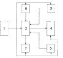
Fig. 1 is a circuit block diagram of the present utility model.
Fig. 2 is microcontroller circuit embodiment of the present utility model.
Fig. 3 is light modulation executive circuit embodiment of the present utility model.
Fig. 4 is civil power phase detecting circuit embodiment of the present utility model.
Fig. 5 is infrared receiving circuit embodiment of the present utility model.
Fig. 6 is a keyboard-coding circuit embodiments of the present utility model.
In the accompanying drawing, the 1st, power circuit, the 2nd, microcontroller circuit, the 3rd, keyboard-coding circuit, the 4th, light modulation executive circuit, the 5th, civil power phase detecting circuit, the 6th, infrared receiving circuit, the 7th, indicator light circuit, R1-R13 are resistance, C1-C8 is an electric capacity, and ATMEGA48-32 is a single-chip microcomputer, and Q1, Q2, Q3 are triodes, D1-D5 is a diode, and T is a controllable silicon, and K1, K2 are buttons, RX is a chip, and ANT is an antenna, and L is an inductance.
Embodiment
Referring to Fig. 1, a kind of one wire system intelligent dimming switch, in the circuit structure of switch, comprise power circuit, keyboard-coding circuit and microcontroller circuit, power circuit provides operating voltage for above circuit, also comprise light modulation executive circuit 4 in the circuit structure, keyboard-coding circuit 3 is delivered to the manual command signal input of microcontroller circuit 2, after microcontroller circuit 2 identifications are handled control signal corresponding is sent to the input of light modulation executive circuit 4, light modulation executive circuit 4 is by the voltage of regulation and control conversion output, the adjustment of realization load dissipation power.Keyboard-coding circuit 3 sends to microcontroller circuit 2 with the command signal of corresponding function, microcontroller circuit 2 transmits control signal to light modulation executive circuit 4 after according to the needed function of user command signal being handled, light modulation executive circuit 4 carries out internal regulation according to user's function, realizes bright gradually, dark, the function of opening or turn-offing gradually.
In order to realize the remote-controlled intelligent dimming function, also include infrared receiving circuit 6 in the above-mentioned circuit structure, be sent to the input of microcontroller circuit 2 after the infrared encoded signal that infrared receiving circuit 6 is sent remote controller is handled, after microcontroller circuit 2 identifications are handled control signal be sent to the input of light modulation executive circuit 4.Can be between remote controller and the switch by study realize the control corresponding function to sign indicating number, the user can carry out personal settings according to the needs of oneself.The light opening and closing have realized soft start and soft shutoff, make the function that light has been realized getting brighter out and gradually secretly gone out, and have prolonged the useful life of light fixture, have eliminated human eye because the vision injury that causes is opened or closed to light moment.
In order to solve when line voltage is unstable the protection light fixture and then to increase the service life; also comprise civil power phase detecting circuit 5 in the circuit structure of stating; electricity phase detecting circuit 5 will detect the input that voltage signal on the civil power is delivered to microcontroller circuit 2, after microcontroller circuit 2 computings pressure regulation command signal of correspondence be transmitted the input of delivering to light modulation executive circuit 4.
Above-mentioned power circuit 1 is exported the dc supply signal with AC signal and is provided operating voltage for above functional circuit unit after transformer step-down, diode rectification, capacitor filtering and voltage-stabiliser tube voltage stabilizing.
Above-mentioned microcontroller circuit 2 comprises single chip computer AT MEGA48-32 and peripheral matched Resistor-Capacitor Unit, single chip computer AT MEGA48-32 receives the sampled signal that command coding signal that keyboard-coding circuit 3 sends, infrared encoded signal that infrared receiving circuit 6 is sent and civil power phase detecting circuit 5 are sent, and outputs control signals to the input of light modulation executive circuit 4 after the computing.
Above-mentioned light modulation executive circuit 4 comprises amplifying circuit, controllable silicon T and the supporting diode of being made up of triode Q1 and supporting resistive element, triode Q1 base stage receives the control signal that single chip computer AT MEGA48-32 sends, and control controllable silicon T changes the angle of flow gradually and realizes that light opens gradually or close gradually after the processing and amplifying.
Above-mentioned civil power phase detecting circuit 5 comprises diode D1 and supporting current-limiting resistance R1, capacitor C 3 and diode D2, and civil power phase detecting circuit 5 is gone up the detection input that the positive half cycle ac pulse voltage signal that forms is delivered to single chip computer AT MEGA48-32 with diode D1.Civil power phase detecting circuit 6 is connected with microprocessor, the diode D2 that civil power phase detecting circuit 5 links to each other with load by inside obtains the discernible voltage of microprocessor, be added in the alternating voltage at load two ends, introduce by load place, through current-limiting resistance R1, on diode, form positive half cycle and exchange pulsating voltage, deliver to the phase-detection input of microprocessor.When the voltage on the diode D1 surpassed set point, processor can produce external interrupt, and as the pulse of benchmark output brightness adjustment control.According to corresponding situation, the unlatching of control dimmer switch or close, and to the adjusting of lamplight brightness.
Amplifying circuit and supporting on every side Resistor-Capacitor Unit that above-mentioned infrared receiving circuit 6 comprises antenna ANT, chip RX, is made up of triode Q2 and supporting Resistor-Capacitor Unit, antenna ANT receives the infrared encoded signal that remote controller is sent, and delivers to the input of single chip computer AT MEGA48-32 after chip RX and amplifying circuit processing.
Also be provided with the indicator light circuit 7 that switch carries out light modulation work in the circuit structure of last switch, the indicator light in the indicator light circuit 7 is respectively by microcontroller circuit 2 controls.Indicator light circuit 7 is connected with microcontroller circuit 2, and the result that microcontroller circuit 2 is carried out according to program makes corresponding indication by the operating state of 7 pairs of switches of indicator light circuit.
The utility model has kept the manual function of conventional switch, can open or close light by the button on the panel, long can realize adjusting to lamplight brightness by button, keyboard-coding circuit 3 detects the action of button, passing the signal to microcontroller circuit 2 handles, microprocessor is controlled the switch of light, the adjusting of light and shade according to the corresponding instruction executive program.When button is pinned when being no more than for 10 seconds for a long time, bright-dark degree that can manual adjustments light reaches the illumination requirement of user's request.When button continued to pin above 10 seconds, opening the light promptly entered remote control to the sign indicating number learning state, and can press remote controller key this moment, behind the learning success, and the indicator light flicker twice in the indicator light circuit 7, indication study is successful to sign indicating number.
The utility model has the advantages that: the brightness of light can by manually and the remote control dual mode regulate the lamplight brightness that the utility model can automatic Memory user adjusting. Can automatically be adjusted to lamplight brightness that user last time arranged when opening next time, solved the defective that a lot of dimmer switch do not possess memory function. The utlity model has high reliability, high sensitivity, easy to use, economical and practical characteristics, for people's life brings more comfortablely, human nature, convenient IKEA are enjoyed more.