CN201606842U - Strip-shaped lamp connector - Google Patents
Strip-shaped lamp connector Download PDFInfo
- Publication number
- CN201606842U CN201606842U CN2010201083475U CN201020108347U CN201606842U CN 201606842 U CN201606842 U CN 201606842U CN 2010201083475 U CN2010201083475 U CN 2010201083475U CN 201020108347 U CN201020108347 U CN 201020108347U CN 201606842 U CN201606842 U CN 201606842U
- Authority
- CN
- China
- Prior art keywords
- strip light
- strip
- end cap
- contact pin
- shank
- Prior art date
- Legal status (The legal status is an assumption and is not a legal conclusion. Google has not performed a legal analysis and makes no representation as to the accuracy of the status listed.)
- Expired - Fee Related
Links
Images


Abstract
The utility model discloses a strip-shaped lamp connector, which comprises a first end cover having a chamber matched in shape with a strip-shaped clamp, an inserting pin arranged on the bottom of the chamber and connected with the copper stranded cable in the strip-shaped clamp, wherein the inserting pin is further connected with a conducting wire having an end cover extending outwards. By arranging the strip-shaped lamp connecter at the end part of a strip-shaped lamp and connecting the external power supplies of two strip-shaped lamps via the conducting wire extending outside the end cover, the strip-shaped lamps are prolonged in length, and the same time, the purpose of using the power supply of one strip-shaped lamp is realized; as the conducting wire extends outside the end cover, the two interconnected strip-shaped lamps provide a buffering for the inserting pin and the copper stranded cable in installation to avoid the bad contact between the inserting pin and the copper stranded cable. The utility model has the advantages of simple structure, firm connection and convenient use.
Description
[technical field]
The utility model relates to a kind of connector, especially relates to a kind of strip light connector.
[background technology]
Strip light is finished by automated machine production, and the chances are about 1 meter is a unit for the interior lamp string of its fluorescent tube, can cut randomly between each unit, and any end of the strip light of cutting adds that the power supply connector can light.Producing strip light for finished product by after detecting, is that a volume packing is sold with 50 meters or 100 meters often when curling packing.And when project installation and use, usually need strip light be cut short the consumption of saving bar shaped to reach according to engineering demand, and the power supply that needs to prolong the length of strip light sometimes and use same strip light then needs a connector that prolongs strip light length to achieve the goal this moment.
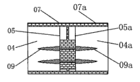
Traditional strip light connector is with reference to Fig. 1, shown in Figure 2, comprise the end cap 07, the 07a that lean against to one by two, have cavity 04,04a in end cap 07, the 07a with strip light profile coupling, be arranged on last copper stranded conductor quantity and corresponding contact pin 09, the 09a in position with strip light of diapire 05, the 05a of end cap 07,07a, the contact pin 09 on the same straight line, 09a mutual conduction.Its strip light one end is installed in connector wherein in the end cap 07, one end of another strip light is installed in another end cap 07a of this connector, the diapire 05 of end cap 07,07a, last corresponding respectively contact pin 09, the 09a that is provided with of 05a are electrically connected with the strip light copper stranded conductor, do not show in the accompanying drawing, thereby the unlimited prolongation that realizes strip light also reaches the purpose of using same strip light power supply simultaneously to satisfy different project installation and application.But, above-mentioned connector is applied in project installation and the use in the future has a lot of defectives, when the strip light that connector is installed is carried out project installation, occur easily that connector and strip light come off or the phenomenon of contact pin and copper stranded conductor loose contact, cause the difficulty that increases project installation, influence the project installation progress.In use in the future, because strip light is to adopt the soft plastic material to make, be easy to the phenomenon that occurs expanding with heat and contract with cold, cause the bar shaped bar of installing and using connector to occur and strip light glue falls or the phenomenon of contact pin and copper stranded conductor loose contact happens occasionally.Cause strip light to open circuit and influence the decorative effect of whole ornament lamp.
[utility model content]
The technical problems to be solved in the utility model provide a kind of cost low, be connected firmly, strip light connector easy to use.
In order to solve the problems of the technologies described above, the technical solution adopted in the utility model is: a kind of strip light connector, it is characterized in that, comprise first end cap, first end cap has the cavity with strip light profile coupling, be provided with the contact pin that is connected with copper twisted wire in the strip light in the bottom of described cavity, described contact pin also is connected with the lead that extends outside end cap.
The beneficial effects of the utility model are: owing to be provided with the contact pin that is connected with copper stranded conductor in the strip light in the bottom of end cap cavity, also be connected with the lead of extension outside end cap on described contact pin.The utility model is installed in the end of strip light, to in twos by the lead that extends outside end cap, the external power cord of strip light couples together, use the purpose of same strip light power supply when can realize prolonging strip light length, owing to outside end cap, be extended with lead, interconnective two strip light can make contact pin and copper twisted wire obtain buffering when mounted, avoid the phenomenon of contact pin and the loose contact of copper twisted wire to take place.That the utility model also has is simple in structure, be connected firmly, advantage easy to use.
Preferably, also comprise second end cap, described second end cap has the cavity with strip light profile coupling, and described cavity bottom is provided with the contact pin that is connected with copper twisted wire in the strip light, and the lead of first end cap directly is electrically connected with the contact pin of this second end cap.
Preferably, described contact pin comprises pedestal, and with the shank of pedestal integrative-structure and be connected needle point on the described shank, described shank is littler than the diameter of described pedestal, and described pedestal is fixed on the diapire of described housing by injection moulding.
Preferably, described shank diminishes gradually along described needle point direction, also is provided with a plurality of fins that prevent that contact pin from skidding off from copper stranded conductor on described shank.
Preferably, described fin is around the axial setting of described shank.
[description of drawings]
Below in conjunction with accompanying drawing the utility model is described in further detail.
Fig. 1 is the structural representation of conventional strip lamp connector.
Fig. 2 is the cutaway view of conventional strip lamp connector shown in Figure 1.
Fig. 3 is a structural representation of the present utility model.
Fig. 4 is another structural representation of the present utility model.
Fig. 5 is installed in structural representation on the strip light for the utility model.
Fig. 6 is the amplification plane figure of A part shown in Figure 5.
Fig. 7 is a B-B cutaway view shown in Figure 6.
Fig. 8 is the structure for amplifying schematic diagram of C part shown in Figure 7.
Fig. 9 is the structural representation of the utility model contact pin.
[specific embodiment]
With reference to accompanying drawing 3, the utility model comprises first end cap 10, the first end cap tool 10 has the cavity 15 with strip light profile coupling, is provided with the contact pin 12 that is connected with copper twisted wire in the strip light in the bottom 15 of described cavity 14, and described contact pin 12 also is connected with the lead 16 of extension outside end cap 10.Also comprise the second end cap 10a, the described second end cap 10a has the cavity 14a with strip light profile coupling, the bottom 15a of described cavity 14a is provided with the contact pin 12a that is connected with copper twisted wire in the strip light, the lead 16 of first end cap 10 directly is electrically connected with the contact pin 12a of this second end cap 10a, as shown in Figure 4.
Shown in accompanying drawing 3-8, comprise attaching plug 19, first strip light 18, the second strip light 18a, the head end of first strip light 18 is connected with attaching plug 19, first strip light 18 is electrically connected with the connector 100a that the connector 100 that the second strip light 18a installs by the tail end of first strip light 18 is connected with the second strip light 18a head end, tail end at the second strip light 18a also is equipped with connector 100b, described connector 100,100a, 100b comprises first end cap 10, in first end cap 10, be provided with and first strip light 18, the cavity 14 of second strip light 18a profile coupling, at connector 100,100a is provided with two contact pins 12, connector 100, last two contact pins 12 of 100a respectively with first strip light 18, the position correspondence of two copper stranded conductors 20 in the second strip light 18a, outer setting at first end cap 10 has the lead 16 that is connected with the second end cap 10a, described lead 16 is electrically connected with the contact pin 12a of setting in the described second end cap 10a, as shown in Figure 4.Two contact pins 12 that are provided with in the described connector 100 insert in the copper stranded conductor 20 of first strip light 18, and two contact pins 12 that are provided with in described connector 100a, the 100b insert respectively in the two ends copper stranded conductor 20 of the second strip light 18a, as Fig. 5, shown in Figure 7.The positive pole of the positive pole of the lead 16 of connector 100 and the lead 16 of connector 100a is electrically connected, be nested with a waterproof cover 24 on two anodal connector, the negative electricity of the negative pole of the lead 16 of connector 100 and the lead 16 of end cap 100a links together, also be nested with a waterproof cover 24 on two negative pole connector, shown in Fig. 5,7.
Above-mentioned contact pin 12 comprises pedestal 121, with the shank 124 of pedestal 12 integrative-structures and be connected needle point 122 on the shank 124, described shank 124 is littler than the diameter of described pedestal 121, and as shown in Figure 9, described pedestal 121 is fixed on the diapire 15 of described end cap 10 by injection moulding.Described shank 124 diminishes gradually along described needle point 122 directions, also is provided with a plurality of fins 123 that prevent that contact pin 12 from skidding off from copper stranded conductor 20 on described shank 124, and described fin 123 is around the axial setting of described shank 124.Design can be inserted into contact pin 12 in the copper stranded conductor 20 smoothly like this, can prevent that again contact pin 12 from skidding off simultaneously in copper stranded conductor 20, and design can increase the coefficient of friction of contact pin 12 and copper stranded conductor 20 greatly like this, prevents that connector from coming off from the end of strip light.Above-mentioned copper stranded conductor 20 is made of many copper wire strands together.Described lead 16 is an enamel-covered wire, and described enamel-covered wire is exactly that the bare conductor outside is surrounded by one deck insulation sheath, and its insulation sheath can be rubber crust or plastic peel etc., wherein, with that section leads 16 of contact pin 12 connecting portions for removing the bare conductor of crust.
Owing to be provided with the contact pin that is connected with copper stranded conductor in the strip light in the bottom of end cap cavity, on described contact pin, also be connected with the lead of extension outside end cap.The utility model is installed in the end of strip light, to in twos by the lead that extends outside end cap, the external power cord of strip light couples together, use the purpose of same strip light power supply when can realize prolonging strip light length, owing to outside end cap, be extended with lead, interconnective two strip light can make contact pin and copper twisted wire obtain buffering when mounted, avoid the phenomenon of contact pin and the loose contact of copper twisted wire to take place.That the utility model also has is simple in structure, be connected firmly, advantage easy to use.
The above is all so that the utility model conveniently to be described, in the spiritual category that does not break away from the utility model creation, the various simple covert and modification that those skilled in the art did of being familiar with this technology still belongs to protection domain of the present utility model.
Claims (5)
1. strip light connector, it is characterized in that: comprise first end cap, first end cap has the cavity with strip light profile coupling, is provided with the contact pin that is connected with copper twisted wire in the strip light in the bottom of described cavity, and described contact pin also is connected with the lead of extension outside end cap.
2. strip light connector according to claim 1, it is characterized in that: also comprise second end cap, described second end cap has the cavity with strip light profile coupling, described cavity bottom is provided with the contact pin that is connected with copper twisted wire in the strip light, and the lead of first end cap directly is electrically connected with the contact pin of this second end cap.
3. strip light connector according to claim 1 and 2, it is characterized in that: described contact pin comprises pedestal, with the shank of pedestal integrative-structure and be connected needle point on the described shank, described shank is littler than the diameter of described pedestal, and described pedestal is fixed on the diapire of described housing by injection moulding.
4. strip light connector according to claim 3 is characterized in that: described shank diminishes gradually along described needle point direction, also is provided with a plurality of fins that prevent that contact pin from skidding off from copper stranded conductor on described shank.
5. strip light connector according to claim 4, its special sheet is: described fin is around the axial setting of described shank.
Priority Applications (1)
| Application Number | Priority Date | Filing Date | Title |
|---|---|---|---|
| CN2010201083475U CN201606842U (en) | 2010-02-02 | 2010-02-02 | Strip-shaped lamp connector |
Applications Claiming Priority (1)
| Application Number | Priority Date | Filing Date | Title |
|---|---|---|---|
| CN2010201083475U CN201606842U (en) | 2010-02-02 | 2010-02-02 | Strip-shaped lamp connector |
Publications (1)
| Publication Number | Publication Date |
|---|---|
| CN201606842U true CN201606842U (en) | 2010-10-13 |
Family
ID=42951548
Family Applications (1)
| Application Number | Title | Priority Date | Filing Date |
|---|---|---|---|
| CN2010201083475U Expired - Fee Related CN201606842U (en) | 2010-02-02 | 2010-02-02 | Strip-shaped lamp connector |
Country Status (1)
| Country | Link |
|---|---|
| CN (1) | CN201606842U (en) |
Cited By (2)
| Publication number | Priority date | Publication date | Assignee | Title |
|---|---|---|---|---|
| CN106382524A (en) * | 2016-10-17 | 2017-02-08 | 广东欧曼科技股份有限公司 | Dark spot-free lamp belt connector and lamp using same |
| CN107091465A (en) * | 2016-02-16 | 2017-08-25 | 鹤山市银雨照明有限公司 | A kind of flexible lamp strip joint design |
-
2010
- 2010-02-02 CN CN2010201083475U patent/CN201606842U/en not_active Expired - Fee Related
Cited By (3)
| Publication number | Priority date | Publication date | Assignee | Title |
|---|---|---|---|---|
| CN107091465A (en) * | 2016-02-16 | 2017-08-25 | 鹤山市银雨照明有限公司 | A kind of flexible lamp strip joint design |
| CN107091465B (en) * | 2016-02-16 | 2020-02-07 | 广东同方灯饰有限公司 | Flexible light bar joint structure |
| CN106382524A (en) * | 2016-10-17 | 2017-02-08 | 广东欧曼科技股份有限公司 | Dark spot-free lamp belt connector and lamp using same |
Similar Documents
| Publication | Publication Date | Title |
|---|---|---|
| WO2008058481A1 (en) | A decorative lamp string | |
| CN203339618U (en) | Suspended wire clamp | |
| CN201606842U (en) | Strip-shaped lamp connector | |
| CN201075311Y (en) | Electric wire cable | |
| CN204407535U (en) | One exempts from wire stripping deconcentrator | |
| CN201335326Y (en) | Decorative lamp | |
| CN205026480U (en) | Tensile decorative chain | |
| CN210074226U (en) | Metal conductor suitable for switch wiring | |
| CN103474611A (en) | Battery pack | |
| CN210383391U (en) | Power supply guide rail structure | |
| CN203192444U (en) | Solar photovoltaic wire | |
| CN203300919U (en) | Power supply connector | |
| CN202977934U (en) | Signal output harness | |
| CN202872005U (en) | Energy-saving electrical connector | |
| CN205141230U (en) | Plug connector is connected to insulating sheath and electricity that has this insulating sheath | |
| CN204696311U (en) | A kind of environmental protection and energy saving power cord plug | |
| CN201153163Y (en) | Connector | |
| CN214094092U (en) | Hose lamp | |
| CN101135422A (en) | Magic colorful light | |
| CN204045746U (en) | A kind of binding post | |
| CN202443787U (en) | Parallel coaxial cable | |
| CN204068096U (en) | A kind of cable eyelet strip | |
| CN203839638U (en) | LED lamp wire material connector | |
| CN111180108B (en) | Conductive tube | |
| CN204005450U (en) | Connect lamp string easily |
Legal Events
| Date | Code | Title | Description |
|---|---|---|---|
| C14 | Grant of patent or utility model | ||
| GR01 | Patent grant | ||
| C17 | Cessation of patent right | ||
| CF01 | Termination of patent right due to non-payment of annual fee |
Granted publication date: 20101013 Termination date: 20120202 |