CN201530687U - Maintenance cantilever crane of tower crane - Google Patents
Maintenance cantilever crane of tower crane Download PDFInfo
- Publication number
- CN201530687U CN201530687U CN2009201991909U CN200920199190U CN201530687U CN 201530687 U CN201530687 U CN 201530687U CN 2009201991909 U CN2009201991909 U CN 2009201991909U CN 200920199190 U CN200920199190 U CN 200920199190U CN 201530687 U CN201530687 U CN 201530687U
- Authority
- CN
- China
- Prior art keywords
- pulley
- cantilever
- bearing pin
- strut
- spring cotter
- Prior art date
- Legal status (The legal status is an assumption and is not a legal conclusion. Google has not performed a legal analysis and makes no representation as to the accuracy of the status listed.)
- Expired - Fee Related
Links
Images


Abstract
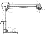
The utility model relates to a maintenance cantilever crane of a tower crane, which is characterized in that the maintenance cantilever crane comprises a windlass, pulleys, a cantilever crane mounting base, a stay bar, a cantilever beam, a pulley case, a pulley frame, a wedge sleeve, a wedge, a pin shaft, a pin shaft, cotter pins, rollers and traveling wheels, wherein the cantilever crane mounting base is fixed on a balance arm; one pulley is mounted in the cantilever crane mounting base; the windlass is mounted on the cantilever crane mounting base; the stay bar is mounted in the cantilever crane mounting base; another pulley is mounted in the stay bar; two rollers are mounted in two positions close to the lower surface first of the stay bar; the cantilever beam is mounted on the rollers of the stay bar; the other two rollers are mounted on the stay bar, and the pin shaft is inserted into the stay bar; four traveling wheels are mounted on a pulley case; the pulley case provided with the four traveling wheels is mounted on the cantilever beam; another pulley is mounted on the pulley case; another pulley is mounted on the pulley frame, and then the pulley frame is mounted on the pulley case; and a steel wire rope in the windlass passes through the pulley in the cantilever crane mounting base, reaches the pulley in the stay bar, reaches the pulley in the pulley case, then reaches the pulley in the pulley frame, and finally, is fixed on the pulley case through the wedge and the wedge sleeve 8.
Description
Affiliated technical field
The utility model is that the maintenance cantilever of tower crane hangs, and lifting mechanism parts, torque arm mechanism components and the electric cabinet etc. that can utilize cantilever to hang will will to keep in repair on the tower machine hang ground.
Background technology
The maintenance cantilever of at present domestic tower crane hangs and can only rotate and luffing, but when being hung in rotation, cantilever is easy to run into miscellaneous part, such as equilibrium arm pull bar etc., so just can not rotate by 360 degree, cause some parts can hang less than, thereby such cantilever hangs the effect of just not playing lifting fully.
Summary of the invention
When being hung in rotation, above-mentioned cantilever is easy to run into miscellaneous part in order to overcome, the utility model re-constructs the structural shape of cantilever beam, change original fixed boom beam into cantilever beam and 4 synthetic movable boom beams of roller set, cantilever is hung can both freedom 360 be rotated, and gives full play to the effect of its lifting.
The technical scheme that its technical matters that solves the utility model adopts is:
The maintenance cantilever of tower crane hangs, the maintenance cantilever of tower crane hangs, and it comprises that winch, pulley, cantilever hang mount pad, strut, cantilever beam, pulley casing, pulley yoke, cover of wedge, wedge, bearing pin, bearing pin, spring cotter, roller, travelling wheel and cantilever hung mount pad be fixed on the equilibrium arm; Pulley is contained in cantilever and hangs in the mount pad, connects with bearing pin, plugs spring cotter; Winch is installed in cantilever and hangs on the mount pad; Strut is installed in cantilever and hangs in the mount pad; Pulley is installed in the strut, connects with bearing pin, plugs spring cotter; Earlier two rollers are installed in strut by on two following positions, connect, plug spring cotter with bearing pin; Cantilever beam is installed on the roller of strut; 2 rollers are installed in two positions above the strut, connect, plug spring cotter, bearing pin is inserted in the strut, plug spring cotter, cantilever beam is not slided on strut with bearing pin; Four travelling wheels are installed on the pulley casing; The pulley casing that four travelling wheels have been installed is installed on the cantilever beam; Pulley is installed on the pulley casing, connects with bearing pin 11, plugs spring cotter; , earlier pulley is installed on the pulley yoke, connect with bearing pin, plug spring cotter, again pulley yoke is installed on the pulley casing, connect with bearing pin, plug spring cotter; Steel rope in the winch is hung the mount pad middle pulley by cantilever, arrive the strut middle pulley again, arrive the pulley casing middle pulley again, arrive the pulley yoke middle pulley again, be fixed on the pulley casing with wedge and cover of wedge at last.
The utility model re-constructs the structural shape of cantilever beam, changes original fixed boom beam into cantilever beam and 4 synthetic movable boom beams of roller set, and cantilever is hung can both freedom 360 be rotated, and gives full play to the effect of its lifting.
Description of drawings
Fig. 1 is the utility model structural representation;
Fig. 2 is the A-A cut-away view;
Fig. 3 is the B-B cut-away view;
Fig. 4 is the C-C cut-away view;
Fig. 5 is the D-D cut-away view.
Icon is: 1, winch 2 pulleys 3, cantilever hang mount pad 4 struts 5, cantilever beam 6, pulley casing 7, pulley yoke 8, cover of wedge 9 wedges 10, bearing pin 11, bearing pin 12, spring cotter 13, roller 14, travelling wheel.
The specific embodiment
Further specify below in conjunction with accompanying drawing:
Shown in Fig. 1~5, the maintenance cantilever of tower crane hangs, it comprises that winch 1, pulley 2, cantilever hang mount pad 3, strut 4, cantilever beam 5, pulley casing 6, pulley yoke 7, cover of wedge 8, wedge 9, bearing pin, bearing pin 11, spring cotter, roller, travelling wheel 14, cantilever is hung mount pad 3 be fixed on (welding is fixing) on the equilibrium arm; Pulley 2 is installed in cantilever and hangs in the mount pad 4, connects with bearing pin 11, plugs spring cotter 14; Winch 1 is installed in cantilever and hangs on the mount pad 3; Strut 4 is installed in cantilever and hangs in the mount pad 4; Pulley 2 is installed in the strut 4, connects with bearing pin 11, plugs spring cotter 14; Two rollers are installed in strut 4 by on two following positions, connect, plug spring cotter 14 with bearing pin 11; Cantilever beam 5 is installed on the roller of strut 4; 2 rollers 13 are installed in two positions above the strut 4, connect, plug spring cotter 14, bearing pin 9 is inserted in the struts, plug spring cotter 14, cantilever beam 5 is not slided on strut 4 with bearing pin 11; Four travelling wheels are installed on the pulley casing 6; The pulley casing 4 that four travelling wheels have been installed is installed on the cantilever beam 5; Pulley 2 is installed on the pulley casing 6, connects with bearing pin 11, plugs spring cotter 14; Earlier pulley 2 is installed on the pulley yoke 7, connects, plug spring cotter 14, again pulley yoke 7 is installed on the pulley casing 6, connect, plug spring cotter 14 with bearing pin 10 with bearing pin 11; Steel rope in the winch 1 is hung mount pad 3 middle pulleys 2 by cantilever, arrive strut 4 middle pulleys 2 again, arrive pulley casing 6 middle pulleys 2 again, arrive pulley yoke 7 middle pulleys 2 again, be fixed on the pulley casing 6 with wedge 9 and cover of wedge 8 at last.
Working process is: in the time will lifting, the bearing pin on the pulley casing 6 10 is not shown, pulley yoke can be moved up and down.When wanting inside and outside when mobile, the direct pull pulley casing moves.Run into obstacle in rotation, the bearing pin on the strut 4 10 is up to, cantilever beam just can stretch, the cut-through thing.So just can reach 360 degree rotations.
At last, should be pointed out that above embodiment only is the more representational example of the utility model.Obviously, the technical solution of the utility model is not limited to the foregoing description, and many distortion can also be arranged.All distortion that those of ordinary skill in the art can directly derive or associate from the disclosed content of the utility model all should be thought protection domain of the present utility model.
Claims (1)
1. the maintenance cantilever of tower crane hangs, it is characterized in that: comprise that winch, pulley, cantilever hang mount pad, strut, cantilever beam, pulley casing, pulley yoke, cover of wedge, wedge, bearing pin, bearing pin, spring cotter, roller, travelling wheel, cantilever is hung mount pad to be fixed on the equilibrium arm, pulley is contained in cantilever and hangs in the mount pad, connect with bearing pin, plug spring cotter; Winch is installed in cantilever and hangs on the mount pad; Strut is installed in cantilever and hangs in the mount pad; Pulley is installed in the strut, connects with bearing pin, plugs spring cotter; Earlier two rollers are installed in strut by on two following positions, connect, plug spring cotter with bearing pin; Cantilever beam is installed on the roller of strut; 2 rollers are installed in two positions above the strut, connect, plug spring cotter, bearing pin is inserted in the strut, plug spring cotter with bearing pin; Four travelling wheels are installed on the pulley casing; The pulley casing that four travelling wheels have been installed is installed on the cantilever beam; Pulley is installed on the pulley casing, connects with bearing pin (11), plugs spring cotter; Earlier pulley is installed on the pulley yoke, connects, plug spring cotter, again pulley yoke is installed on the pulley casing, connect, plug spring cotter with bearing pin with bearing pin; Steel rope in the winch is hung the mount pad middle pulley by cantilever, arrive the strut middle pulley again, arrive the pulley casing middle pulley again, arrive the pulley yoke middle pulley again, use wedge and cover of wedge (8) to be fixed on the pulley casing at last.
Priority Applications (1)
| Application Number | Priority Date | Filing Date | Title |
|---|---|---|---|
| CN2009201991909U CN201530687U (en) | 2009-10-22 | 2009-10-22 | Maintenance cantilever crane of tower crane |
Applications Claiming Priority (1)
| Application Number | Priority Date | Filing Date | Title |
|---|---|---|---|
| CN2009201991909U CN201530687U (en) | 2009-10-22 | 2009-10-22 | Maintenance cantilever crane of tower crane |
Publications (1)
| Publication Number | Publication Date |
|---|---|
| CN201530687U true CN201530687U (en) | 2010-07-21 |
Family
ID=42526092
Family Applications (1)
| Application Number | Title | Priority Date | Filing Date |
|---|---|---|---|
| CN2009201991909U Expired - Fee Related CN201530687U (en) | 2009-10-22 | 2009-10-22 | Maintenance cantilever crane of tower crane |
Country Status (1)
| Country | Link |
|---|---|
| CN (1) | CN201530687U (en) |
Cited By (3)
| Publication number | Priority date | Publication date | Assignee | Title |
|---|---|---|---|---|
| CN103101848A (en) * | 2011-11-15 | 2013-05-15 | 浙江虎霸建设机械有限公司 | Portable maintenance cantilever hoist of tower crane |
| CN103722330A (en) * | 2013-12-12 | 2014-04-16 | 中联重科股份有限公司 | Assembly welding tool of installation bases and connecting method of lifting mechanism and balance arm |
| CN108190767A (en) * | 2018-03-05 | 2018-06-22 | 无锡石油化工起重机有限公司 | The rotation arm of the mobile lubrication nozzle of installation |
-
2009
- 2009-10-22 CN CN2009201991909U patent/CN201530687U/en not_active Expired - Fee Related
Cited By (4)
| Publication number | Priority date | Publication date | Assignee | Title |
|---|---|---|---|---|
| CN103101848A (en) * | 2011-11-15 | 2013-05-15 | 浙江虎霸建设机械有限公司 | Portable maintenance cantilever hoist of tower crane |
| CN103722330A (en) * | 2013-12-12 | 2014-04-16 | 中联重科股份有限公司 | Assembly welding tool of installation bases and connecting method of lifting mechanism and balance arm |
| CN103722330B (en) * | 2013-12-12 | 2015-11-11 | 中联重科股份有限公司 | The method of attachment of joining mounted welder and lifting mechanism and counter-jib of mount pad |
| CN108190767A (en) * | 2018-03-05 | 2018-06-22 | 无锡石油化工起重机有限公司 | The rotation arm of the mobile lubrication nozzle of installation |
Similar Documents
| Publication | Publication Date | Title |
|---|---|---|
| CN207129869U (en) | A kind of crane equipment that lifting force is obtained by counterweight | |
| CN205653091U (en) | Many davits tower crane | |
| CN201530687U (en) | Maintenance cantilever crane of tower crane | |
| CN207418151U (en) | A kind of multifunctional building crane | |
| CN202440231U (en) | Gantry crane lifting hook device | |
| CN202575785U (en) | Portal crane and four-connecting-rod system thereof | |
| CN202449763U (en) | Simple pneumatic crane | |
| CN202465078U (en) | Hoisting mechanism of crane | |
| CN204237468U (en) | A kind of arm tower crane | |
| CN202465117U (en) | Suspending arm of crane | |
| CN204848083U (en) | European style is conductor rope wheel for electric block | |
| CN202449728U (en) | Double-pulley lifting hook device of gantry crane | |
| CN202090673U (en) | Combined holding pole used for hoisting tower pole | |
| CN202011702U (en) | Chain type cable supporting device | |
| CN202429891U (en) | Crane hook device | |
| CN102030272A (en) | Building equipment hoisting device | |
| CN202465098U (en) | Single-beam gantry crane with V-shaped support legs | |
| CN102139835B (en) | Electric crane with limiting device | |
| CN205472332U (en) | Rotatable simple and easy armful of pole hoist | |
| CN215797905U (en) | Lifting appliance convenient and fast to disassemble and assemble vertical mill roller sleeve | |
| CN203568719U (en) | Hoisting mechanism of asphalt pavement maintenance truck | |
| CN210944618U (en) | Counter weight self-lifting device for crane | |
| CN203306947U (en) | Luffing mechanism of luffing jib tower crane and luffing jib tower crane | |
| CN201901550U (en) | Electric crane with limiting device | |
| CN202912595U (en) | Double-suspension arm balance crane of crane |
Legal Events
| Date | Code | Title | Description |
|---|---|---|---|
| C14 | Grant of patent or utility model | ||
| GR01 | Patent grant | ||
| CF01 | Termination of patent right due to non-payment of annual fee |
Granted publication date: 20100721 Termination date: 20141022 |
|
| EXPY | Termination of patent right or utility model |