CN201488039U - Commercial infrared efficient energy-saving stove - Google Patents
Commercial infrared efficient energy-saving stove Download PDFInfo
- Publication number
- CN201488039U CN201488039U CN2009201764318U CN200920176431U CN201488039U CN 201488039 U CN201488039 U CN 201488039U CN 2009201764318 U CN2009201764318 U CN 2009201764318U CN 200920176431 U CN200920176431 U CN 200920176431U CN 201488039 U CN201488039 U CN 201488039U
- Authority
- CN
- China
- Prior art keywords
- kitchen range
- energy
- combustion
- infrared
- flaring pipe
- Prior art date
- Legal status (The legal status is an assumption and is not a legal conclusion. Google has not performed a legal analysis and makes no representation as to the accuracy of the status listed.)
- Expired - Fee Related
Links
Images


Classifications
-
- Y—GENERAL TAGGING OF NEW TECHNOLOGICAL DEVELOPMENTS; GENERAL TAGGING OF CROSS-SECTIONAL TECHNOLOGIES SPANNING OVER SEVERAL SECTIONS OF THE IPC; TECHNICAL SUBJECTS COVERED BY FORMER USPC CROSS-REFERENCE ART COLLECTIONS [XRACs] AND DIGESTS
- Y02—TECHNOLOGIES OR APPLICATIONS FOR MITIGATION OR ADAPTATION AGAINST CLIMATE CHANGE
- Y02B—CLIMATE CHANGE MITIGATION TECHNOLOGIES RELATED TO BUILDINGS, e.g. HOUSING, HOUSE APPLIANCES OR RELATED END-USER APPLICATIONS
- Y02B40/00—Technologies aiming at improving the efficiency of home appliances, e.g. induction cooking or efficient technologies for refrigerators, freezers or dish washers
Abstract
Disclosed is a commercial infrared efficient energy-saving stove which comprises a stove frame and a cooking range. The cooking range is structurally characterized in that three combustion chambers are formed by circling three cylindrical bodies in the same center of a circle and with openings on the top portions and a sunken inward infrared combustion board with the section in isosceles trapezoid, a first flare pipe, a second flare pipe and a third flare pipe which are communicated with the three combustion chambers are respectively disposed on the three combustion chambers from outside to inside, gas spray nozzles are respectively arranged on gas inlets of the three flare pipes, and a radiation net is disposed above the infrared combustion board. The energy-saving stove has the advantages of achieving sufficient combustion, saving energy and gas and protecting environment.
Description
Technical field
The utility model relates to kitchen range, particularly commercial energy-saving infrared gas range tool technical field.
Background technology
Existing household gas utensils for kitchen use mainly are made up of burner and stone or metal plate for standing a stove on as a precaution against fire, burner adopts ironcasting usually, by the annular compartment mixing being introduced in combustion gas and air by gas service pipe and air inlet tube, after the igniter igniting, burn again, the eyelet of gas on annular compartment of burning ejects, and finishes heating operation.There is following shortcoming and defect part in it: one, and the heat energy utilization rate of combustion gas is lower; Its two, skewness only concentrates on the fumarole place of annular compartment.
Existing household gas utensils are not suitable for commercial occasions such as restaurant, restaurant.Existing commercial kitchen range often adopt the air blast air blast with combustion-supporting burning when the burning heating, have shortcomings such as outdoor power consumption, noise height, have the lower problem of combustion gas heat energy utilization rate equally.
The utility model content
The purpose of this utility model provides a kind of combustion gas heat energy utilization rate height, the energy-efficient kitchen range of the finely dispersed commercial infrared line of firepower.
This novel purpose is achieved in that the energy-efficient kitchen range of a kind of commercial infrared line, form by kitchen range frame and kitchen range, the kitchen range structure is: the indent formula infrared combustion plate that is positioned at the same center of circle, open-topped three cylindrical shells and cross section and is isosceles trapezoid surrounds to forming three combustion chambers, be respectively arranged with first, second, third flaring pipe that is communicated with it on three combustion chambers from outside to inside, be respectively arranged with gas nozzle on the air inlet of these three flaring pipes, the radiation net is arranged on infrared combustion plate top.
Compared to existing technology, this novel beneficial effect is:
1, energy-conservation, economize gas, environmental protection, economize gas up to 50%
The technical essential that this is novel, one adopts ceramic burner infrared ray plate (being the infrared ray burner plate), and its shape is an inversed taper platform shape, has more than 10,000 fire hole on it.In flame combustion, flame is transformed into infrared ray, accelerate the thermal process that is subjected to of object.Because the infrared radiation transmission, thereby make the performance of gas-cooker obtain very big improvement; Its two, the kitchen range inner chamber is divided into two concentric circles chambers, each chamber is introduced combustion gas and air by tubaeform drainage tube.This special internal structure that the utilization aviation power learns a skill is carried out the turbine type rotation after impelling combustion gas to enter the kitchen range combustion chamber, make more fully premix of gas, and mist is evenly distributed to more than 10,000 fire hole, overflow by fire hole water conservancy diversion spiral, required mist when flowing to the burning of each fire hole continually, strengthen the mist spiral and overflow behind the fire hole adhesive force at the fire hole mouth, combustion gas is adsorbed on the plate face of burner plate fully burns, effectively suppress CO, CH, separating out of pernicious gas such as NO * wait, strong heat flow is converted into the nonflame infrared radiation with heat energy and transmits, the heat flow that fuel gas buring is produced obtains the most effective, the utilization of fullest, significantly reduced the loss of physics heat flow, economized gas up to 40~48%.
2, be specifically designed as commercial the use, no longer adopt air blast that air is blasted and burn, have burning steadily, the effect of noiselessness, power saving.
3, kitchen range adopts steel plate to make, and is coated with one deck enamel material on it.Kitchen range reaches 10 years service life, and is durable in use.
4, custom-designed intake controlling organization, rotation cover cap can make the fresh air inlet (except nozzle installing plate part outward) of air inlet and flaring pipe front end on the cover cap from overlapping (being standard-sized sheet) fully until turning down fresh air inlet gradually.On the one hand from the fresh air inlet air intake of cover cap, the fresh air inlet air intake from the flaring pipe side like this, can be controlled the size of intake easily according to combustion case on the other hand, makes combustion efficiency reach best.
5, this kitchen range adopts three combustion chambers that are provided with one heart, each combustion chamber is all from its tangential direction air inlet (gaseous mixture), and gas is in that from inside to outside the flow direction in three combustion chambers is opposite in turn, help the abundant cooperation of combustion gas and air, realize that finally sufficient combustion is complete.
Description of drawings
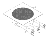
Fig. 1 is the stereogram of this novel kitchen range;
Fig. 2 is the sectional structure chart of Fig. 1 along the ZX direction;
Fig. 3 is the sectional structure chart of Fig. 1 along the XY direction;
Fig. 4 is the vertical view (inlet manifold shown in the figure) after Fig. 1 removes panel and radiation net;
Fig. 5 is the stereogram of flaring pipe shown in Figure 1 and cover cap thereof;
Fig. 6 is the stereogram of this novel kitchen range frame.
The specific embodiment
Fig. 1 Fig. 2 Fig. 3 Fig. 4 illustrates, basis is novel to be made up of kitchen range frame 11 and kitchen range, the kitchen range structure is: the indent formula infrared combustion plate 27 that is positioned at the same center of circle, open-topped three cylindrical shells and cross section and is isosceles trapezoid surrounds to forming three combustion chambers, be respectively arranged with first, second, third flaring pipe 21,22,23 that is communicated with it on three combustion chambers from outside to inside, be respectively arranged with gas nozzle 24,25,26 on the air inlet of these three flaring pipes 21,22,23, radiation net 28 is arranged on infrared combustion plate 27 tops.First, second, third flaring pipe 21,22,23 all is provided with along its corresponding combustion chamber tangential direction, and first flaring pipe 21 is opposite with the airflow direction of second flaring pipe 22, and second flaring pipe 22 is opposite with the airflow direction of the 3rd flaring pipe 23.Be evenly equipped with air admission hole 30 on first, second, third flaring pipe.
Referring to Fig. 5, first, second, third flaring pipe all disposes as the cover cap 31 of regulating intake.
Referring to Fig. 4, three gas nozzles 24,25,26 all are communicated with inlet manifold 32 through pipeline.
Referring to Fig. 6, kitchen range frame 11 structures are: have on the panel as the perforate that embeds kitchen range, the panel bottom is provided with four legs 12.Kitchen range frame front portion is provided with intake valve 13.
Referring to Fig. 2, be positioned at the equal diameters of base plate of back taper (circular cone) the platform shape of the diameter of central combustion chamber of internal layer and infrared ray burner plate (being ceramic infrared ray burner plate).The infrared combustion plate is by bonding the forming of a plurality of equicrural ladder plate assembly units (Fig. 4).Radiation net 28 helps uniform heat distribution.Three combustion chambers of kitchen range, three flaring pipes and rectangular panel 29 (Fig. 1 Fig. 2) are made by steel plate, and its surface coverage has one deck enamel layer.The same flare of inner air outlet of three flaring pipes.This novel employing ignition igniting.
Claims (6)
1. commercial infrared line energy-saving kitchen range, form by kitchen range frame (11) and kitchen range, it is characterized in that: described kitchen range structure is: be positioned at the same center of circle, open-topped three cylindrical shells and cross section are that the indent formula infrared combustion plate (27) of isosceles trapezoid surrounds to forming three combustion chambers, be respectively arranged with on three combustion chambers from outside to inside be communicated with it first, second, the 3rd flaring pipe (21,22,23), these three flaring pipes (21,22,23) be respectively arranged with gas nozzle (24 on the air inlet, 25,26), radiation net (28) is arranged on infrared combustion plate (27) top.
2. according to the line of commercial infrared shown in the claim 1 energy-saving kitchen range, it is characterized in that: described first, second, third flaring pipe (21,22,23) all is provided with along its corresponding combustion chamber tangential direction, and first flaring pipe (21) is opposite with the airflow direction of second flaring pipe (22), and second flaring pipe (22) is opposite with the airflow direction of the 3rd flaring pipe (23).
3. according to the line of commercial infrared shown in the claim 2 energy-saving kitchen range, it is characterized in that: described first, second, third flaring pipe is evenly equipped with air admission hole (30) on (21,22,23).
4. according to the line of commercial infrared shown in the claim 3 energy-saving kitchen range, it is characterized in that: described first, second, third flaring pipe (21,22,23) all disposes as the cover cap (31) of regulating intake.
5. according to the line of commercial infrared shown in the claim 4 energy-saving kitchen range, it is characterized in that: described three gas nozzles (24,25,26) all are communicated with inlet manifold (32) through pipeline.
6. according to the line of commercial infrared shown in the claim 5 energy-saving kitchen range, it is characterized in that: described kitchen range frame (11) structure is: have on the panel as the perforate that embeds kitchen range, the panel bottom is provided with four legs (12).
Priority Applications (1)
| Application Number | Priority Date | Filing Date | Title |
|---|---|---|---|
| CN2009201764318U CN201488039U (en) | 2009-08-28 | 2009-08-28 | Commercial infrared efficient energy-saving stove |
Applications Claiming Priority (1)
| Application Number | Priority Date | Filing Date | Title |
|---|---|---|---|
| CN2009201764318U CN201488039U (en) | 2009-08-28 | 2009-08-28 | Commercial infrared efficient energy-saving stove |
Publications (1)
| Publication Number | Publication Date |
|---|---|
| CN201488039U true CN201488039U (en) | 2010-05-26 |
Family
ID=42426918
Family Applications (1)
| Application Number | Title | Priority Date | Filing Date |
|---|---|---|---|
| CN2009201764318U Expired - Fee Related CN201488039U (en) | 2009-08-28 | 2009-08-28 | Commercial infrared efficient energy-saving stove |
Country Status (1)
| Country | Link |
|---|---|
| CN (1) | CN201488039U (en) |
Cited By (1)
| Publication number | Priority date | Publication date | Assignee | Title |
|---|---|---|---|---|
| CN103075800A (en) * | 2013-01-15 | 2013-05-01 | 刘迅 | Water boiler |
-
2009
- 2009-08-28 CN CN2009201764318U patent/CN201488039U/en not_active Expired - Fee Related
Cited By (1)
| Publication number | Priority date | Publication date | Assignee | Title |
|---|---|---|---|---|
| CN103075800A (en) * | 2013-01-15 | 2013-05-01 | 刘迅 | Water boiler |
Similar Documents
| Publication | Publication Date | Title |
|---|---|---|
| CN201487960U (en) | Energy-saving gas burner | |
| CN102829495A (en) | Energy-saving stove preheating premixed combustible gas by using after heat | |
| CN201964414U (en) | Burner for gas cooker | |
| CN203797719U (en) | Energy-saving and environment-friendly gas cooker | |
| CN201925923U (en) | Upper air inlet type stove burner | |
| CN201062790Y (en) | Blast type gas burner | |
| CN106765093B (en) | A kind of burner | |
| CN201488039U (en) | Commercial infrared efficient energy-saving stove | |
| CN202328399U (en) | Safe energy-saving gas stove | |
| CN201014439Y (en) | Environmental protection energy-saving gas burner | |
| CN201488038U (en) | Commercial energy-saving cooking range | |
| CN201476011U (en) | Commercial high-efficiency energy-saving cooking range | |
| CN201488037U (en) | Commercial energy-saving stove | |
| CN201265863Y (en) | Four-stage premixed turbine infrared energy-saving environment-friendly cooking stove | |
| CN201093561Y (en) | Energy saving large furnace | |
| CN202769728U (en) | Device for preheating premixed gas by utilizing waste heat | |
| CN202494141U (en) | High-efficient energy-saving infrared ray kitchen range combustor | |
| CN202598520U (en) | Double-section high fire energy-saving and environment-friendly burner | |
| CN111810992A (en) | Combustor with low vortex burning characteristic | |
| CN201421090Y (en) | Fuel gas combustor | |
| CN2644918Y (en) | Through type double ring form fire gas-fired boiler | |
| CN206094178U (en) | Single -end fries kitchen | |
| CN209588050U (en) | A kind of sufficient kitchen range of burning | |
| CN201513890U (en) | Ejection combustor | |
| CN204678407U (en) | A kind of high-power energy saving kitchen range |
Legal Events
| Date | Code | Title | Description |
|---|---|---|---|
| C14 | Grant of patent or utility model | ||
| GR01 | Patent grant | ||
| C17 | Cessation of patent right | ||
| CF01 | Termination of patent right due to non-payment of annual fee |
Granted publication date: 20100526 Termination date: 20130828 |