CN201439404U - Seal pot cover - Google Patents
Seal pot cover Download PDFInfo
- Publication number
- CN201439404U CN201439404U CN200920150345XU CN200920150345U CN201439404U CN 201439404 U CN201439404 U CN 201439404U CN 200920150345X U CN200920150345X U CN 200920150345XU CN 200920150345 U CN200920150345 U CN 200920150345U CN 201439404 U CN201439404 U CN 201439404U
- Authority
- CN
- China
- Prior art keywords
- cover body
- outer cover
- ring portion
- cover
- lid
- Prior art date
- Legal status (The legal status is an assumption and is not a legal conclusion. Google has not performed a legal analysis and makes no representation as to the accuracy of the status listed.)
- Expired - Lifetime
Links
Images


Landscapes
- Closures For Containers (AREA)
Abstract
The utility model relates to a seal pot cover, which comprises an outer cover body, an inner cover body arranged below the outer cover body, an airtight gasket sleeved in the inner cover body, a linking shaft which passes through and is inserted in the outer cover body and fixedly connected with the inner cover body, and a deflector rod which is pivoted on the linking shaft and supported against the top surface of the outer cover body; the deflector rod can be flipped to change between an unsealing position on which the linking shaft drives the inner cover body to move downward and limit relative to the outer cover body and a sealing position on which the linking shaft drives the inner cover body to move up and down relative to the outer cover body to force an airtight gasket to be supported against the pot body by airtightness. The inner cover body is linked by the deflector rod through the linking shaft to displace up and down relative to the outer cover body, thus the airtight gasket can be elastically extruded and pushed to be deformed and an airtight plug is supported against the inner circumferential surface of the pot body, and the structural design of a seal pot opening ensures that the use of the sealing function of the seal pot cover is quite convenient and simple.
Description
Technical field
The utility model relates to a kind of cover, particularly relates to a kind of sealed tank cap in order to the sealed shell of tank opening.
Background technology
The Seal Design of general common on the market sealable tank is a lot, the most general mode is after a cover cap that is provided with Airtight gasket is encapsulated in the tank body opening part, see through the mode of one or more buckle assemblies difference snap fit on tank body that will be arranged on the lid again, order about this Airtight gasket airtight stopper and be butted between lid and tank body, and reach the purpose of sealed shell of tank.But when the sealed tank cap with single buckle assembly uses; regular meeting is because the design of the brute force bullet card structure of buckle assembly; cause the suitable effort of pulling of buckle assembly; and has the sealed tank cap of a plurality of buckle assemblies; because during each dismounting; all need to pull a plurality of buckle assemblies, so inconvenient on using.
The utility model content
The purpose of this utility model is that a kind of convenient sealed tank cap that uses is being provided.
The utility model sealed tank cap, be applicable to tank body opening of cap seal, and comprise an outer cover, lid, a couple axle that is plugged on the outer cover and is fixed in lid, a driving lever that is hubbed on the couple axle that is positioned at the outer cover below, and Airtight gasket that is placed on the interior lid.This outer cover have an opening down and be covered on the described tank body and the cover body part, of sealing this tank body opening from cover body part down the upper limit ring portion, of projection from the cover body part bottom surface internal ring portion of projection down, and a plurality of spacing hook parts that are arranged at intervals on this internal ring portion.Should in lid have a base plate that is positioned at cover body part below, one up projection and outer peripheral face be concaved with the following contraposition ring portion of a ring-type embedding slot from the base plate end face, and one from up projection and be located at interval at down the lower limit ring portion of contraposition ring portion radially inner side of base plate, this lower limit ring portion has a plurality of ground that extend up and down and runs through its inside and outside side faces, but and supplies the spacing guide hole of spacing hook part upper and lower displacement ground inlay card respectively.This couple axle is can upper and lower displacement to run through to be plugged on the cover body part spacingly, and be fixed in to the relative outer cover upper and lower displacement of lid this base plate in can interlock.This driving lever is to be hubbed on the couple axle with can driving this couple axle upper and lower displacement, and has a pivot balance staff heart, and can abut against bottom face and two opposite sides in the cover body part end face respectively, and the distance of this bottom face and its pivot balance staff heart is less than the distance of any side and its pivot balance staff heart.This Airtight gasket is nested being positioned in this embedding slot, and has one and radially tiltedly go up outward and extend, and the upper limit ring portion pushing tow that can be moved down relatively and elasticity extends out and airtight outer end of compeling to be butted on the tank body inner peripheral surface.
The beneficial effects of the utility model are: seeing through this driving lever can the relative outer cover upper and lower displacement of lid in the interlock via couple axle, make Airtight gasket to be squeezed and push away distortion and airtight stopper is butted on the tank body inner peripheral surface by elasticity, and the structure design of sealed shell of tank opening, make sealed tank cap sealing function manipulate quite convenient and simple.
Description of drawings
Fig. 1 is the block diagram of the embodiment of the utility model sealed tank cap;
Fig. 2 is the three-dimensional exploded view of this embodiment;
Fig. 3 is the three-dimensional exploded view at another visual angle of this embodiment;
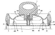
Fig. 4 is the side cutaway view of this embodiment, illustrates that outer cover is covered on the tank body, and the situation of driving lever when being positioned at sealing station;
Fig. 5 is the view of similar Fig. 4, and the situation when driving lever is positioned at the position, Kaifeng is described.
The specific embodiment
Below in conjunction with drawings and Examples the utility model is elaborated:
Shown in Fig. 1~3, the embodiment of the utility model sealed tank cap is applicable to an airtight cover front cover tank body 100 openings.The Airtight gasket 5, one that the sealing cover comprises lid 4 outer peripheral faces in interior lid 4 that an outer cover 3, one be arranged at outer cover 3 belows, airtight being nested in run through be inserted on the outer cover 3 and be consolidated in the couple axle 6 of lid 4, and driving lever 7 that pivotally is hubbed at couple axle 6 and 3 of outer cover and is positioned at outer cover 3 tops.
This outer cover 3 has a downward opening cover body part 31, one the down projection and be located at interval at the ring-type internal ring portion 35 of upper limit ring portion 33 radially inner sides from cover body part 31 bottom surfaces from articulated section 34, that cover body part 31 down is based in cover body part 31 end faces before and after the ring-type upper limit ring portion 33, two of projection at interval opposite to each other, and four be arranged on this internal ring portion 35 with being symmetrically distributed and the bottom section be stretch out internal ring portion 35 outer peripheral faces collude the spacing hook part 36 of shape.And this cover body part 31 has a rectangle perforation 310 that runs through Qi Ding, bottom surface and be positioned at 34 of articulated sections, and articulated section 34 side side in opposite directions is not equipped with a rail hole 340 of extending up and down.
Should have a base plate 41 by interior lid 4, a lower limit ring portion 42 that is based in base plate 41 end faces, a following contraposition ring portion 43 that is based in base plate 41 end faces and is located at interval at lower limit ring portion 42 radial outsides, and ring-type connecting part 44 that is based in base plate 41 end face centres, this lower limit ring portion 42 is spacing abutting against in this internal ring portion 35 outer peripheral faces, but and be equipped with four and extend and supply respectively the spacing guide hole 420 of spacing hook part 36 upper and lower displacements ground inlay card up and down, and this time contraposition ring portion 43 outer peripheral faces are concaved with a ring-type embedding slot 430, run through in it and this connecting part 44 has two, the connect apertures 440 of outer peripheral face.
These Airtight gasket 5 sections are to be the L font, and in the nested embedding slot 430 that is arranged at this time contraposition ring portion 43 in one end, and radially extending outside the embedding slot 430 on tiltedly outward one outer end 51, and the upper limit ring portion 33 of the outer cover 3 that can be moved down by lid 4 in relatively down pushes and resilient radial extends out distortion.
This couple axle 6 has in the perforation 310 that is arranged in outer cover 3 and down is inserted in axis body portion 61 in this connecting part 44, and two intervals are fixed in these axis body portion 61 lower semisections and collude card respectively and are limited in and collude shape hook part 62 in the connect apertures 440, this couple axle 6 is to be arranged in 340 in rail hole and to run through the pivot 900 of axis body portion 61 via one, but and upper and lower displacement is arranged at 34 of articulated sections spacingly.
This driving lever 7 is to be hubbed on this pivot 900 relatively outer cover 3 left and right sides pivot pendulum, and but this couple axle 6 of interlock is along 340 upper and lower displacements of rail hole, and the pivot balance staff heart 70 the distances of this driving lever 7 to its bottom face 71, less than these pivot balance staff heart 70 distances to its left and right any side 72, and can uprightly abut against in the position, Kaifeng of outer cover 3 end faces with its bottom face 71 at one, and one changes with its side 72 pivot pendulum of lying between the sealing station that is against outer cover 3 end faces.When this driving lever 7 is positioned at this position, Kaifeng, should interior lid 4 be that relative outer cover 3 moves down spacing, when this driving lever 7 is pulled pivot and is flapped toward the sealing position, this pivot 900 can drive couple axle 6 along moving on the rail hole 340, and move spacingly in driving on the lid 4 relative outer cover 3, and make Airtight gasket 5 by upper limit ring portion 33 crowded the pushing away of outer cover 3 and elasticity extends out distortion.
Shown in 3~5 figure, when will be with sealing cover airtight cover sealed cans body 100, earlier with the Kaifeng position of 7 groups of pendulum of this driving lever to vertical outer cover 3, then, this outer cover 3 is covered tank body 100 openings toward lower cover to being limited in tank body 100 tops, at this moment, spacing the abutting against of these upper limit ring portion 33 meetings in tank body 100 inner peripheral surfaces, and this lower cover 4 can be arranged in tank body 100.
Then, order about driving lever 7 pivots pendulum is against outer cover 3 end faces to lying sealing station, at this moment, since driving lever 7 sides 72 to the distance of the pivot balance staff heart 70 greater than the distance of its bottom face 71 to the pivot balance staff heart 70, so this driving lever 7 can move on the interior lid 4 relative outer cover 3 of these couple axle 6 drives of interlock, the internal ring portion 35 of this outer cover 3 can move down along lower limit ring portion 42 inner peripheral surfaces of interior lid 4, interlocked limited hook part 36 moves down along guide hole 420 simultaneously, and this upper limit ring portion 33 that these Airtight gasket 5 outer ends 51 are moved down is relatively down squeezed push away, and resilient radial extends out distortion and airtight tank body 100 inner peripheral surfaces that are closely against, and then reaches the purpose of sealed shell of tank 100 openings.At this moment, sealed tank cap is that airtight stopper is butted on the tank body 100, and is difficult for directly up separating tank body 100.
When wanting the opening encapsulation cover, except need are up pulled driving lever 7 directly, also need press down this driving lever 7, forcing couple axle 6 to drive interior lid 4 moves down, make Airtight gasket 5 break away from pushing of upper limit ring portions 33 and after the elasticity complex, sealed tank cap just is positioned at the position, Kaifeng, and can directly sealed tank cap up be separated tank body 100.
In the present embodiment, the upper limit ring portion 33 of outer cover 3 and the structure design of the following contraposition ring portion 43 of interior lid 4, and the internal ring portion 35 of outer cover 3 is understood the design that move down along lower limit ring portion 42 inner peripheral surfaces of interior lid 4, stability in can improving during relative outer cover 3 upper and lower displacements of lid 4, but when implementing, outward, interior lid 3,4 is not necessity so that upper limit ring portion 33 to be set with following contraposition ring portion 43, and this internal ring portion 35 can be designed to abut against in these lower limit ring portion 42 outer peripheral faces, and outer cover 3 so that being set, internal ring portion 35 is not necessity with lower limit ring portion 42 with interior lid 4.
Take a broad view of above-mentioned, seeing through this driving lever 7 can lid 4 relative outer cover 3 upper and lower displacement in the interlock via couple axle 6, make this Airtight gasket 5 to be squeezed and push away distortion and airtight stopper is butted on tank body 100 inner peripheral surfaces by elasticity, and the structure design of sealed shell of tank 100 openings, can see through and simply pull the sealing function that this driving lever 7 is controlled sealed tank cap, quite convenient and simple in the use, can reach the purpose of this utility model really.
Claims (2)
1. sealed tank cap, be applicable to tank body opening of cap seal, the sealing cover comprises an outer cover, an interior lid that is arranged at the outer cover below, one runs through the couple axle that is plugged on the outer cover and is fixed in interior lid, a driving lever that is hubbed on the couple axle, and Airtight gasket that is placed on the interior lid, this outer cover has an opening and be covered on the described tank body and the cover body part of sealing this tank body opening down, and one from the cover body part upper limit ring portion of projection down, should have a base plate that is positioned at the cover body part below by interior lid, and one from the base plate end face up projection and outer peripheral face are concaved with the following contraposition ring portion of a ring-type embedding slot, this couple axle is can upper and lower displacement to run through to be plugged on the cover body part spacingly, and can be fixed in to the interior relative outer cover upper and lower displacement of lid of interlock this base plate, this driving lever is to be hubbed between couple axle and outer cover with can driving this couple axle upper and lower displacement, and has a pivot balance staff heart, and can abut against bottom face and two opposite sides respectively in the cover body part end face, and the distance of this bottom face and its pivot balance staff heart is less than the distance of any side and its pivot balance staff heart, this Airtight gasket is nested being positioned in this embedding slot, and have one and radially tiltedly go up outward and extend, and the upper limit ring portion pushing tow that can be moved down relatively and elasticity extend out and airtight outer end of compeling to be butted on the tank body inner peripheral surface, it is characterized in that, this outer cover also have one from the cover body part bottom surface the down internal ring portion of projection and a plurality of spacing hook part that is arranged at intervals on this internal ring portion, should in lid also have one from up projection and be located at interval at down the lower limit ring portion of contraposition ring portion radially inner side of base plate, and this lower limit ring portion has a plurality of extensions up and down ground and runs through in it, outer peripheral face, but and supply the spacing guide hole of spacing hook part upper and lower displacement ground inlay card respectively.
2. sealed tank cap as claimed in claim 1, it is characterized in that, should in lid also have one from the base plate centre ring-type connecting part of projection up, and this connecting part is equipped with two connect apertures that run through its inside and outside side face, this couple axle has one can run through to upper and lower displacement the axis body portion that is plugged on the cover body part and articulates with driving lever, and two intervals be fixed in axis body portion lower semisection collude the shape hook part, this axis body portion down is inserted in the connecting part, and hook part is to collude card respectively to be limited in the connect apertures.
Priority Applications (1)
| Application Number | Priority Date | Filing Date | Title |
|---|---|---|---|
| CN200920150345XU CN201439404U (en) | 2009-05-11 | 2009-05-11 | Seal pot cover |
Applications Claiming Priority (1)
| Application Number | Priority Date | Filing Date | Title |
|---|---|---|---|
| CN200920150345XU CN201439404U (en) | 2009-05-11 | 2009-05-11 | Seal pot cover |
Publications (1)
| Publication Number | Publication Date |
|---|---|
| CN201439404U true CN201439404U (en) | 2010-04-21 |
Family
ID=42544071
Family Applications (1)
| Application Number | Title | Priority Date | Filing Date |
|---|---|---|---|
| CN200920150345XU Expired - Lifetime CN201439404U (en) | 2009-05-11 | 2009-05-11 | Seal pot cover |
Country Status (1)
| Country | Link |
|---|---|
| CN (1) | CN201439404U (en) |
Cited By (6)
| Publication number | Priority date | Publication date | Assignee | Title |
|---|---|---|---|---|
| CN102963607A (en) * | 2012-11-13 | 2013-03-13 | 宁波利时日用品有限公司 | Closed box |
| GB2495721A (en) * | 2011-10-18 | 2013-04-24 | Alastair Mcdonald Hyland | Container with adjustable airtight lid |
| CN105691551A (en) * | 2016-01-26 | 2016-06-22 | 张立 | Cover plate for top opening of cabin |
| CN111591582A (en) * | 2019-02-20 | 2020-08-28 | 飞绿股份有限公司 | Cover body closing structure of sealed tank |
| CN115196183A (en) * | 2021-04-13 | 2022-10-18 | 飞绿股份有限公司 | Sealing cover with bidirectional buckle mechanism |
| US11745921B2 (en) | 2019-02-06 | 2023-09-05 | Free-Free Industrial Corp | Sealing cover with two-way embedding buckle mechanism |
-
2009
- 2009-05-11 CN CN200920150345XU patent/CN201439404U/en not_active Expired - Lifetime
Cited By (6)
| Publication number | Priority date | Publication date | Assignee | Title |
|---|---|---|---|---|
| GB2495721A (en) * | 2011-10-18 | 2013-04-24 | Alastair Mcdonald Hyland | Container with adjustable airtight lid |
| CN102963607A (en) * | 2012-11-13 | 2013-03-13 | 宁波利时日用品有限公司 | Closed box |
| CN105691551A (en) * | 2016-01-26 | 2016-06-22 | 张立 | Cover plate for top opening of cabin |
| US11745921B2 (en) | 2019-02-06 | 2023-09-05 | Free-Free Industrial Corp | Sealing cover with two-way embedding buckle mechanism |
| CN111591582A (en) * | 2019-02-20 | 2020-08-28 | 飞绿股份有限公司 | Cover body closing structure of sealed tank |
| CN115196183A (en) * | 2021-04-13 | 2022-10-18 | 飞绿股份有限公司 | Sealing cover with bidirectional buckle mechanism |
Similar Documents
| Publication | Publication Date | Title |
|---|---|---|
| CN201439404U (en) | Seal pot cover | |
| CN201296433Y (en) | Sealed pot cover | |
| CN202022414U (en) | Reversible push-pull food box cover | |
| CN202968053U (en) | Shaping device for sealed aluminium film cover | |
| CN202132403U (en) | Riveting structure for shaft sleeve and thin-plate shaped bracket | |
| CN202318668U (en) | Side core-pulling mechanism | |
| CN206333766U (en) | The pot cover and electric cooker of electric cooker | |
| CN2734654Y (en) | Combined cover for medical liquid bottle | |
| CN201068257Y (en) | Aluminum and plastic combined anti-theft bottle cap | |
| CN107595061A (en) | A kind of liftable cup of inner bag | |
| CN209417982U (en) | Simple hand-operated formula chinese disply box | |
| CN2892067Y (en) | Composite cap for major cycle transfusion plastical soft package | |
| CN202464388U (en) | Sealing easy-to-buckle lid | |
| CN209553756U (en) | A kind of folding carton | |
| CN206537577U (en) | A kind of novel pressure punch-out equipment | |
| CN203846531U (en) | Push-pull type easily-opened well lid | |
| CN205418739U (en) | Garbage can | |
| CN209573565U (en) | A kind of Novel draw-bar box | |
| CN203314639U (en) | Dismountable cup | |
| CN210351148U (en) | DMR standard interphone | |
| CN209718535U (en) | A kind of injection mold ejecting mechanism | |
| CN202337399U (en) | Novel packaging bottle | |
| CN211996250U (en) | Capping machine head for filling paste | |
| CN208906552U (en) | A kind of mould structure of the line position with ejector sleeve | |
| CN202400399U (en) | Snake oil nourishing honey bottle |
Legal Events
| Date | Code | Title | Description |
|---|---|---|---|
| C14 | Grant of patent or utility model | ||
| GR01 | Patent grant | ||
| CX01 | Expiry of patent term |
Granted publication date: 20100421 |
|
| CX01 | Expiry of patent term |