CN201369521Y - Bottom-upward pulley - Google Patents

Bottom-upward pulley Download PDF

Info

Publication number
CN201369521Y
CN201369521Y CNU2009201263028U CN200920126302U CN201369521Y CN 201369521 Y CN201369521 Y CN 201369521Y CN U2009201263028 U CNU2009201263028 U CN U2009201263028U CN 200920126302 U CN200920126302 U CN 200920126302U CN 201369521 Y CN201369521 Y CN 201369521Y
Authority
CN
China
Prior art keywords
connecting pin
support
base
towards
pin
Prior art date
Legal status (The legal status is an assumption and is not a legal conclusion. Google has not performed a legal analysis and makes no representation as to the accuracy of the status listed.)
Expired - Fee Related
Application number
CNU2009201263028U
Other languages
Chinese (zh)
Inventor
陈其
徐韬
戴晓峰
兰春耀
陈晓勇
党勇
谭富强
张宁
Current Assignee (The listed assignees may be inaccurate. Google has not performed a legal analysis and makes no representation or warranty as to the accuracy of the list.)
State Grid Corp of China SGCC
Chongqing City Power Supply Co of State Grid Chongqing Electric Power Co Ltd
Original Assignee
Shapingba Power Supply Bureau Of Chongqing Electric Power Co
Priority date (The priority date is an assumption and is not a legal conclusion. Google has not performed a legal analysis and makes no representation as to the accuracy of the date listed.)
Filing date
Publication date
Application filed by Shapingba Power Supply Bureau Of Chongqing Electric Power Co filed Critical Shapingba Power Supply Bureau Of Chongqing Electric Power Co
Priority to CNU2009201263028U priority Critical patent/CN201369521Y/en
Application granted granted Critical
Publication of CN201369521Y publication Critical patent/CN201369521Y/en
Anticipated expiration legal-status Critical
Expired - Fee Related legal-status Critical Current

Links

Images

Landscapes

  • Table Equipment (AREA)
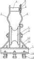
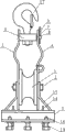
Abstract

The utility model relates to a bottom-upward pulley, comprising a roller wheel, a pin shaft and two brackets; the roller wheel is movably arranged on the pin shaft, and the pin shaft is arranged between the two brackets; the bottom-upward pulley comprises a base, the cross section of the base is a U shape, the bottom part of the base is provided with a bolt, the lower ends of the two brackets are respectively arranged on the base, wherein the upper end of one bracket is fixedly provided with a connecting pin, and the other bracket is provided with an upper part and a lower part which are articulated with each other, and the upper part is connected with the connecting pin in a close-open way. By adopting the technical proposal, the bottom-upward pulley has the advantages of convenient installation, high intensity and convenient usage, can reduce the labor intensity of operators, avoids from sliding of lead wires and improves the safety factor.

Description

Towards the sky coaster
Technical field
The utility model relates to a kind of power equipment, and is particularly a kind of towards the sky coaster.
Background technology
When electric power is carried, general all is lead to be installed on the porcelain vase of electric pole transport, because porcelain vase is in the high-altitude, nature breakage and outside destroy take place in porcelain vase easily that place lead, just need to change porcelain vase, and lead is arranged on the porcelain vase, when changing porcelain vase, need lead is removed from porcelain vase, at present, the operator normally stands on the electric pole, with one hand or shoulder lead is moved on the coaster, this coaster comprises roller, bearing pin and hook, this coaster is to be suspended on the cross-arm screw rod by hook, and the position of coaster is lower, makes when operation, the operator just must lean to one side supporting lead with one hand or shoulder, after lead walked around cross-arm, be placed on the roller upper support of coaster again, owing to be work high above the ground, the all impossible complete equipilibrium of people's center of gravity power, the lead pressure that in addition bears on the porcelain vase is all very big, adopts above-mentioned coaster to have the following disadvantages in use: the one, and dangerous, accidents caused easily; The 2nd, lead need be walked around cross-arm, lean to one side time of support wire of operator is longer, makes labour intensity big; The 3rd, maintenance time is long, has prolonged interruption duration, has reduced power supply reliability; The 4th, when mobile lead,, also need tie up on lead with rope by behind rope on the bolt of electric pole top in order to prevent the lead landing, make inconvenient operation like this.
Summary of the invention
The purpose of this utility model just provides a kind of intensity height, easy to use towards the sky coaster, and it can reduce operator's labour intensity, improves coefficient is installed.
The purpose of this utility model is to realize by such technical scheme, comprise roller, bearing pin and two supports, roller is installed on the bearing pin versatilely, bearing pin is installed between two supports, it is characterized in that: it also comprises base, the base cross section takes the shape of the letter U, bottom at base is provided with bolt, two support lower ends are installed on the base respectively, the intrinsic connecting pin in the upper end of a support wherein, another support has upper and lower two partly, and upper part is connected but upper part is folding with connecting pin with partly hinged each other down.
When changing porcelain vase, the utility model is hung on electric pole, by the open card of base on the angle steel cross-arm of straight line pole, again by bolt, make installation very convenient, open the upper part support and form the inlet wire breach, the operator may stand on the cross-arm, and both hands are carried lead, again lead is positioned over the roller upper support by breach, the upper part support is fixed on the connecting pin, treat porcelain vase change finish after, open the upper part support lead moved on the porcelain vase.Because after having adopted the utility model, operator's both hands are firmly being carried lead, make more convenient operation, compare with adopting existing coaster, in use, it is more laborsaving that both hands are upwards firmly being put forward the lead ratio one hand downward support wire of exerting oneself of leaning to one side, and need not lead is walked around cross-arm, obviously shortened the supporting time of operator to lead, reduce operator's labour intensity, need not to lean to one side to operate, improve coefficient of safety, also avoided the landing of lead.
Owing to adopted technique scheme, the utlity model has easy for installation, intensity height, advantage easy to use, it can reduce operator's labour intensity, has avoided the landing of lead, has improved coefficient of safety.
Description of drawings
Description of drawings of the present utility model is as follows:
Fig. 1 is the structural representation of first kind of embodiment of the utility model;
Fig. 2 is the structural representation of second kind of embodiment of the utility model;
Fig. 3 is the right view of Fig. 2;
The schematic diagram that Fig. 4 opens for Fig. 2 medium-height trestle;
Fig. 5 is the structural representation of the third embodiment of the utility model;
Fig. 6 is the right view of Fig. 5;
Fig. 7 is the structural representation of the 4th kind of embodiment of the utility model;
Fig. 8 is the user mode reference diagram of Fig. 2.
Among the figure: 1. roller; 2. bearing pin; 3. support; 4. support; 5. base; 6. connecting pin; 7. via hole; 8. hole; 9. alignment pin; 10. spacing edge-cut; 11. via hole; 12. positive stop lug boss; 13. circular metal plate; 14. reinforcement; 15. stiffener; 16. frustum; 17. hook; 18. wire; 19. bolt; 20. angle steel cross-arm.
Embodiment
The utility model is described in further detail below in conjunction with drawings and Examples:
Shown in Fig. 1,2,4,5,7, the utility model comprises roller 1, bearing pin 2 and two supports 3,4, roller 1 is installed on the bearing pin 2 versatilely, bearing pin 2 is installed between two supports 3,4, it is characterized in that: it also comprises base 5, base 5 cross sections take the shape of the letter U, be provided with bolt 19 in the bottom of base 5, two support 3,4 lower ends are installed in respectively on the base 5, the intrinsic connecting pin 6 in the upper end of a support 3 wherein, another support 4 has upper and lower two partly, and upper part is connected but upper part is folding with connecting pin 6 with partly hinged each other down.
As shown in Figure 8, when changing porcelain vase, the utility model is hung on electric pole, by the open card of base 5 on the angle steel cross-arm 20 of straight line pole, by bolt, make installation very convenient again, open the upper part support and form the inlet wire breach, the operator may stand on the cross-arm, both hands are carried lead, again lead are positioned over roller 1 upper support by breach, and the upper part support is fixed on the connecting pin 6, after treating that the porcelain vase replacing finishes, open the upper part support lead is moved on the porcelain vase.Because after having adopted the utility model, operator's both hands are firmly being carried lead, make more convenient operation, compare with adopting existing coaster, in use, it is more laborsaving that both hands are upwards firmly being put forward the lead ratio one hand downward support wire of exerting oneself of leaning to one side, and need not lead is walked around cross-arm, obviously shortened the supporting time of operator to lead, reduce operator's labour intensity, need not to lean to one side to operate, improve coefficient of safety, also avoided the landing of lead.
As shown in Figure 1, 2, 3, but support 4 is folding like this with connecting pin 6 and is connected: be provided with via hole 7 in the upper end of support upper part, via hole 7 is passed in connecting pin 6 terminations, and be provided with in the termination of connecting pin 6 porose 8, by carrying out spacing to support 4 upper parts in alignment pin 9 patchholes 8.As shown in Figure 4, when opening support, extract connecting pin 6, make the upper part support form the inlet wire breach.
Shown in Fig. 5,6, but support 4 is folding like this with connecting pin 6 and is connected: be provided with the via hole 11 of band spacing edge-cut 10 in the upper end of support upper part, the circular metal plate 13 with the via hole 11 corresponding band positive stop lug boss 12 of being with spacing edge-cut 10 is installed on connecting pin 6.When opening support, when the positive stop lug boss 12 of circular metal plate 13 is adjusted to spacing edge-cut 10 opposite positions with via hole 11, pull out the upper part support and form the inlet wire breach.
As shown in Figure 7, be connected but support 4 is folding like this with connecting pin 6: be provided with via hole 7 in the upper end of support upper part, via hole 7 is passed in connecting pin 6 terminations, and is provided with screw thread in the termination of connecting pin 6, and nut sleeve is on connecting pin 6.When opening support, only need take off nut.
Shown in Fig. 1~7, for the U-shaped opening part that prevents base deforms after long between in use, base 5 is provided with reinforcement 14.
Shown in Fig. 1,2,4,5,7, for when the support wire, prevent that two stands from deforming, between two stands 3,4 and base 5, be respectively arranged with stiffener 15.
Shown in Fig. 1,5,7, bolt 19 is three, and the front end of every bolt 19 has frustum 16.In order to prevent that screw thread is damaged.
Shown in Fig. 2~7, intrinsic hook 17 on connecting pin 6.In order to hang use, can be installed on the cross-arm again and use.
As shown in Figure 3, drop when using or carrying in order to prevent alignment pin, alignment pin 9 is fixed on the support 4 by wire 18.
In sum, but the utility model can also adopt other version that support 4 is folding with connecting pin 6 is connected.

Claims (9)

1. one kind towards the sky coaster, comprise roller (1), bearing pin (2) and two supports (3,4), roller (1) is installed on the bearing pin (2) versatilely, bearing pin (2) is installed in two supports (3,4) between, it is characterized in that: it also comprises base (5), base (5) cross section takes the shape of the letter U, be provided with bolt (19) in the bottom of base (5), two supports (3,4) lower end is installed in respectively on the base (5), the intrinsic connecting pin in upper end (6) of a support (3) wherein, on another support (4) has, down two partly, and upper part is with partly hinged each other down, upper part with connecting pin (6) but be folding and be connected.
2. as claimed in claim 1 towards the sky coaster, it is characterized in that support (4) with connecting pin (6) but be folding like this and be connected: be provided with via hole (7) in the upper end of support upper part, via hole (7) is passed in connecting pin (6) termination, and porose (8) are set in the termination of connecting pin (6), carry out spacing by in alignment pin (9) patchhole (8) to support (4) upper part.
3. as claimed in claim 1 towards the sky coaster, it is characterized in that support (4) with connecting pin (6) but be folding like this and be connected: be provided with the via hole (11) of band spacing edge-cut (10) in the upper end of support upper part, go up the circular metal plate of installing with the corresponding band positive stop lug boss of via hole (11) (12) of band spacing edge-cut (10) (13) at connecting pin (6).
4. as claimed in claim 1 towards the sky coaster, it is characterized in that support (4) with connecting pin (6) but be folding like this and be connected: be provided with via hole (7) in the upper end of support upper part, via hole (7) is passed in connecting pin (6) termination, and being provided with screw thread in the termination of connecting pin (6), nut sleeve is on connecting pin (6).
5. as claim 1,2,3 or 4 described towards the sky coaster, it is characterized in that: base (5) is provided with reinforcement (14).
6. as claimed in claim 5 towards the sky coaster, it is characterized in that: between two stands (3,4) and base (5), be respectively arranged with stiffener (15).
7. as claimed in claim 6 towards the sky coaster, it is characterized in that: described bolt (19) is three, and the front end of every bolt (19) has frustum (16).
8. as claimed in claim 7 towards the sky coaster, it is characterized in that: go up intrinsic hook (17) at connecting pin (6).
9. as claimed in claim 2 towards the sky coaster, it is characterized in that: described alignment pin (9) is fixed on the support (4) by wire (18).
CNU2009201263028U 2009-02-11 2009-02-11 Bottom-upward pulley Expired - Fee Related CN201369521Y (en)

Priority Applications (1)

Application Number Priority Date Filing Date Title
CNU2009201263028U CN201369521Y (en) 2009-02-11 2009-02-11 Bottom-upward pulley

Applications Claiming Priority (1)

Application Number Priority Date Filing Date Title
CNU2009201263028U CN201369521Y (en) 2009-02-11 2009-02-11 Bottom-upward pulley

Publications (1)

Publication Number Publication Date
CN201369521Y true CN201369521Y (en) 2009-12-23

Family

ID=41488413

Family Applications (1)

Application Number Title Priority Date Filing Date
CNU2009201263028U Expired - Fee Related CN201369521Y (en) 2009-02-11 2009-02-11 Bottom-upward pulley

Country Status (1)

Country Link
CN (1) CN201369521Y (en)

Cited By (7)

* Cited by examiner, † Cited by third party
Publication number Priority date Publication date Assignee Title
CN102013645A (en) * 2010-11-18 2011-04-13 重庆市电力公司江北供电局 Hauling cable positioning labor-saving guide wheel
CN102064491A (en) * 2010-10-25 2011-05-18 河北省电力公司超高压输变电分公司 High-altitude operation device applied to high-altitude operation
CN103594975A (en) * 2013-11-25 2014-02-19 国家电网公司 Tackle fixing plate for overhead line stringing
CN103594974A (en) * 2013-11-25 2014-02-19 国家电网公司 Yoke plate tightener for overhead line stringing
CN103594976A (en) * 2013-11-25 2014-02-19 国家电网公司 Combined stringing tool used for line conductor stringing
CN104882824A (en) * 2015-06-15 2015-09-02 国网四川省电力公司泸州供电公司 Lead and ground wire groove-jumping prevention device and using method thereof
CN105140862A (en) * 2015-09-03 2015-12-09 国家电网公司 Power line wind rope fastener

Cited By (12)

* Cited by examiner, † Cited by third party
Publication number Priority date Publication date Assignee Title
CN102064491A (en) * 2010-10-25 2011-05-18 河北省电力公司超高压输变电分公司 High-altitude operation device applied to high-altitude operation
CN102064491B (en) * 2010-10-25 2013-10-23 国家电网公司 High-altitude operation device applied to high-altitude operation
CN102013645A (en) * 2010-11-18 2011-04-13 重庆市电力公司江北供电局 Hauling cable positioning labor-saving guide wheel
CN102013645B (en) * 2010-11-18 2012-10-31 重庆市电力公司江北供电局 Hauling cable positioning labor-saving guide wheel
CN103594975A (en) * 2013-11-25 2014-02-19 国家电网公司 Tackle fixing plate for overhead line stringing
CN103594974A (en) * 2013-11-25 2014-02-19 国家电网公司 Yoke plate tightener for overhead line stringing
CN103594976A (en) * 2013-11-25 2014-02-19 国家电网公司 Combined stringing tool used for line conductor stringing
CN103594976B (en) * 2013-11-25 2016-06-29 国家电网公司 Combination stringing instrument for line conductor stringing
CN103594974B (en) * 2013-11-25 2017-05-03 国家电网公司 Combined tightener for overhead line stringing
CN104882824A (en) * 2015-06-15 2015-09-02 国网四川省电力公司泸州供电公司 Lead and ground wire groove-jumping prevention device and using method thereof
CN104882824B (en) * 2015-06-15 2017-03-01 国网四川省电力公司泸州供电公司 A kind of lead wire and earth wire groove-jumping-preventing device and its using method
CN105140862A (en) * 2015-09-03 2015-12-09 国家电网公司 Power line wind rope fastener

Similar Documents

Publication Publication Date Title
CN201369521Y (en) Bottom-upward pulley
CN201904568U (en) Overhead ground wire lifting device
CN202217968U (en) Lifting type paying-off tackle for wires in power distribution lines
CN108551009B (en) Grounding wire suspension device
CN101237128A (en) A line pole operation chair
CN208889879U (en) 220kV is grounded auxiliary tool
CN104617515A (en) 10KV distribution line pole top maintenance supporting rod
CN201157157Y (en) Operation chair for line rod
CN202340093U (en) Equipment live mounting hoist device on power supply circuit post
CN202474703U (en) Overhead ground wire lifting mechanism
CN201887378U (en) Auxiliary working rack for transmission line pole or tower maintenance
CN202917926U (en) Span line laying device
CN201321352Y (en) Special lifting device for electrical equipment
CN205087828U (en) Simple and easy lifting device of 35kV circuit breaker
CN200986977Y (en) Slideway type earthed pole
CN202333176U (en) Double-row grounding wire hanging bracket
CN204481399U (en) 10kV distribution line masthead maintenance and support bar
CN201611741U (en) Lifting device used for power equipment
CN212224199U (en) Scaffold convenient to adjust for power equipment overhaul
CN204202135U (en) The pre-buried air conditoner support of construction wall
CN203577185U (en) Shifting mechanism in times of power transmission and distribution line repair
CN207700824U (en) A kind of body of rod draws high device
CN202417285U (en) Rotatable rigid ladder for maintenance of power transmission lines
CN201074149Y (en) Roof collapse preventing stop
CN202190023U (en) Wire bracing device for overhead wire

Legal Events

Date Code Title Description
C14 Grant of patent or utility model
GR01 Patent grant
ASS Succession or assignment of patent right

Owner name: STATE GRID CORPORATION OF CHINA

Free format text: FORMER OWNER: CHONGQING ELECTRIC POWER CORP SHAPINGBA POWER SUPPLY BUREAU

Effective date: 20140313

Owner name: STATE GRID CHONGQING ELECTRIC POWER COMPANY URBAN

Effective date: 20140313

C41 Transfer of patent application or patent right or utility model
COR Change of bibliographic data

Free format text: CORRECT: ADDRESS; FROM: 400030 SHAPINGBA, CHONGQING TO: 100031 XICHENG, BEIJING

TR01 Transfer of patent right

Effective date of registration: 20140313

Address after: 100031 Xicheng District West Chang'an Avenue, No. 86, Beijing

Patentee after: State Grid Corporation of China

Patentee after: Urban Power Supply Branch of State Grid Chongqing Electric Power Company

Address before: 400030 science and Technology Information Center of Shapingba Power Supply Bureau, No. 4 middle Sha Road, Shapingba District, Chongqing

Patentee before: Chongqing Electric Power Corp Shapingba Power Supply Bureau

CF01 Termination of patent right due to non-payment of annual fee

Granted publication date: 20091223

Termination date: 20180211