CN201360014Y - Opening-closing device of door lock battery box cover - Google Patents
Opening-closing device of door lock battery box cover Download PDFInfo
- Publication number
- CN201360014Y CN201360014Y CNU200820235642XU CN200820235642U CN201360014Y CN 201360014 Y CN201360014 Y CN 201360014Y CN U200820235642X U CNU200820235642X U CN U200820235642XU CN 200820235642 U CN200820235642 U CN 200820235642U CN 201360014 Y CN201360014 Y CN 201360014Y
- Authority
- CN
- China
- Prior art keywords
- button
- battery case
- case lid
- locking face
- spring
- Prior art date
- Legal status (The legal status is an assumption and is not a legal conclusion. Google has not performed a legal analysis and makes no representation as to the accuracy of the status listed.)
- Expired - Lifetime
Links
Images


Classifications
-
- Y—GENERAL TAGGING OF NEW TECHNOLOGICAL DEVELOPMENTS; GENERAL TAGGING OF CROSS-SECTIONAL TECHNOLOGIES SPANNING OVER SEVERAL SECTIONS OF THE IPC; TECHNICAL SUBJECTS COVERED BY FORMER USPC CROSS-REFERENCE ART COLLECTIONS [XRACs] AND DIGESTS
- Y02—TECHNOLOGIES OR APPLICATIONS FOR MITIGATION OR ADAPTATION AGAINST CLIMATE CHANGE
- Y02E—REDUCTION OF GREENHOUSE GAS [GHG] EMISSIONS, RELATED TO ENERGY GENERATION, TRANSMISSION OR DISTRIBUTION
- Y02E60/00—Enabling technologies; Technologies with a potential or indirect contribution to GHG emissions mitigation
- Y02E60/10—Energy storage using batteries
Abstract
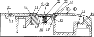
The utility model relates to an opening-closing device of a door lock battery box cover, which comprises a pushbutton (1), a spring (2), a rear locking surface (3) and a battery box cover (4). The spring (2) is arranged between the pushbutton (1) and the rear locking surface (3); the battery box cover (4) is provided with a through hole which is sleeved on the pushbutton (1), forms a limit structure with the pushbutton (1) and is buckled with clamp slots 31 and 34 on the rear locking surface (3) as a whole through clamp points 41 and 44; the pushbutton (1) is arranged in a groove of the rear locking surface (3) and pressed in the groove of the rear locking surface (3) when the spring (2) is compacted under the external force; and the battery box cover (4) can move horizontally relatively to the rear locking surface (3) to open the battery box cover. When the external force exerted on the pushbutton (1) is removed, the pushbutton (1) bounces out of the groove of the rear locking surface (3) under the rebounding force of the spring (2), and extends into the through hole of the battery box cover (4) to limit the horizontal movement of the battery box cover (4) relatively to the rear locking surface (3). With the structure, the door lock battery can be conveniently replaced, thereby improving the safety performance.
Description
Technical field
The utility model relates to a kind of parts of lock, particularly a kind of opening/closing device of door lock battery case lid.
Background technology
At present, the opening/closing device of door lock battery case lid, in existing technology, generally employing instrument on/off operation of assisting or simple sliding cover type ON/OFF not only influence attractive in appearancely, and are waiting to improve aspect convenient, security performance.
Summary of the invention
The purpose of this utility model is in order to overcome above-mentioned defective, a kind of opening/closing device of changing convenient, the safe door lock battery case lid of battery to be provided.
In order to achieve the above object, the technical solution of the utility model is as follows:
The opening/closing device of door lock battery case lid, comprise button 1., spring 2., the back locking face 3., battery case lid 4.; Button 1. and the back locking face spring is housed 2. between 3., battery case lid has a borehole jack to be contained in button on 4. 1. to go up, 1. form position limiting structure with button, and by 3. draw-in groove 31,34 spiral-locks formation one of stuck point 41,44 and back locking face.
2. spring is not limited to this spring mode with the function that 1. button is realized.
1. button is contained in the locking face groove 3. of back, and 2. 1. button tighten spring by external force and be pressed in the back locking face groove 3., and battery case lid is 3. move left and right of back locking face relatively 4., and then opens battery case lid; When button external force was 1. cancelled, button ejected from back locking face groove 3., and puts in the battery case lid through hole 4. 1. under spring bounce-back 2., and the limit battery lid is back locking face move left and right 3. relatively 4..
Owing to adopted said structure, the replacing of door lock battery is very convenient, has improved security performance, and simple in structure, is easy to produce.
Description of drawings
4. Fig. 1 battery case lid is closely buckled in the schematic diagram that 3. the back locking face is gone up
1. Fig. 2 button is pressed into 3. groove schematic diagram of back locking face
1. Fig. 3 button is pressed into 3. loading, unloading battery case lid schematic diagram behind the groove of back locking face
Embodiment
Below in conjunction with drawings and Examples the utility model is described in further detail:
The opening/closing device of door lock battery case lid, comprise button 1., spring 2., the back locking face 3., battery case lid 4.; Button 1. and the back locking face spring is housed 2. between 3., battery case lid has a borehole jack to be contained in button on 4. 1. to go up, 1. form position limiting structure with button, and by 3. draw-in groove 31,34 spiral-locks formation one of stuck point 41,44 and back locking face.
1. button is contained in the locking face groove 3. of back, and 2. 1. button tighten spring by external force and be pressed in the back locking face groove 3., and battery case lid is 3. move left and right of back locking face relatively 4., and then opens battery case lid; When button external force was 1. cancelled, button ejected from back locking face groove 3., and puts in the battery case lid through hole 4. 1. under spring bounce-back 2., and the limit battery lid is back locking face move left and right 3. relatively 4..
By shown in Figure 1: the back locking face has stuck point 31,34 on 3., and corresponding battery case lid draw-in groove 41,44 4. respectively, and 4. spiral-lock is when 3. the back locking face is gone up when battery case lid, and 31 block 41,34 blocks 44, prevents that 3. 4. battery case lid upwards break away from the back locking face; Button has on 1. rib 13 and spring upper surface 21 2. to offset, 3. back locking face has rib 35 and spring lower surface 22 2. to offset, 1. button has left and right sides silhouette edge 11,12,3. back locking face has groove limit, the left and right sides 32,33,4. battery case lid has through hole limit, the left and right sides 42,43, and wherein 1. 4. locking face 3. left groove limit 32, corresponding respectively back, left profile limit 11 and battery case lid have left through hole limit 42 to button; 4. corresponding respectively locking face 3. right groove limit 33, back of the 1. right silhouette edge 12 of button and battery case lid have right through hole limit 43;
Press Fig. 2, shown in Figure 3: under the positive pressure of external force, 1. button tightens spring and withdraws from the through hole of battery case lid through hole limit, the left and right sides 42,43 formation 4. fully, in the groove that locking face groove limit, the left and right sides 32,33 3. forms after the indentation, button this moment left and right sides silhouette edge 11,12 and battery case lid through hole limit, the left and right sides 42,43 4. 1. do not offset fully, battery case lid 4. can be fully with respect to button 1. with 3. move left and right of back locking face, i.e. 4. detachable of battery case lid.
As shown in Figure 2, when the external force effect of malleation is cancelled, button is 1. under spring bounce-back 2., from 3. left and right sides groove limit 32 of locking face, back, eject in 33 grooves that form, and put in 4. left and right sides through hole limit 42 of battery case lid, in 43 through holes that form, this moment button left profile limit 11 1. respectively with the 3. left groove of back locking face limit 32, battery case lid left through hole limit 42 4. offsets, button right silhouette edge 12 1. respectively with locking face 3. right groove limit, back 33, battery case lid right through hole limit 43 4. offsets, back locking face has stuck point 31 on 3., 34 respectively with battery case lid draw-in groove 41 4., 44 offset, and promptly 3. 1. 4. battery case lid can not move up and down with the back locking face by relative key.
Claims (3)
1, the opening/closing device of door lock battery case lid is characterized in that: comprise button (1), spring (2), back locking face (3), battery case lid (4); Between button (1) and back locking face (3), spring (2) is housed, there is a through hole to be sleeved on the button (1) on the battery case lid (4), form position limiting structure with button (1), and form one with draw-in groove (31), (34) spiral-lock of back locking face (3) by its stuck point (41), (44).
2, the opening/closing device of door lock battery case lid according to claim 1 is characterized in that the function that spring (2) and button (1) are realized can be spring or shell fragment mode.
3, the opening/closing device of door lock battery case lid according to claim 1, it is characterized in that button (1) is contained in the groove of back locking face (3), button (1) tightens spring (2) in the groove that is pressed into back locking face (3) by external force, battery case lid (4) is back locking face (3) move left and right relatively, and then opens battery case lid; When the external force of button (1) was cancelled, button (1) ejected from the groove of back locking face (3), and puts in the through hole of battery case lid (4) under the bounce-back of spring (2), and limit battery lid (4) is the move left and right of back locking face (3) relatively.
Priority Applications (1)
| Application Number | Priority Date | Filing Date | Title |
|---|---|---|---|
| CNU200820235642XU CN201360014Y (en) | 2008-12-29 | 2008-12-29 | Opening-closing device of door lock battery box cover |
Applications Claiming Priority (1)
| Application Number | Priority Date | Filing Date | Title |
|---|---|---|---|
| CNU200820235642XU CN201360014Y (en) | 2008-12-29 | 2008-12-29 | Opening-closing device of door lock battery box cover |
Publications (1)
| Publication Number | Publication Date |
|---|---|
| CN201360014Y true CN201360014Y (en) | 2009-12-09 |
Family
ID=41425780
Family Applications (1)
| Application Number | Title | Priority Date | Filing Date |
|---|---|---|---|
| CNU200820235642XU Expired - Lifetime CN201360014Y (en) | 2008-12-29 | 2008-12-29 | Opening-closing device of door lock battery box cover |
Country Status (1)
| Country | Link |
|---|---|
| CN (1) | CN201360014Y (en) |
Cited By (2)
| Publication number | Priority date | Publication date | Assignee | Title |
|---|---|---|---|---|
| CN109110224A (en) * | 2018-10-28 | 2019-01-01 | 广东顺德可可麦科技产业孵化有限公司 | Hand-held sealer |
| CN110854326A (en) * | 2019-11-19 | 2020-02-28 | 陈新宇 | Dry battery installation device for bounce type remote controller |
-
2008
- 2008-12-29 CN CNU200820235642XU patent/CN201360014Y/en not_active Expired - Lifetime
Cited By (4)
| Publication number | Priority date | Publication date | Assignee | Title |
|---|---|---|---|---|
| CN109110224A (en) * | 2018-10-28 | 2019-01-01 | 广东顺德可可麦科技产业孵化有限公司 | Hand-held sealer |
| CN109110224B (en) * | 2018-10-28 | 2024-02-27 | 广东顺德可可麦科技产业孵化有限公司 | Hand-held sealer |
| CN110854326A (en) * | 2019-11-19 | 2020-02-28 | 陈新宇 | Dry battery installation device for bounce type remote controller |
| CN110854326B (en) * | 2019-11-19 | 2022-07-26 | 湖南华耘电子有限公司 | Dry battery installation device for bounce type remote controller |
Similar Documents
| Publication | Publication Date | Title |
|---|---|---|
| CN203783278U (en) | Cabinet electromagnetic lock | |
| WO2008008739A3 (en) | Variable lot size load port | |
| CN201471444U (en) | Button latch type cutting knife | |
| CN201360014Y (en) | Opening-closing device of door lock battery box cover | |
| CN203957587U (en) | Coded lock Fingerprint Lock is mixed the anti-notebook of divulging a secret | |
| US20120070525A1 (en) | Mould with replaceable mould core | |
| CN201314153Y (en) | Magnetic door lock | |
| CN203891627U (en) | Self-locking buckling structure of protective box | |
| CN204585191U (en) | A kind of tool box with bluetooth lock | |
| CN106567625A (en) | Electronic cabinet lock capable of being unlocked in electromagnetically driven mode | |
| CN206174691U (en) | Electromagnetic type electronic cabinet lock | |
| CN202572734U (en) | Twice ejection control mechanism based on mold | |
| CN202208841U (en) | Cover plate of full-automatic washing machine capable of being locked and closed | |
| CN202073374U (en) | Automobile remote control key | |
| CN209526129U (en) | A kind of battery case locking closure structure | |
| CN208236131U (en) | A kind of intelligent door lock | |
| CN202123602U (en) | Built-in mechanical shutter | |
| CN202718481U (en) | Lock pin of power battery box locking device | |
| CN203271287U (en) | Lock catch box strengthening locking | |
| CN205006189U (en) | Coded lock's storing box | |
| CN215168955U (en) | Novel tool box claw buckle | |
| CN203542626U (en) | Auxiliary spring of folding knife | |
| CN203846887U (en) | Electromechanical integrated type automatic locking and theft preventing lock body | |
| CN219012234U (en) | Coded lock for suitcase | |
| CN215889668U (en) | Balanced type anti-plugging bilateral locking intelligent electronic padlock |
Legal Events
| Date | Code | Title | Description |
|---|---|---|---|
| C14 | Grant of patent or utility model | ||
| GR01 | Patent grant | ||
| C56 | Change in the name or address of the patentee | ||
| CP02 | Change in the address of a patent holder |
Address after: Shenzhen City, Guangdong province Nanshan District 518108 Pine Road Xili Nangang second 100 industrial park building A1 Patentee after: Min Yu Address before: 518034 Guangdong city of Shenzhen province Futian District daily road Tianjian Municipal Industrial Zone 25 east 5 Building Patentee before: Min Yu |
|
| CX01 | Expiry of patent term | ||
| CX01 | Expiry of patent term |
Granted publication date: 20091209 |