CN202572734U - Twice ejection control mechanism based on mold - Google Patents
Twice ejection control mechanism based on mold Download PDFInfo
- Publication number
- CN202572734U CN202572734U CN 201220135705 CN201220135705U CN202572734U CN 202572734 U CN202572734 U CN 202572734U CN 201220135705 CN201220135705 CN 201220135705 CN 201220135705 U CN201220135705 U CN 201220135705U CN 202572734 U CN202572734 U CN 202572734U
- Authority
- CN
- China
- Prior art keywords
- latch
- control panel
- snap close
- mould
- chute
- Prior art date
- Legal status (The legal status is an assumption and is not a legal conclusion. Google has not performed a legal analysis and makes no representation as to the accuracy of the status listed.)
- Expired - Fee Related
Links
Images


Abstract
The utility model discloses a twice ejection control mechanism based on a mold. The twice ejection control mechanism is characterized by mainly consisting of a control board (1) and a bolt (2), wherein the bolt (2) is matched with the control board (1) and can slide along the control board (1); and the control board (1) is further provided with an elastic component. The twice ejection control mechanism disclosed by the utility model is simple in structure, low in cost and convenient in use, thereby being especially suitable for popularization and application.
Description
Technical field
The utility model relates to a kind of ejecting mechanism based on mould, is meant that specifically twice based on mould ejects controlling organization.
Background technology
Product when using the mould molding product after the moulding will cover on the die cavity of mould, and the product after therefore needing to use ejecting mechanism with moulding ejects mould, thereby product and mold separation are come.Because the product structure more complicated that has,, therefore need to use to eject controlling organization for twice through product is carried out ejecting for twice, thereby product and mold separation are come if use ejecting mechanism that product is ejected mould then cause the product distortion easily.Eject not only complex structure of controlling organization twice that uses at present, be not easy to maintenance, and cost an arm and a leg, therefore use and bring great inconvenience to the user.
The utility model content
The purpose of the utility model is to overcome twice of present use and ejects not only complex structure of controlling organization; Be not easy to maintenance; And cost an arm and a leg; Therefore use to the user and bring the defective of great inconvenience, provide a kind of not only simple in structure, and based on mould twice with low cost, easy to use ejects controlling organization.
The utility model is realized through following technical proposals: eject controlling organization twice based on mould, mainly by control panel, match with this control panel and can form along the latch that this control panel slides, on said control panel, also be provided with elastic parts.
Further, on said control panel, be provided with the chute that is complementary with latch, said latch with can slide up and down along the sidewall of chute after chute cooperates.
Further, said elastic parts comprises and is arranged on the control panel and the snap close that matches with latch, is arranged on this snap close and has the boss of spring.
Further again, also be provided with the draw-in groove that lays respectively at the chute both sides at said control panel; Simultaneously, on said snap close, be provided with and draw-in groove two decks one to one, be provided with also between said two decks that to be positioned at chute card inner and that match with latch protruding.
In order to satisfy the demand, on said latch, be provided with the inclined-plane, on said card is protruding, be provided with the coupling face that matches with this inclined-plane simultaneously.
For the ease of the protection snap close, prevent that snap close is worn, below said snap close, also be provided with wearing plate.
In order better to realize on said control panel and latch, being equipped with through hole by the utility model
In order to ensure effect, said snap close is made by mould steel.
The utility model compared with prior art has the following advantages and beneficial effect:
(1) the utility model is not only simple in structure, and with low cost, and is easy to use.
(2) control panel of the utility model is provided with the chute that is complementary with latch, makes things convenient for latch to cooperate the back to slide up and down along the sidewall of chute with chute, thereby control panel can be moved up by relative latch, and eject the first time that then can accomplish product during use.
(3) control panel of the utility model is provided with the draw-in groove that matches with deck, convenient through deck with snap close is connected on the control panel after draw-in groove cooperates.
(4) latch of the utility model is provided with the inclined-plane; On card is protruding, be provided with the coupling face that matches with this inclined-plane simultaneously; Conveniently cooperate the back under the effect of latch, will block the protruding chute that ejects with the inclined-plane through this coupling face; Simultaneously deck is ejected draw-in groove, thereby snap close can be moved up by relative control panel, eject the second time that can accomplish product.
(5) snap close of the utility model below is provided with wearing plate, and is convenient through this wearing plate protection snap close, is worn in case latch in the mobile process.
(6) be equipped with through hole on control panel of the utility model and the latch, respectively control panel and latch be connected on the mould after convenient use screw passes through hole.
Description of drawings
Fig. 1 is the structural representation of the utility model.
Fig. 2 is the left view of Fig. 1.
Fig. 3 is the overall structure sketch map of the control panel of the utility model.
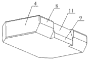
Fig. 4 is the overall structure sketch map of the snap close of the utility model.
Fig. 5 is connected the overall structure sketch map on the mould for the utility model.
Wherein, the parts name that Reference numeral is corresponding is called:
1-control panel, 2-latch, 3-chute, 4-snap close, 5-spring, 6-boss; 7-draw-in groove, 8-deck, 9-card is protruding, 10-inclined-plane, 11-coupling face; 12-wearing plate, 13-through hole, 14-spring eye, 15-the first group ejector retainner plate, 16-the second group ejector retainner plate; 17-the second group top backboard, 18-float plate, 19-solid plate, 20-moving platen, 21-push rod.
The specific embodiment
Below in conjunction with embodiment the utility model is done to specify further, but the embodiment of the utility model is not limited thereto.
Embodiment
Shown in Fig. 1~5, the utility model mainly is made up of control panel 1, on this control panel 1, is provided with chute 3, and said chute 3 is a groove, and runs through the upper and lower bottom surface of control panel 1, and is as shown in Figure 3.On said control panel 1, also be provided with the latch 2 that is complementary with chute 3, said latch 2 one ends are arranged on chute 3 inside, and the width of this latch 2 is less than the width of chute 3, and promptly this latch 2 can slide up and down along the sidewall of chute 3, and is as shown in Figure 1.Simultaneously, the thickness of this latch 2 is more than or equal to the degree of depth of chute 3, and it is consistent with the degree of depth of chute 3 that present embodiment preferentially is set to the thickness of latch 2, thereby makes the left surface flush of the left surface and the control panel 1 of latch 2.For the ease of using screw that latch 2 is connected on the mould, on this latch 2, also be provided with through hole 13, same, on said control panel 1, also be provided with through hole 13.
On said control panel 1, also be provided with elastic parts, said elastic parts comprises snap close 4, and this snap close 4 is made by mould steel.For the ease of connecting snap close 4, on said control panel 1, also be provided with draw-in groove 7, said draw-in groove 7 is made as two, and these two draw-in grooves 7 are separately positioned on the left and right sides of chute 3, and symmetrically.Simultaneously, on said snap close 4, be provided with the deck 8 that is complementary with draw-in groove 7, said deck 8 also is two, and these two decks 8 are corresponding one by one with draw-in groove 7.Be provided with also between these two decks 8 that to be positioned at the inner card of chute 3 protruding 9, as shown in Figure 4.
To block protruding 9 when in chute 3, sliding into protruding 9 places of card for the ease of latch 2 and eject chute 3, and simultaneously deck 8 ejected draw-in groove 7, the thickness of said card protruding 9 then is provided with inclined-plane 10, like Fig. 1, shown in 2 more than or equal to the thickness of deck 8 on said latch 2.Simultaneously on said card protruding 9, then be provided with the coupling face 11 that is complementary with inclined-plane 10, as shown in Figure 4.Protruding 9 for the ease of ejecting card, promptly eject snap close 4, on said snap close 4, also be provided with boss 6 with spring 5.For the ease of connecting boss 6, on said snap close 4, be provided with screwed hole, simultaneously, on said boss 6, be provided with the external screw thread that is complementary with screwed hole, said boss 6 through its external screw thread be connected on the snap close 4 after screwed hole on the snap close 4 cooperates.On this boss 6, also be provided with spring eye 14, as shown in Figure 1, an end of said spring 5 then is arranged in this screwed hole 14.
For the ease of protection snap close 4, prevent that snap close 4 is worn in use, below said snap close 4, also be provided with wearing plate 12.Said wearing plate 12 is a slab construction, and is made by ordinary steel.For the ease of this wearing plate 12 is connected on the mould, on said wearing plate 12, also be provided with and counter sink.
During installation, use screw to pass behind the counter sink on the wearing plate 12 this 12 is fixed on first group of ejector retainner plate 15, and the disappearance of the head of screw of this screw forms stealthy screw in counter sink.After using screw to pass the through hole 13 on the control panel 1 then control panel 1 is connected on first group of ejector retainner plate 15, as shown in Figure 5.4 of said snap closes are between second group of ejector retainner plate 16 and wearing plate 12, and the other end of said spring 5 then is close on second group of ejector retainner plate 16 and the second group of top backboard 17, and makes this spring 5 be in compressive state.After using screw to pass the through hole 13 on the latch 2 at last latch 2 is connected on the float plate 18, thereby the utility model is installed on the mould, and a utility model is installed respectively in the mould left and right sides, as shown in Figure 5.
During work, open cover half during die sinking for the first time and pull 19, then open moving platen 20 during die sinking for the second time, use push rod 21 to eject product then.When ejecting, under the effect of push rod 21, upwards promote first group of ejector retainner plate 15 and second group of ejector retainner plate 16.Because float plate 18 is fixed, then latch 2 is fixed, and control panel 1 cooperates the back to move up along latch 2 through its chute 3 with latch 2.The coupling face 11 that is moved upward to card protruding 9 when control panel 1 contacts rear control plate 1 with the inclined-plane 10 of latch 2 to be continued to move up; Under the effect on the inclined-plane 10 of latch 2, ejected chute 3 and block protruding 9; Thereby spring 5 further is compressed; Deck 8 is ejected draw-in groove 7 simultaneously, and promptly snap close 4 can move relative to controlling 1.Eject the first time of at this moment, promptly having accomplished product.Knock-pin 21 continuation effects; 15 maintenances of first group of ejector retainner plate are motionless; Snap close 4 continues to move up under the effect of knock-pin 21, thereby this snap close 4 is relatively moved with control panel 1, and this snap close 4 is separated with wearing plate 12 simultaneously; Eject the second time up to accomplishing product, thereby product is ejected mould.
As stated, just can realize the utility model preferably.
Claims (8)
1. twice based on mould ejects controlling organization, it is characterized in that: mainly by control panel (1), match with this control panel (1) and can form along the latch (2) that this control panel (1) slides, on said control panel (1), also be provided with elastic parts.
2. based on mould twice according to claim 1 ejects controlling organization; It is characterized in that: on said control panel (1), be provided with the chute (3) that is complementary with latch (2), said latch (2) with can slide up and down along the sidewall of chute (3) after chute (2) cooperates.
3. based on mould twice according to claim 1 and 2 ejects controlling organization, it is characterized in that: said elastic parts comprises the snap close (4) that is arranged on control panel (1) and goes up and match with latch (2), is arranged on the boss (6) that spring (5) were gone up and had to this snap close (4).
4. based on mould twice according to claim 3 ejects controlling organization, it is characterized in that: also be provided with the draw-in groove (7) that lays respectively at chute (3) both sides at said control panel (1); Simultaneously, on said snap close (4), be provided with and draw-in groove (7) two decks (8) one to one, between said two decks (8), also be provided with and be positioned at the card protruding (9) that chute (3) is inner and match with latch (2).
5. based on mould twice according to claim 4 ejects controlling organization, it is characterized in that: on said latch (2), be provided with inclined-plane (10), on said card protruding (9), be provided with the coupling face (11) that matches with this inclined-plane (10) simultaneously.
6. eject controlling organization according to claim 4 or 5 described based on mould twice, it is characterized in that: also be provided with wearing plate (12) in said snap close (4) below.
7. based on mould twice according to claim 6 ejects controlling organization, it is characterized in that: on said control panel (1) and latch (2), be equipped with through hole (13).
8. based on mould twice according to claim 7 ejects controlling organization, and it is characterized in that: said snap close (4) is made by mould steel.
Priority Applications (1)
| Application Number | Priority Date | Filing Date | Title |
|---|---|---|---|
| CN 201220135705 CN202572734U (en) | 2012-03-31 | 2012-03-31 | Twice ejection control mechanism based on mold |
Applications Claiming Priority (1)
| Application Number | Priority Date | Filing Date | Title |
|---|---|---|---|
| CN 201220135705 CN202572734U (en) | 2012-03-31 | 2012-03-31 | Twice ejection control mechanism based on mold |
Publications (1)
| Publication Number | Publication Date |
|---|---|
| CN202572734U true CN202572734U (en) | 2012-12-05 |
Family
ID=47242184
Family Applications (1)
| Application Number | Title | Priority Date | Filing Date |
|---|---|---|---|
| CN 201220135705 Expired - Fee Related CN202572734U (en) | 2012-03-31 | 2012-03-31 | Twice ejection control mechanism based on mold |
Country Status (1)
| Country | Link |
|---|---|
| CN (1) | CN202572734U (en) |
Cited By (3)
| Publication number | Priority date | Publication date | Assignee | Title |
|---|---|---|---|---|
| CN103862600A (en) * | 2014-04-02 | 2014-06-18 | 福尔斯通电子(昆山)有限公司 | Mould with double-ejection mechanism |
| CN104492960A (en) * | 2014-12-03 | 2015-04-08 | 柳州通为机械有限公司 | Mold for mounting bracket on automotive brake pedal |
| CN104708785A (en) * | 2015-04-03 | 2015-06-17 | 韩立艳 | Clutch control mechanism for double-ejection template of mold |
-
2012
- 2012-03-31 CN CN 201220135705 patent/CN202572734U/en not_active Expired - Fee Related
Cited By (3)
| Publication number | Priority date | Publication date | Assignee | Title |
|---|---|---|---|---|
| CN103862600A (en) * | 2014-04-02 | 2014-06-18 | 福尔斯通电子(昆山)有限公司 | Mould with double-ejection mechanism |
| CN104492960A (en) * | 2014-12-03 | 2015-04-08 | 柳州通为机械有限公司 | Mold for mounting bracket on automotive brake pedal |
| CN104708785A (en) * | 2015-04-03 | 2015-06-17 | 韩立艳 | Clutch control mechanism for double-ejection template of mold |
Similar Documents
| Publication | Publication Date | Title |
|---|---|---|
| CN201755897U (en) | Inclined slide type secondary core drawing mechanism of injection mould | |
| CN202572734U (en) | Twice ejection control mechanism based on mold | |
| CN202668909U (en) | Secondary sliding block core pulling mechanism | |
| CN201559289U (en) | Inverted mold | |
| CN202062561U (en) | Sliding block core pulling mechanism capable of realizing auxiliary pressing for product | |
| CN101954723A (en) | Secondary ejecting mechanism of improved type invertedly-buckled bottle cap plastic injection mold | |
| CN202088392U (en) | Die with backflow glue injection structure | |
| CN106863715B (en) | Double-color mold | |
| CN204622507U (en) | Injection mould slanted structure | |
| CN201784103U (en) | Secondary core-pulling mechanism for inclined guide pillar of base mould of automobile headlamp | |
| CN205763749U (en) | Die casting and pull bar assembling structure thereof | |
| CN201120682Y (en) | Plastic rubber mold | |
| CN103660150A (en) | Mold with submarine gate in sliding block | |
| CN201800207U (en) | Improved secondary ejection mechanism of injection mold for inverted bottle covers | |
| CN202388664U (en) | Mold seizing and air trapping prevention device for front mold core of plastic mold | |
| CN201693743U (en) | Double-rail type slide for demoulding fastener products | |
| CN202781728U (en) | Injection mould ejector with continuously-variable ejecting distance | |
| CN207972260U (en) | A kind of Double-color injection mold structure of delay core pulling | |
| CN202862517U (en) | Mould for feeding submerged adhesive opening in slide block | |
| CN202428629U (en) | Automotive decorative piece de-molding mechanism with buckle | |
| CN204471770U (en) | The simplification secondary ejecting mechanism of mould | |
| CN203726751U (en) | Sliding block mechanism used for plastic mold | |
| CN213227315U (en) | Injection mold with end cover secondary ejection mechanism | |
| CN203863927U (en) | Die for producing spray valve large button | |
| CN203818459U (en) | Injection mould with slide block backhoe de-molding structure |
Legal Events
| Date | Code | Title | Description |
|---|---|---|---|
| C14 | Grant of patent or utility model | ||
| GR01 | Patent grant | ||
| C17 | Cessation of patent right | ||
| CF01 | Termination of patent right due to non-payment of annual fee |
Granted publication date: 20121205 Termination date: 20130331 |