A kind of structure improved rotary nozzle
Technical field
The utility model belongs to the operation technique field, relates to a kind of shower nozzle, particularly a kind of structure improved rotary nozzle.
Background technology
Cleaning machine is widely used in washing vehicle, external wall of house face and ground etc.The structure of hole for water spraying and cleaning performance have direct relation in the cleaning machine nozzle core, usually be divided into 0 °, 15 °, 25 °, 40 ° according to the water type that nozzle sprayed, 0 ° of water type that nozzle sprayed is linearly, and water under high pressure acts on a bit, cleaning performance the best.One time cleaning area is little, can't satisfy the needs that large tracts of land is cleaned.40 ° of water types that nozzle sprayed are 40 ° of fan types, and water under high pressure disperses, and cleaning performance is poor, and one time cleaning area is big, are suitable for large tracts of land and clean.
At the problem of above-mentioned existence, the someone has designed rotary nozzle.For example, Chinese patent literature once disclosed a kind of rotary nozzle of washer [China Patent No.: ZL200720191999.8; Granted publication CN201124134Y], a nozzle carrier that connects spray boom, nozzle carrier connects nozzle cage, nozzle cage has the shower nozzle sheath outward, nozzle core is arranged in the nozzle cage, nozzle core is shaped on hole for water spraying, nozzle is installed in the head of nozzle cage is revolved seat, nozzle core revolves the seat activity with nozzle and cooperates, and nozzle core connects the nozzle core retainer plate, and the nozzle core cover connects fixator pins, fixator pins has the pin cap, between fixator pins and the nozzle core retainer plate water spray runner is arranged, between nozzle core retainer plate and the nozzle cage spray chamber is arranged, in nozzle carrier, be shaped on two and be mutually 180.The logical spray chamber in inlet opening in.Shower nozzle in this structure shower nozzle has certain spinfunction, but owing to still exists a lot of deficiencies.Because water enters the eddy current instability that produces in the rotating drum, thereby cause the shower nozzle swing not have rule, make that the cleannes of cleaning are inconsistent.
Summary of the invention
The purpose of this utility model is to have the problems referred to above at existing technology, has proposed a kind of shower nozzle spin stabilization and clocklike structure improved rotary nozzle.
The purpose of this utility model can realize by following technical proposal: a kind of structure improved rotary nozzle, comprise the sprayer body that has the eddy flow chamber in a tubular form, end in the eddy flow chamber is fixed with the nozzle boss with delivery port, the other end in the eddy flow chamber is fixed with the Connection Block with intake tunnel, the outer end of Connection Block passes sprayer body and is connected with water supply connector, has the inlet opening that is communicated with intake tunnel and eddy flow chamber in the inner of Connection Block, it is characterized in that, described Connection Block the inner is arranged with rotating mechanism, in the eddy flow chamber, tilt to be provided with nozzle component, one end of nozzle component and nozzle boss flexibly connect, the other end links to each other with rotating mechanism, can drive the nozzle component rotation when rotating mechanism rotates.
The rotating mechanism of this rotary nozzle is set on the Connection Block, and rotation is the axle rotation with the Connection Block, so have the characteristics stably of rotating.Drive nozzle component around the nozzle boss rotation by rotating stably rotating mechanism, the nozzle component rotation also can be very steady and certain rules is arranged as can be known.
In above-mentioned structure improved rotary nozzle, described Connection Block the inner has annular groove, described rotating mechanism comprises the runner that is set on the annular groove sidewall and the runner cover plate between annular groove and runner, the one side of runner cover plate is resisted against on the annular groove of Connection Block, another side leans on mutually with runner, and above-mentioned core assembly is connected on the runner.
In above-mentioned structure improved rotary nozzle, an end of described runner leans on mutually with the runner cover plate, has some blades leaning on the face mutually of runner, and the other end of runner has eccentric groove.
In above-mentioned structure improved rotary nozzle, described blade quantity is 8~10, and to be that the center is curved with the runner axle center outwards disperse and along the circumferential direction evenly distribute blade.
In above-mentioned structure improved rotary nozzle, described inlet opening quantity is 1~4, and the inlet opening is obliquely installed in the same direction and the delivery port of inlet opening is positioned on the sidewall of annular groove.
In above-mentioned structure improved rotary nozzle, the delivery port of described inlet opening is relative with the sidewall of blade.Water enters on the sidewall that the inlet opening is injected in blade again from intake tunnel, and the injection of water drives runner and rotates.
In above-mentioned structure improved rotary nozzle, described nozzle component comprises that shower nozzle and shower nozzle with apopore change core, one end of shower nozzle and nozzle boss flexibly connect, and the other end links to each other with the end that shower nozzle changes core, and the other end that shower nozzle changes core is connected in the eccentric groove.
In above-mentioned structure improved rotary nozzle, described shower nozzle changes in-core and has runner that communicates with the eddy flow chamber and the honeycomb duct that is communicated with the apopore of runner and shower nozzle.
In above-mentioned structure improved rotary nozzle, be provided with the rolling annulus that adopts elastomeric material to make between described shower nozzle commentaries on classics core and the sprayer body, the rolling circle ring set is located at shower nozzle to be changeed on the core.Because rubber is comparatively soft, so the rolling annulus is more steady in rotation process, noise is lower.
In above-mentioned structure improved rotary nozzle, described sprayer body is provided with overcoat outward.
Compared with prior art, the rotation of the shower nozzle of this structure improved rotary nozzle steadily and have certain rules, thereby effectively avoid repeated washing to same area, make to have that cleaning performance is good, speed fast, the advantage of energy savings.
Description of drawings
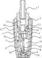
Fig. 1 is the complete section structural representation of this structure improved rotary nozzle.
Fig. 2 is the partial cutaway structural representation of this structure improved rotary nozzle.
Fig. 3 is the runner bucket cross section structure schematic diagram of this structure improved rotary nozzle.
Among the figure, 1, water supply connector; 2, Connection Block; 21, intake tunnel; 22, inlet opening; 23, annular groove; 3, runner cover plate; 4, runner; 41, eccentric groove; 42, blade; 5, sprayer body; 51, eddy flow chamber; 6, shower nozzle changes core; 61, runner; 62, honeycomb duct; 7, rolling annulus; 8, shower nozzle; 81, apopore; 9, nozzle boss; 10, seal; 11, overcoat.
The specific embodiment
Below be specific embodiment of the utility model and in conjunction with the accompanying drawings, the technical solution of the utility model is further described, but the utility model be not limited to these embodiment.
As depicted in figs. 1 and 2, this rotary nozzle comprises that sprayer body 5, nozzle boss 9, Connection Block 2, overcoat 11, shower nozzle 8, shower nozzle change core 6, runner 4, runner cover plate 3.
Specifically, sprayer body 5 in a tubular form and have an eddy flow chamber 51, overcoat 11 parcels are arranged on the outside of sprayer body 5, shower nozzle 8, shower nozzle change core 6, runner 4, runner cover plate 3 and are arranged in the eddy flow chamber 51; Nozzle boss 9 and Connection Block 2 are separately fixed at the two ends in eddy flow chamber 51, in order to improve the sealing between nozzle boss 9 and Connection Block 2 and the sprayer body 5, so be equipped with seal 10 between nozzle boss 9 and Connection Block 2 and sprayer body 5.
Has intake tunnel 21 on the Connection Block 2, the outer end of Connection Block 2 passes sprayer body 5 water supply connector 1 that has been threaded, has annular groove 23 in the inner of Connection Block 2, also have the inlet opening 22 that is communicated with intake tunnel 21 and eddy flow chamber 51 in the inner of Connection Block 2, the delivery port of inlet opening 22 is positioned on the sidewall of annular groove 23.
Runner cover plate 3 and runner 4 are set on the annular groove 23 of Connection Block 2 inner segments successively, and the one side of runner cover plate 3 is resisted against on the recessed shoulder of Connection Block 2, and another side leans on mutually with runner 4.One end of runner 4 leans on mutually with runner cover plate 3, has some blades 42 leaning on the face mutually of runner 4, and the other end of runner 4 has eccentric groove 41.
Have delivery port on the nozzle boss 9, an end of shower nozzle 8 and nozzle boss 9 flexibly connect, and shower nozzle 8 has apopore 81, and the apopore 81 of shower nozzle 8 is relative with the delivery port of nozzle boss 9.Nozzle boss 9 and shower nozzle 8 all adopt ceramic material to make.The other end of shower nozzle 8 links to each other with the end that shower nozzle changes core 6, shower nozzle commentaries on classics core 6 is obliquely installed and the other end is arranged in the eccentric groove 41 of runner 4, when runner 4 rotated, can drive shower nozzle 8 and shower nozzle commentaries on classics core 6 was that the center rotates along sprayer body 5 inwalls with shower nozzle 8 with nozzle boss 9 tie points together.Be arranged with the rolling annulus 7 that adopts elastomeric material to make on shower nozzle commentaries on classics core 6, rolling annulus 7 is resisted against sprayer body 5 inwalls; Shower nozzle changes the honeycomb duct 62 that has runner 61 that communicates with eddy flow chamber 51 and the apopore 81 that is communicated with runner 61 and shower nozzle 8 in the core 6.
As shown in Figure 3, above-mentioned blade 42 quantity are 9, and to be that the center is curved with runner 4 axle center outwards disperse and along the circumferential direction evenly distribute blade 42.Above-mentioned inlet opening 22 quantity are 2, and the delivery port of inlet opening 22 is obliquely installed towards same circumferencial direction, and the delivery port of inlet opening 22 is relative with the sidewall of blade 42.
In sum, the concrete use of this rotary nozzle is: at first, water supply connector 1 is communicated with water inlet pipe, press water enters the intake tunnel 21 in the Connection Block 2, from inlet opening 22, eject again, because the delivery port of inlet opening 22 is relative with the sidewall of blade 42, so the water that ejects is beaten on the sidewall of blade 42 and make blade 42 rotate, runner 4 drive shower nozzles 8 and shower nozzle change core 6 together with shower nozzle 8 and nozzle boss 9 tie points be the center along the rotation of sprayer body 5 inwalls, the apopore 81 of shower nozzle 8 can along with shower nozzle 8 rotary oscillations change towards; Flow into eddy flow chamber 51 groove of water between two blades 42 simultaneously.Then, water changes the runner 61 of core 6 and apopore 81 that honeycomb duct 62 enters shower nozzle 8 and the delivery port ejection of passing nozzle boss 9 from eddy flow chamber 51 by shower nozzle.
Specific embodiment described herein only is that the utility model spirit is illustrated.The utility model person of ordinary skill in the field can make various modifications or replenishes or adopt similar mode to substitute described specific embodiment, but can't depart from spirit of the present utility model or surmount the defined scope of appended claims.
Although this paper has used water supply connector 1 morely; Connection Block 2; Intake tunnel 21; Inlet opening 22; Annular groove 23; Runner cover plate 3; Runner 4; Eccentric groove 41; Blade 42; Sprayer body 5; Eddy flow chamber 51; Shower nozzle changes core 6; Runner 61; Honeycomb duct 62; Rolling annulus 7; Shower nozzle 8; Apopore 81; Nozzle boss 9; Seal 10; Overcoat 11 terms such as grade, but do not get rid of the possibility of using other term.Using these terms only is in order to describe and explain essence of the present utility model more easily; They are construed to any additional restriction all is contrary with the utility model spirit.